Abstract
The synthesis of high-performance adhesives imposes stringent requirements on the design of stirred reactors: simultaneous achievement of efficient mixing and minimal energy dissipation in highly viscous media remains the principal challenge. In this study, computational fluid dynamics (CFD) was employed to solve the Navier–Stokes equations for the high-viscosity epoxy system and numerically simulating the flow fields of four representative reactor configurations across a prescribed range of rotational speeds. Specifically, the four representative reactor configurations were (i) single-serrated shaft, (ii) eccentric single-serrated shaft, (iii) uniaxial single-blade paddle combined with a single-serrated dual-axis assembly, and (iv) biaxial single-blade paddle coupled with a single-serrated triaxial assembly. The mixing performance was quantitatively assessed by systematically comparing the evolution of mixing speed, vorticity fields, restricted power consumption, and mixing time across a range of rotational speeds. The results demonstrated that the synergistic deployment of an eccentric impeller and a differential-speed single-propeller shaft effectively disrupted the axisymmetric flow pattern, compressed the chaotic isolation zones, and intensified both axial exchange and global chaotic mixing. Among the configurations examined, the uniaxial single-propeller–single-serrated biaxial arrangement reduced the mixing time by 13.43% and cut the specific energy consumption by approximately 58.32%, thereby attaining markedly higher energy efficiency. This research will provide guidance for the study of efficient mixing of adhesives.
1. Introduction
Modern industry with the rapid development of adhesives, as an important functional material, has had its application areas continue to broaden [1]. In recent years, adhesives have been extensively used in the construction [2], automotive [3], aerospace [4], electronics [5], and biomedical industries [6], and the market demand for their performance is increasing. In the face of a wide variety of application environments, the types of fillers and additives employed have also become increasingly diverse, which makes the uniformity of adhesive products during the synthesis process a challenging issue [7,8,9,10]. At present, only a few articles have attempted to prove that the uniformity of various fillers during the adhesive synthesis process can affect the quality and performance of the product, rather than studying how to improve its uniformity.
The stirring reactor is the key piece of equipment in the process of adhesive synthesis, and the rationality of its spatial and temporal structure directly determines the mixing and dispersing effect of adhesive raw materials and fillers, as well as the reaction efficiency in the reactor [11,12,13]. In order to enhance the mixing and reaction efficiency of high-viscosity materials, the theory of stirring-enhanced mixing came into being. On this basis, scientists have carried out a lot of fruitful research, for example, by changing the shape of the stirring impeller [14], the stirring rate, the geometry of the reactor [15,16], and the spatial and temporal combinations between the impellers [17,18], etc., to further strengthen the mixing and reaction process. Among them, the serrated dispersion disc has attracted attention due to its superior radial local shear capacity and turbulence intensity compared to other common impellers (such as Rushton impellers, anchor impellers, etc.) of the same size. Moreover, it demonstrates excellent mixing performance when dealing with high-concentration solid suspensions and insoluble substances. However, it also has issues such as a relatively monotonous flow direction in the generated flow field and easy deposition at the bottom [19]. For the problem of stirring and mixing in high-viscosity systems, the introduction of axial impellers has become an important direction.
Currently, computational fluid dynamics (CFD) has been recognized as a tool that can comprehensively and efficiently analyze the variation in the flow field in stirred tanks [20,21,22,23,24,25,26,27]. The literature shows that CFD simulation can efficiently reveal the rheological conditions in the reactor, which is useful for the optimization of the stirrer structure and operating parameters through the comparison of traditional experiments and simulations [14,15,16,17,22,23,24]. For example, Wang et al. [17] used Fluent software to simulate and install multiple impellers and eccentric multi-shafts in a vertical stirred kettle, which changed the material in the reactor from local chaotic mixing to overall chaotic mixing; Shuai et al. [16] used CFD to add blending rods in a horizontal kneader, which improved the efficiency of the material exchange in different mixing spaces. In this study, a combination of different impeller differential speeds is proposed to improve the mixing degree of a high-viscosity material system.
Based on the existing research on the optimization of the stirred reactor for high-viscosity materials, this work is mainly performed with the help of the laminar flow model in the Fluent software of computational fluid dynamics (CFD). In the high-viscosity epoxy resin fluid system, this work focuses on the impact of the serrated disc impeller on the material flow mixing in the reactor and compares the mixing speed and power consumption under different stirring speeds. In addition, this work also investigates the mixing performance and the change in the flow field in the kettle after the introduction of the eccentric impeller and the differential axial single paddle shaft of the stirring device in the highly viscous system. Finally, the mixing capability of each stirring device in the mixing process of high-viscosity materials was evaluated by the power consumption per unit volume of unusual stirring devices and the mixing time at different impeller rotation speeds. This study can provide an idea and basic data for the optimized design of a high-viscosity fluid and adhesive synthesis reactor.
2. Models and Methods
2.1. Geometric Models and Meshes
We established a geometric model of the stirring device based on the actual parameters of the production stirring device for the adhesive. The structure of the stirring device is shown in Figure 1. In the numerical simulation, the stirred kettle has a diameter of 356 mm and a height of 502 mm, and the upper and lower walls of the kettle are 30 mm apart in order to minimize the effect of the flow dead zone in the upper and lower bottom corners. The mixing kettle impellers are an axial-flow single-blade paddle impeller and a serrated disc impeller; the exact dimensions are shown in Figure 1 and Table 1. Through the unique spatial combinations of the above two types of impellers, a single-serrated-shaft mixing kettle (SSDM), an eccentric single-serrated-shaft mixing kettle (ESSDM), a uniaxial single-blade paddle single-serrated biaxial mixing kettle (ESDM-SAS), and a biaxially oriented single-blade paddle single-serrated triaxial mixing kettle (ESDM-DSAS) are formed. In this study, the performance of these four stirring devices in the stirring flow field of a high-viscosity material (epoxy resin) is analyzed. In the stirred kettle-4, the paddles of the two axial single-blade paddle shafts are arranged in a staggered manner. In terms of the meshing section, due to the complex geometry of the impeller, we used an unstructured grid for construction. This unstructured grid was created using the mesh generation software of Ansys 2022R1. To improve the calculation accuracy, we increased the grid density around the impeller, with the minimum grid size being 3 mm, as shown in Figure 2.
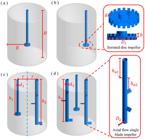
Figure 1.
The geometric configuration of the agitation reactor and its impeller scaling diagram. (a) SSDM. (b) ESSDM. (c) ESDM-SAS. (d) ESDM-DSAS.

Table 1.
Geometric dimensions of tank.
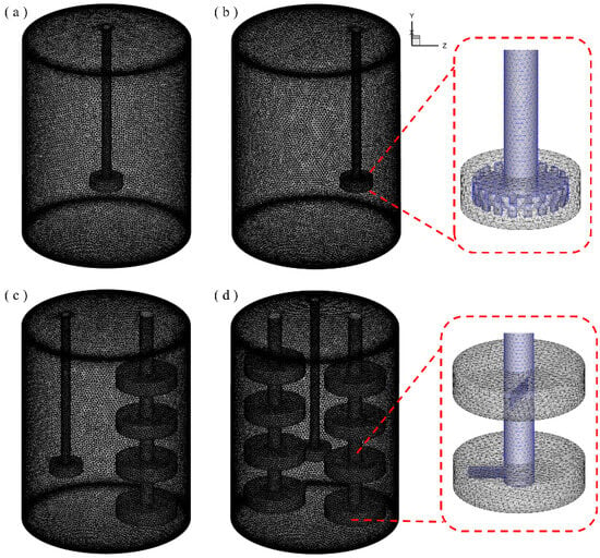
Figure 2.
The division of the calculation area and the thumbnail of its grid construction. (a) SSDM. (b) ESSDM. (c) ESDM-SAS. (d) ESDM-DSAS.
2.2. Governing Equation
The flow process of fluid material inside the agitator follows the laws of conservation of mass, momentum, and energy, and its basic set of control equations is shown below [24]:
- Mass equation:
2.3. Materials and Measurement Strategies
2.3.1. Materials
Epoxy resin was selected as the simulation medium material, and its related material parameters are shown in Table 2.

Table 2.
Fluid parameters.
In this study, the value of the stirring Reynolds number can be obtained using the following equation [14,15]:
is the impeller diameter in m, is the impeller rotational speed, is the material density, and is the dynamic viscosity.
2.3.2. Power Consumption
In this study, we use the power consumption per unit volume, , to evaluate the performance of the stirrer. After the simulation system reaches a steady state, we first obtain the moment value . Then, the power consumption is calculated using the following equation [14,15,17]:
where , , and are the power consumption of each impeller; V is the volume inside the mixing kettle in m3; , , and are the torque values of their respective impellers in ; and is the rotational speed of their corresponding impellers in r/min.
2.4. Mixing Time (tm)
Mixing time is an important metric in the production of the adhesive industry as it reflects the time required to complete the mixing process [15]. Figure 3 illustrates the feed point () and six monitoring points ( − ) of the liquid tracer. By following the dispersion of the tracer through numerical simulations, we can estimate the mixing time. The determination of the mixing time follows the 95% principle [28,29]; i.e., the mixing process is considered to be complete when the tracer reaches a 95% homogeneous distribution in the kettle.
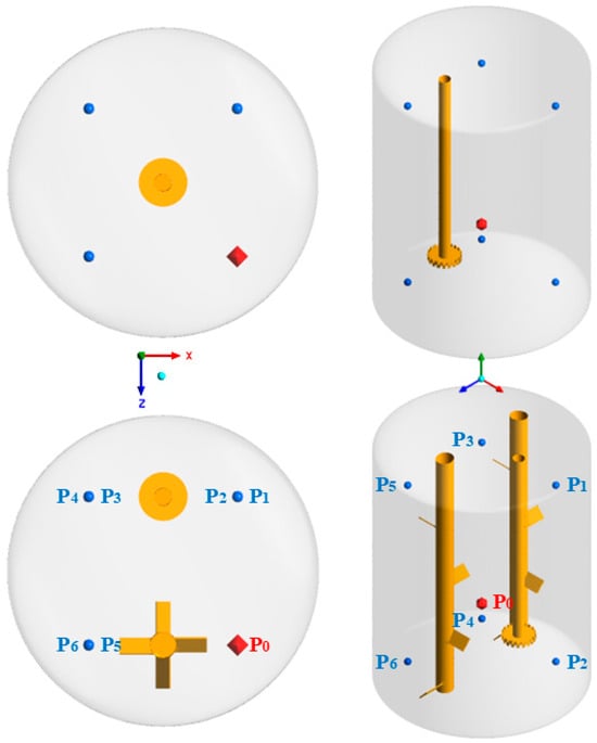
Figure 3.
Injection and observation points for liquid tracers in stirred reactors (used for calculating the mixing tm).
2.5. Simulation Boundary Condition Section
In order to deeply study the flow behavior of high-viscosity adhesives in the reactor under different stirring modes, we determined the flow state by calculating the stirring Reynolds number (as shown in Equation (6)). Through calculation, we obtained Reynolds numbers of the four stirring devices ranging from 47.04 to 294. Furthermore, we chose to use a laminar flow model to simulate and describe the flow changes. The mathematical model is described as shown in Equations (1)–(5). In the simulation process, this study adopts the multi-reference system (MRF) method, which defines the region where the blade is located as the rotating dynamic domain and the other regions as the static domain, and the two are divided as shown in Figure 2. In this study, we mainly use Ansys Fluent 2022 R1 software to carry out steady state solution calculations, and the simulation system is single-phase, aiming to provide support for the structural optimization of the stirred reactor in the mixing process of epoxy resin adhesive. The pressure–velocity coupling was solved using the SIMPLE algorithm, and the stirring direction was counterclockwise. The convergence residual was set to 10−5. The pressure term of the control equation with the under-relaxation factor is set to 0.3, the density term is set to 1, the body forces term is set to 1, and the momentum term is set to 0.7. The wall of the stirring tank is set as a stationary wall, and the stirring shaft and its impeller are set as a moving wall.
We integrated the simulation and speed settings (100–600 r/min) of the multi-axis differential stirring device by Qin et al. [30], as well as the speed settings of the double-axis stirring by Wang et al. [17]. We found that at 300 r/min, the flow field conditions could be most representative in terms of the relevant situations. Furthermore, by considering the typical rotational speeds of the Rushton impeller [31] and the toothed impeller [19], we set the rotational speed ratio between the differential shaft (a stirring shaft that rotates at a speed different from that of the main shaft; in this study, it is referred to as an axial single-blade shaft) and the toothed main shaft at 1:3. Therefore, in this study, we mainly set the main shaft of the gear to 300 r/min and the differential shaft to 100 r/min.
2.6. Grid Independence Verification
In the numerical simulation, the coordinate origin was set at the uppermost part of the centerline of the mixing shaft with the upward direction being positive. During the calculation process, the meshing quantities of different stirring reactors are as follows: 906,949, 1,872,027, and 3,657,738 for the SSDM reactor; 908,350, 1,875,009, and 3,665,203 for the ESSDM reactor; 1,157,507, 2,539,921, and 5,591,370 for the ESDM-SAS reactor; and the grid numbers of the ESDM-DSAS reactor are 1,399,496, 3,200,711, and 7,504,833. By studying the effect of different number of grids on the total fluid velocity distribution on a line segment parallel to the y-axis with coordinates z = 0 mm and x = −85 mm, the grid model suitable for the next stage of simulation is selected. As shown in Figure 4, the effect of the number of meshes on the velocity distribution in the simulated system is almost negligible. Therefore, in order to save computational resources, 906,949 meshes were selected for the serrated shaft stirred reactor, 908,350 meshes were selected for the eccentric single serrated shaft stirred reactor, 1,157,507 meshes were selected for the uniaxially oriented single-bladed paddle single serrated dual shaft stirred reactor, and 1,399,496 meshes were selected for the biaxially oriented single-bladed paddle single serrated triaxial stirred reactor.
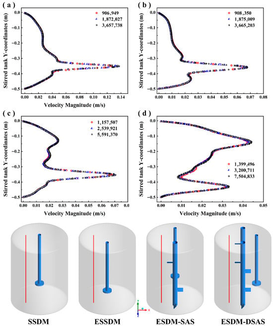
Figure 4.
Effect of the number of meshes on the velocity distribution on axial line segments. (a) SSDM. (b) ESSDM. (c) ESDM-SAS. (d) ESDM-DSAS.
2.7. Model Validation
In this work, the model validation is verified by comparing with the stirrer with almost the same simulation size used in reference (Liangchao L, Ning C et al., 2019 [32]). Liangchao L, Ning C et al. measured the velocity distribution of a highly viscous liquid under laminar flow using the CFD method. We first simulated the flow field inside this stirred kettle and then compared the velocity distribution obtained from the simulation with the simulation data obtained in Liangchao L, Ning C et al. (2019). As shown in Figure 5, the velocity distributions in the simulation with radial positions of r/R = 1.1 and r/R = 1.5 (the ratio of the sampling position to the radius of the impeller) are more consistent with the results in the literature (Liangchao L, Ning C et al., 2019). At the same time, we compare the power quasi-counts at different Reynolds numbers in the literature and find that the differences are low. It should be noted that the geometry of the mixing kettle used for model validation is different from that of the mixing kettle studied in the subsequent chapters, but the mathematical models and simulation methods (e.g., laminar flow model, SIMPLE algorithm, etc.) used in the model validation are exactly the same as those used in the study of the target mixing kettle. Therefore, through the above model validation, it can be inferred that the simulation results in the subsequent chapters are also reliable and accurate.

Figure 5.
Comparison of the simulation model with experimental data in the literature [32]. (a,b) Dimensionless velocity distribution at different positions. (c) Variation in power parity at different Reynolds numbers.
3. Results and Discussion
3.1. Flow Field
Under the condition of a sawtooth disc shaft speed of 300 r·min−1 and an axial single-impeller shaft speed of 100 r·min−1, the velocity distributions of the four stirred reactors and the flow trajectories inside the reactors are shown in Figure 6a,b. In order to analyze the flow field conditions of each reactor more clearly and demonstrate the optimization effect, based on the separation of the lower saddle vortex and the upper vortex in SSDM, we divided the stirring vessel into two areas: the lower area (A) and the upper area (B). As shown in Figure 6(a1), the single serrated disc turbine mixing device produced a symmetric mixing cycle for the high-viscosity fluid, and the symmetric saddle vortices typical of high-viscosity laminar flow fields appeared in the B zone [15,20], which indicated that most of the region was in a mixing isolation, while symmetric annular vortices also appeared in the A zone, which similarly impeded the overall mixing effect of the mixing kettle. The cross-section of YZ velocity distribution of the eccentric serrated disc turbine mixing device is shown in Figure 6(a2). It can be seen that changing the position of the mixing shaft and impeller from the center to eccentric breaks its symmetric flow field structure, almost eliminating the annular vortex in zone A and greatly compressing the isolation zone in zone B near the impeller end, but at the same time, it also leads to a larger range of isolation zones at the far-center end that are more difficult to mix. In order to solve this isolation zone problem, we introduced a low-speed axial single-propeller shaft at the distal end of the eccentric shaft, as shown in Figure 6(a3), and a lot of disordered flows appeared in the flow field after the addition of the axial single-propeller shaft, which caused the isolation zone areas in the A and B zones to be greatly reduced. This phenomenon is consistent with the research results of Wang et al. [17] on the dual-axis mixing device. The emergence of the dual axes has transformed the originally wide isolation area into small vortices, which increased the overall degree of chaotic mixing in the flow field. And after the introduction of two axial single-propeller shafts, as shown in Figure 6(a4), the degree of disorder in the flow field is higher and there are more small eddies, so it can be initially judged that the mixing of materials in this flow field is better.
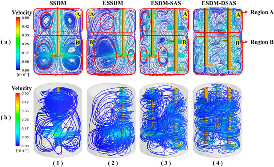
Figure 6.
Velocity distribution of different stirring tanks at 300 r/min. (a) Velocity vector. (b) Three-dimensional streamline diagram.
Figure 6b illustrates the three-dimensional trajectory distribution of material flow in different mixing devices. Figure 6(b1) shows the overall fluid trajectory of the sawtooth disc mixing device under highly viscous material conditions, which can be seen to be mainly composed of regional stratification in the segregation zone and ordered symmetric axial trajectories. Due to the climbing accumulation of highly viscous material under shaft and impeller rotation, the annular vortex in zone A in Figure 6(a1) was formed at its upper end. After changing the impeller position (Figure 6(b2)), its symmetric trajectory is skewed, and part of the material is extruded to a region by the combined effect of gravity and the mixing paddle rotational force, resulting in some axial flow trajectories. However, this also reveals a large range of segregation zones and insufficient flow at the non-eccentric end.
Figure 6(b3) shows the three-dimensional fluid trajectory distributions after the introduction of the axial mono-blade axis. Compared with Figure 6(b1,b2), the introduction of the axial single-blade axis significantly improves the anisotropic flow of the fluid in the stirred kettle. The fluid not only relies on the interaction between the serrated disc impeller and the kettle wall for axial mixing but also achieves mixing in the upper and lower regions with the rotation of the axial single-blade axis, which effectively reduces the mixing isolation zone and the problem of insufficient flow at the non-eccentric end.
Figure 6(b4) demonstrates the internal fluid 3D trajectory distribution of the double single-blade axial sawtooth disc triaxial mixing and stirring device. Compared with Figure 6(b3), the mixing flow is more intensive in its upper and lower regions. The axial flow lines, which originally appeared around the sawtooth disc impeller, changed their trajectories due to the rotation of the two-axial single-blade axes. The fluid flow trajectory has a higher coverage in the mixing kettle, which indicates that the mixing performance of this mixing device is better without considering the power consumption. In conclusion, the addition of axial single-blade paddle axes can effectively enhance the axial flow of highly viscous fluid, which in turn significantly improves the mixing effect in the upper and lower regions and effectively solves the mixing segregation problem existing in a single sawtooth disc shaft. At the same time, under the synergistic effect of the axial single-blade paddle shaft and serrated disc impeller, the disorder of fluid flow is enhanced, which further promotes the chaotic movement of highly viscous fluid in the mixing kettle and thus improves the mixing effect.
3.2. Velocity Distribution
In order to investigate the spatial position and structure of different stirring impellers on the flow field distribution and mixing degree in the stirring tank, this study divides the four stirring kettles into two groups, and the specific grouping and analyzing methods are shown in Figure 7. The first group is a single-axis group, covering single serrated dispersing mixing kettle and eccentric serrated dispersing mixing kettle, for which the speeds in the three axial directions at the distances of r0/r = 1.5, 3.0 and 6.0 from the impeller are selected for analysis (r0 represents the distance from the center of the stirring shaft to the position where this value is located); the second group is a multi-axis group, including two kinds of mixing kettles, namely, ESDM-SAS and ESDM-DSAS, for which the mixing kettle positions are selected as r1/R = 0, 0.45 and 0.9 (r1 represents the distance from the center of the mixing tank to the location of the measured value). For this group, the velocities in the three axial directions were analyzed at the stirring kettle positions of r1/R = 0, 0.45, and 0.9.
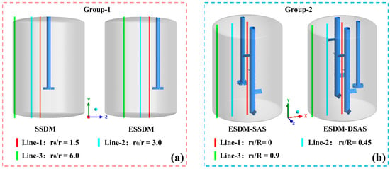
Figure 7.
Velocity distribution grouping and location of values. (a) Single-axis group. (b) Multi-axis group.
As shown in Figure 8, Group 1 demonstrates the velocity distributions of the flow field at different spatial locations in SSDM (single serrated dispersive stirred kettle) and ESSDM (eccentric serrated dispersive stirred kettle). At line1 and line2 positions, the differences in axial, radial, and tangential velocity distributions in the two stirred kettles are small, while at line3 position, which is far away from the impeller, the difference in axial velocities is larger, and the remaining two velocity distributions are smaller. Specifically, the SSDM has an axial velocity distribution close to 0 at the line3 position, whereas the ESSDM has fluctuations in velocity distribution at this position. This difference may be attributed to the fact that line3 is close to the kettle wall in SSDM, and most of the kinetic energy generated by the impeller is absorbed by the material and kettle wall as it propagates to line3, whereas in ESSDM, line3 is located at the center of the non-eccentric end, and even though it is at the same distance from the impeller as that of the SSDM, due to the lack of kettle wall constraints and the fetch position being at the non-eccentric end of the shaft, the flow field in the ESSDM forms a larger vortex-like structure at the non-eccentric end, which is one of the reasons for its larger fluctuation. The difference in the axial velocity distribution changes between the SSDM and the non-eccentric ESSDM at the same distance from the impeller is relatively small, which, combined with the velocity vector distribution plots as described above, indicates that the dispersion effect of the eccentrically placed impellers for the high-viscosity flow field is better than that of the centrally placed impellers. In addition, in the velocity distributions in all directions, the axial and tangential velocities of both structures show peaks, while the radial velocity changes are relatively smooth, which indicates that the serrated dispersing disc has a better effect on the axial and tangential effects on the highly viscous flow field. This is quite similar to the conclusion reached by Torotwa et al. [19] through a horizontal comparison of the toothed dispersion disc and the conventional Rushton impeller.
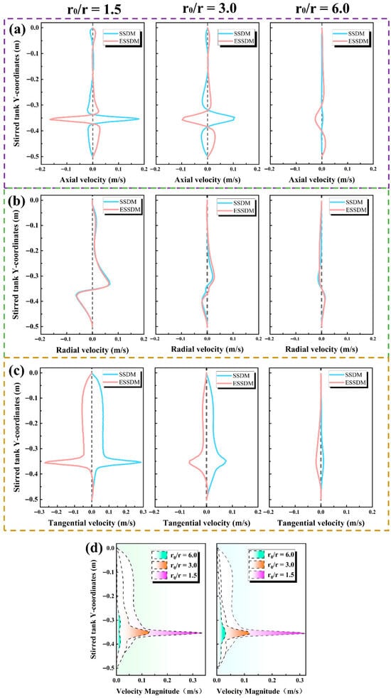
Figure 8.
Distribution of different velocities for Group 1 at different positions in the mixing kettle. (a) Axial velocity. (b) Radial velocity. (c) Tangential velocity. (d) Total velocity.
As shown in Figure 9, Group 2 demonstrates the velocity distribution of the flow field in ESDM-SAS and ESDM-DSAS at different spatial locations. Compared with the single-axis stirring device, the introduction of the differential shaft has a significant effect on the velocity distribution at the upper end of the flow field, and there are multiple peaks in the velocity distribution at the same location, which indicates that the introduction of the differential shaft has a certain modulation effect on the velocity distribution of the overall flow field. Comparing ESDM-SAS and ESDM-DSAS, it can be found that the velocity distribution of the flow field at the non-eccentric end of ESDM-DSAS is smoother than that of ESDM-SAS in all directions. This may be due to the fact that in an asymmetric model such as ESDM-DSAS, the two differential axes almost block the fluctuations generated by the high-speed jagged dispersion disc.
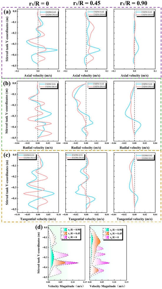
Figure 9.
Distribution of different velocities for Group 2 at different positions in the mixing kettle. (a) Axial velocity. (b) Radial velocity. (c) Tangential velocity. (d) Total velocity.
Overall, the velocity distribution fluctuations at the locations shown in the graph are more significant in the flow field in ESDM-SAS than in ESDM-DSAS, but a more comprehensive comparison needs to be made by subsequent analyses of iso-surfaces, vorticity, and so on, since the fetch locations of the flow field in ESDM-DSAS are located at the non-eccentric end.
3.3. Velocity Iso-Surface Distribution
In order to further investigate the characteristics of the three-dimensional spatial velocity distribution inside the mixing kettle, we show different velocity equivalent surfaces of the four mixing devices (with velocities of 0.01 m/s, 0.05 m/s, 0.1 m/s, and 0.2 m/s). As shown in Figure 10, when the velocity equivalent surface is equal to 0.01 m/s, there is still a large blank area at the upper end of the single serrated disc impeller mixing device, which indicates that whether placed eccentrically or in the center, the single serrated disc impeller can never fully take into account the mixing of the upper and lower half of the zone.
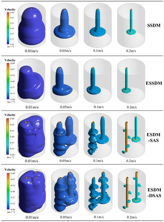
Figure 10.
Cloud view of the distribution of velocity iso-surfaces within the four mixing devices.
For device 3 and device 4, which incorporated an axial single-paddle shaft, most of the upper and lower halves of the mixing kettle were wrapped by the iso-surfaces (the three-dimensional distribution of materials with the same velocity in the mixing tank) at a velocity iso-surface of 0.01 m/s, showing better mixing coverage. When the velocity iso-surface was raised to 0.05 m/s, the equivalence surfaces of all the mixing devices were contracted towards the mixing shaft and the mixing impeller, but part of the region between the high-speed serrated disc shaft and the low-speed axial single-blade shaft in device 3 and device 4 was still in the equivalence surfaces, indicating that this part of the region had a higher fluid velocity and better mixing effect. Further, at velocity iso-surfaces of 0.1 m/s and 0.2 m/s, the velocity iso-surface distributions of all mixing devices were mainly concentrated in the impeller/blade region. At these higher velocity iso-surfaces, the stirring impellers of the multiaxial system hardly interact with each other. This phenomenon may be attributed to the high viscosity of the material in the mixing kettle, which results in a serious obstruction of the kinetic energy transfer of the impeller rotation and makes it difficult to form an effective high-flow-rate mixing in the region away from the impeller. Therefore, in order to enhance the mixing effect of highly viscous materials in the mixing device and to transform the local area mixing into global mixing, the introduction of an axial single-propeller shaft with differential speed is necessary. This design can effectively improve the mixing efficiency of highly viscous fluids, especially in the region away from the impeller.
3.4. Distribution of Vortex Values
In addition to analyzing the velocity distribution of the flow field inside the high-viscosity stirred kettle, this study also investigates the vorticity distribution inside it. As shown in Figure 11, the iso-surface distributions of four stirring devices with different vorticity values at the same stirring speeds (300 r/min and 100 r/min) are demonstrated in this study. Since the iso-surfaces are mainly concentrated around the impeller at high vorticity values, the images were enlarged to show only the region around the impeller.
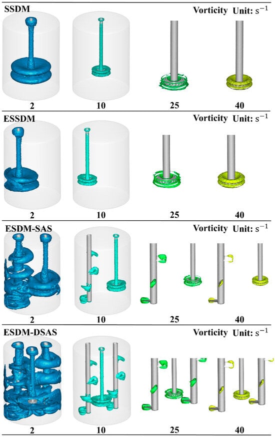
Figure 11.
Cloud view of the distribution of different vorticity iso-surfaces within the four mixing devices.
It can be observed from the figure that under low vorticity conditions (Vorticity = 2 s−1), the eccentric placement of the main impeller did trigger a change in the vortex structure, but this change was relatively small. However, after the introduction of the differential axial single-propeller shaft, the flow field inside the mixing kettle showed significant changes, and the vortex structure around the main impeller was also subjected to a joint change due to the influence of the differential shaft. However, with the increasing value of vorticity, the effect of the introduction of the eccentrically placed main shaft and the differential shaft on the vortex structure around the main shaft gradually diminishes. When the vorticity reaches 40 s−1, the vorticity iso-surfaces around the serrated disc impeller are basically unchanged. This may be due to the blockage of kinetic energy transfer due to the high viscosity of the material and the failure to form a joint influence due to the long distance between the stirring shafts in the same unit. This phenomenon is similar to the conclusion drawn from the velocity iso-surface analysis described above.
3.5. Mixing Time
Figure 12 presents the dimensionless concentration of the liquid tracer in the four stirring devices as a function of time at 300 r/min and 100 r/min. In each stirring device, the dimensionless concentration profile gradually stabilized to a fixed value over time. The results of the study showed that the mixing times of high-viscosity materials in these four mixing devices were 141.87 s, 135.32 s, 122.81 s, and 117.04 s, in that order. It can be found that the eccentric placement of the impeller reduced the mixing time by 4.62% under the same conditions, whereas the introduction of a differential axial single paddle shaft (device 3 and device 4) reduced the mixing time by 13.43% and 17.5%. The specific value of the mixing time can be found in Table 3. Although the same mixed-time limit problem mentioned by Wang et al. [17] also occurred in the double-axis configuration ESDM-SAS, these results indicate that both the eccentric placement of the impeller and the introduction of the differential axial single-propeller shaft positively affected the mixing of the materials in the mixing kettle. And the introduction of the differential axial single-propeller shaft showed a stronger mixing capability for high-viscosity materials due to its greater reduction in mixing time.
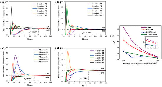
Figure 12.
Normalized concentration of liquid tracer and its mixing time for four mixing devices. (a) SSDM. (b) ESSDM. (c) ESDM-SAS. (d) ESDM- DSAS. (e) Variation of mixing time with rotational speed.

Table 3.
Mixing time of each mixing device.
3.6. Mixing Performance
As shown in Figure 13a and Table 4, the power consumption per unit volume of the four mixing devices under different sawtooth axis rotational speeds presents obvious differences. It can be seen that due to the introduction of the differential axial flow axis, the power consumption per unit volume of the ESDM-SAS and ESDM-DSAS devices is much higher than that of SSDM and ESSDM at the same sawtooth axis rotational speed. In the process of power consumption measurement, we found that the power consumption of the differential axial flow axis is larger than that of its corresponding rotational speed of the sawtooth disc axis. This suggests that the introduction of the differential axial flow shaft, despite enhancing the overall mixing effect of high-viscosity materials in the stirred reactor to a certain extent, also significantly increases the energy consumption per unit volume.
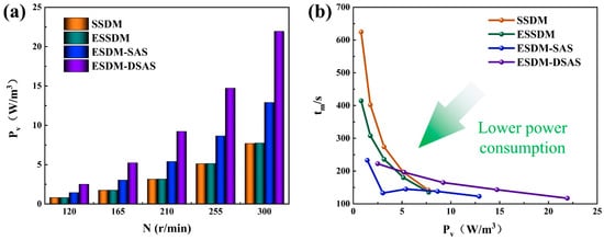
Figure 13.
Power consumption per unit volume and its corresponding mixing time for different mixing speeds in four mixing systems. (a) Power consumption per unit volume. (b) Variation of mixing time with power consumption.

Table 4.
Power per unit volume of each mixing device (W/m3).
In order to minimize the power consumption per unit volume while ensuring the mixing effect, we plotted a line graph between mixing time and power consumption per unit volume in Figure 13b. In the graph, the smaller the Y coordinate, the shorter the mixing time; the smaller the X coordinate, the smaller the power consumption. Therefore, when the image is closer to the origin, it means that the mixing device is able to achieve a shorter mixing time with lower power consumption; i.e., better mixing results are obtained. From the figure, it can be seen that the ESDM-SAS also has a shorter mixing time at a smaller mixing power per unit volume compared to the other three stirring devices. Compared with the dual differential speed shaft, its unit power consumption has decreased by approximately 58.32%. This confirms that with the introduction of a differential axial single paddle shaft, a single shaft is sufficient to intensify the mixing of highly viscous fluid materials. In contrast, the reinforcing effect of the double differential axial single-propeller shaft is not significant, and its power consumption is much higher, which does not meet the requirement of “reducing power consumption while ensuring a shorter mixing time”. Therefore, when dealing with the mixing of high-viscosity materials, the introduction of a differential axial single-propeller shaft for mixing enhancement is a good choice. In addition, the mixing device with one axial single-propeller shaft is better than the mixing device with multiple axial single-propeller shafts in terms of mixing efficiency and mixing performance.
4. Conclusions
This work focuses on the optimized design of a high-viscosity adhesive stirring reactor and analyzes the influence of four stirring devices on the mixing performance of high-viscosity materials with the help of computational fluid dynamics (CFD) technology. Through the detailed study of the mixing enhancement mechanism of SSDM, ESSDM, ESDM-SAS, and ESDM-DSAS, we comprehensively analyze the internal flow field characteristics, which cover the key indexes of the velocity distribution, the flow trajectory, and the mixing time. The results show that the introduction of an eccentric impeller and differential axial single paddle shaft can significantly break the symmetric flow field, reduce the chaotic isolation zone, enhance the axial flow and overall chaotic mixing of materials, and thus effectively shorten the mixing time. However, although the differential axial single-propeller axis enhances the mixing effect, it also significantly increases the power consumption per unit volume. Considering the mixing time and power consumption, the introduction of a single differential axial single-propeller shaft mixing device ensures the mixing efficiency and at the same time has more energy-saving advantages. This study provides useful ideas and basic data for the optimization of the design of the reactor for the synthesis of high-viscosity fluids and adhesives, which can help to improve industrial production efficiency and product quality. Based on the model establishment and simulation results of this study, we suggest that in practical applications, the Reynolds number of the stirring in the mixing tank should be within the range of 47.04–294. Within this range, the results of this article can be more appropriately applied.
This study also has some limitations. For instance, the size of the mixing tank and the selection of the axial single-blade shaft were based on the 50L equipment used in the actual production of the adhesive. If we adopt a more lightweight differential shaft combination, as did the research by Qin et al. [30], it might alleviate the issue of energy consumption. Moreover, this study lacks sufficient research on how the differential stirring device affects the synthesis mechanism of high-viscosity adhesives. In future research, we will employ the theory of chaotic hybridization to overcome this limitation.
Author Contributions
Conceptualization, B.H., F.Q. and R.L.; methodology, B.H., X.T., F.Q. and R.L.; software, L.F. and F.Q.; validation, L.F. and X.T.; formal analysis, L.F.; investigation, L.F. and R.L.; resources, B.H. and X.T.; data curation, B.H., L.F. and X.T.; writing—original draft preparation, B.H. and L.F.; writing—review and editing, B.H., X.T., F.Q. and R.L.; visualization, F.Q.; supervision, F.Q. and R.L.; project administration, B.H., X.T., F.Q. and R.L.; funding acquisition, B.H., X.T. and R.L. All authors have read and agreed to the published version of the manuscript.
Funding
This research was funded by projects for technological innovation and application development in Chongqing (CSTB2023TIAD-KPX0018) and Shanghai Hansi Industrial Co. grant number H20250293. And The APC was funded by Shanghai Hansi Industrial Co. grant number H20250293.
Data Availability Statement
Data will be made available on request.
Conflicts of Interest
The authors declare that they have no known competing financial interests or personal relationships that could have appeared to influence the work reported in this study. The authors declare that this study received funding from Shanghai Hansi Industrial Co. The funder was not involved in the study design, collection, analysis, interpretation of data, the writing of this article, or the decision to submit it for publication.
Nomenclature
| SSDM | Single-serrated-shaft mixing kettle |
| ESSDM | Eccentric single-serrated-shaft mixing kettle |
| ESDM-SAS | Uniaxial single-blade paddle single-serrated biaxial mixing kettle |
| ESDM-DSAS | Biaxially oriented single-blade paddle single-serrated triaxial mixing kettle |
| H | Stirred tank height, mm |
| R | Stirred tank radius, mm |
| r | Shaft setting radius, mm |
| d1 | Serrated disc type blade shaft diameter, mm |
| d2 | Single blade shaft diameter, mm |
| h1 | Serrated disc type blade shaft height, mm |
| h2 | Single blade impeller shaft 2 height, mm |
| h3 | Single blade impeller shaft 3 height, mm |
| D1 | Serrated disc impeller diameter, mm |
| b | Sawtooth height, mm |
| δ | Sawtooth thickness, mm |
| D2 | Single blade length, mm |
| ha1 | Height of the top single blade impeller from the top, mm |
| ha2 | Distance between single blade blades, mm |
| ρ | Density, kg/m3 |
| P | Hydrostatic pressure, pa |
| μ | Dynamic viscosity, kg/(m·s) |
| T | Temperature, K |
| t | Time, s |
| λ | Thermal conductivity W/(m·K) |
| c | Specific heat capacity, J/(kg·K) |
| Re | Reynold number, dimensionless |
| N | Impeller rotational speed, r/min |
| D | Impeller diameter, m |
| Pi | Power of each impeller, W |
| Pv | Power per unit volume, W/m3 |
| V | Volume inside the mixing kettle, m3 |
| Mi | Torque values of their respective impellers, N·m |
| tm | Mixing time, s |
| Np | Dimensionless power number, dimensionless |
| r0 | Distance from the center of the stirring shaft to the position of the value, mm |
| r1 | Distance from the center of the mixing tank to the position of the value, mm |
References
- Ebnesajjad, S.; Landrock, A.H. Front-matter. In Adhesives Technology Handbook; Elsevier: Amsterdam, The Netherlands, 2015; pp. i–iii. [Google Scholar]
- Wu, H.; Wen, T.; Ding, Q.; Zhang, J.; Du, G.; Charrier, B.; Essawy, H.; Pizzi, A.; Yuan, Z.; Zhou, X.; et al. A sustainable adhesive via one-pot simple preparation derived from bio-sourced phytic acid and corn starch for green wood panels: Ideal bonding performance and ultra-high flame retardancy. Chem. Eng. J. 2025, 508, 161026. [Google Scholar] [CrossRef]
- Papadakis, L.; Schiel, M.; Vassilou, V.; Loizou, A.; Dilger, K. Adhesive Bonding of Attachments on Alternate Car Shell Surfaces in Automotive Final Assembly Lines. Procedia CIRP 2014, 18, 180–185. [Google Scholar] [CrossRef][Green Version]
- Poddar, A.K.; Patel, S.S.; Kumar, A.; Patel, H.D.; Satyanarayana, B. Characterization of electrolytically developed copper filled epoxy adhesive for space applications. Hybrid Adv. 2025, 8, 100362. [Google Scholar] [CrossRef]
- Qi, J.; Luo, T.; Yu, J.; Wang, C.; Chu, F.; Wang, J. Controllable structure, super adhesion, multifunctional, conductive pressure-sensitive adhesive for electronic skin: Enhancing cohesion by cellulose-derived covalent crosslinking. Chem. Eng. J. 2024, 499, 156561. [Google Scholar] [CrossRef]
- Kumari, N.; Chaturvedi, V.; Mishra, S. A comprehensive review on multifunctional adhesives/bio adhesives and its applications. Int. J. Adhes. Adhes. 2025, 140, 103987. [Google Scholar] [CrossRef]
- Jin, F.-L.; Li, X.; Park, S.-J. Synthesis and application of epoxy resins: A review. J. Ind. Eng. Chem. 2015, 29, 1–11. [Google Scholar] [CrossRef]
- Kang, Y.; Zhao, Y.; Feng, X.; Fang, J.; Shui, L.; Xin, M.; Hao, C. Adhesive and rheological properties of Polyisobutylene-based adhesives with different white carbon black fillers. Int. J. Adhes. Adhes. 2024, 133, 103755. [Google Scholar] [CrossRef]
- Xiong, Y.; Wu, Z.; Xi, X.; Li, C.; Lei, H.; Chen, Z.; Du, G. Modification and preparation of a bio-based Jatropha curcas L. wood adhesive with bonding strength and water-resistance by oxidation method. Int. J. Adhes. Adhes. 2025, 138, 103921. [Google Scholar] [CrossRef]
- Balbinot, G.d.S.; Leitune, V.C.B.; Montenegro, S.D.; Collares, F.M. Silver core-shells particles as antibacterial filler for adhesive resins. Int. J. Adhes. Adhes. 2025, 138, 103916. [Google Scholar] [CrossRef]
- Echarri-Giacchi, M.; Martín-Martínez, J.M. Structural and adhesion properties of waterborne polyurethane adhesives containing nanosilica dispersion obtained with different physical mixing procedures. Int. J. Adhes. Adhes. 2023, 123, 103342. [Google Scholar] [CrossRef]
- McGlasson, A.; Rishi, K.; Beaucage, G.; Narayanan, V.; Chauby, M.; Mulderig, A.; Kuppa, V.K.; Ilavsky, J.; Rackaitis, M. The effects of staged mixing on the dispersion of reinforcing fillers in elastomer compounds. Polymer 2019, 181, 121765. [Google Scholar] [CrossRef]
- Gao, Z.; Wang, J.; Feng, L.; Gu, X.; Duan, J.; Zhang, C. Flow-accelerated polycondensation reaction to prepare rigid rodlike poly(p-phenylene-cis-benzobisoxazole). Chem. Eng. Process.-Process Intensif. 2022, 176, 108972. [Google Scholar] [CrossRef]
- Gu, D.; Yang, H.; Song, Y.; Wen, L.; Liu, S.; Yao, T. Design of impeller blades for fluid laminar mixing in an unbaffled stirred reactor. J. Taiwan Inst. Chem. Eng. 2025, 171, 106077. [Google Scholar] [CrossRef]
- Li, A.; Yao, Y.; Zhang, X.; Wan, Y.; Li, P.; Wang, Y.; Tao, C.; Liu, Z. Using CFD and machine learning to explore chaotic mixing in laminar diameter-transformed stirred tanks. Chem. Eng. J. 2024, 499, 156201. [Google Scholar] [CrossRef]
- Shuai, Y.; An, S.; Hong, X.; Huang, Z.; Liao, Z.; Wang, J.; Yang, Y. Numerical Simulation of Hydrodynamics and Mixing Characteristics of High-Viscosity Non-Newtonian Fluid in Twin-Shaft Kneaders. Ind. Eng. Chem. Res. 2024, 63, 5931–5941. [Google Scholar] [CrossRef]
- Wang, S.; Meng, T.; Cen, S.; Liu, P.; Wang, Y.; Qin, S.; Wang, Y.; Liu, Z. Hydrodynamic intensification and interfacial regulation strategy for the mixing process of non-Newtonian fluids. Chem. Eng. J. 2024, 493, 152691. [Google Scholar] [CrossRef]
- Meng, T.; Yang, J.; Wang, S.; Wang, Y.; Qin, S.; Wang, Y.; Tao, C.; Zhang, Q.; Liu, Z. Multi-shaft stirred reactors mixing efficiency: Rapid characterization strategy based on chaotic attractors. AIChE J. 2024, 70, e18510. [Google Scholar] [CrossRef]
- Torotwa, I.; Ji, C. A Study of the Mixing Performance of Different Impeller Designs in Stirred Vessels Using Computational Fluid Dynamics. Designs 2018, 2, 10. [Google Scholar] [CrossRef]
- Kang, Q.; Liu, J.; Feng, X.; Yang, C.; Wang, J. Isolated mixing regions and mixing enhancement in a high-viscosity laminar stirred tank. Chin. J. Chem. Eng. 2022, 41, 176–192. [Google Scholar] [CrossRef]
- He, B.; Guo, L.; Liu, R.; Qiu, F.; Quan, X.; Wang, J. CFD Simulation of a New Dynamic-Static Stirred Model and Its Application in the Leaching Process of Chromite. Int. J. Chem. Eng. 2022, 2022, 8705274. [Google Scholar] [CrossRef]
- Kurniawan, A.; Supit, S.; Riyadi, F.A.; Alam, M.Z.; Muharam, Y. Design of a stirred batch reactor with scale-up to ensure efficient degumming process at a larger scale. Results Eng. 2024, 23, 102588. [Google Scholar] [CrossRef]
- Thakur, H.; Verma, N.K.; Dhar, A.; Powar, S. Investigation of continuous stirred tank reactors for improving the mixing in anaerobic digestion: A numerical study. Results Eng. 2023, 19, 101317. [Google Scholar] [CrossRef]
- Kasat, G.R.; Khopkar, A.R.; Ranade, V.V.; Pandit, A.B. CFD simulation of liquid-phase mixing in solid–liquid stirred reactor. Chem. Eng. Sci. 2008, 63, 3877–3885. [Google Scholar] [CrossRef]
- Peng, Y.; Zhao, T.; Miao, J.; Kong, L.; Li, Z.; Liu, M.; Jiang, X.; Zhang, Z.; Wang, W. Evaluation framework for bitumen-aggregate interfacial adhesion incorporating pull-off test and fluorescence tracing method. Constr. Build. Mater. 2024, 451, 138773. [Google Scholar] [CrossRef]
- Zheng, C.; Zhang, M.; Qiu, S.; Li, H.; Wang, T.; Wang, H. Numerical simulation and experimental investigation of gas-liquid two-phase flow in a complex microchannel. Chem. Eng. Sci. 2021, 230, 116198. [Google Scholar] [CrossRef]
- Yu, S.; Wang, Y.; Chen, T.; Li, M.; Zhang, X.; Huang, B.; Xu, J.; Wang, G. An inclined groove and its optimization design method for improving the energy performance at the saddle zone of axial flow pumps. Energy 2025, 328, 136527. [Google Scholar] [CrossRef]
- Jaworski, Z.; Bujalski, W.; Otomo, N.; Nienow, A.W. CFD Study of Homogenization with Dual Rushton Turbines—Comparison with Experimental Results. Chem. Eng. Res. Des. 2000, 78, 327–333. [Google Scholar] [CrossRef]
- Wang, S.; Meng, T.; Zhang, Q.; Tao, C.; Wang, Y.; Li, Z.; Liu, Z. A strategy for strengthening chaotic mixing of dual shaft eccentric mixers by changing non-Newtonian fluids kinetic energy distribution. Chin. J. Chem. Eng. 2024, 69, 122–134. [Google Scholar] [CrossRef]
- Qin, S.; Meng, T.; Wang, Y.; Wang, Y.; Tao, C.; Zhang, Q.; Li, B.; Liu, Z. Different rotation speeds: A novel approach to enhancing chaos and mixing efficiency in multi-shaft stirred reactors. Chin. J. Chem. Eng. 2025, in press. [CrossRef]
- Jia, Z.; Zhang, S.; Fang, K.; Kong, B.; Xie, M.; Zhang, Q.; Yang, C. Assessment of stress-blended eddy simulation on prediction of flow characteristics in a Rushton impeller stirred tank. Chem. Eng. Sci. 2024, 284, 119442. [Google Scholar] [CrossRef]
- Li, L.; Chen, N.; Xiang, K.; Xiang, B. CFD study on the flow field and power characteristics in a Rushton turbine stirred tank in laminar regime. Int. J. Chem. React. Eng. 2019, 17, 20180215. [Google Scholar] [CrossRef]
Disclaimer/Publisher’s Note: The statements, opinions and data contained in all publications are solely those of the individual author(s) and contributor(s) and not of MDPI and/or the editor(s). MDPI and/or the editor(s) disclaim responsibility for any injury to people or property resulting from any ideas, methods, instructions or products referred to in the content. |
© 2025 by the authors. Licensee MDPI, Basel, Switzerland. This article is an open access article distributed under the terms and conditions of the Creative Commons Attribution (CC BY) license (https://creativecommons.org/licenses/by/4.0/).