Abstract
Quantum teleportation has had notorious advances in the last decade, being successfully deployed in the experimental domain. In other terrains, the understanding of indefinite causal order has demonstrated a valuable enhancement in quantum communication to correct channel imperfections. In this work, we address the symmetries underlying imperfect teleportation when it is assisted by indefinite causal order to correct the use of noisy entangled resources. In the strategy being presented, indefinite causal order introduces a control state to address the causal ordering. Then, by using post-selection, it fulfills the teleportation enhancement to recover the teleported state by constructive interference. By analysing primarily sequential teleportation under definite causal order, we perform a comparison basis for notable outcomes derived from indefinite causal order. After, the analysis is conducted by increasing the number of teleportation processes, thus suggesting additional alternatives to exploit the most valuable outcomes in the process by adding weak measurement as a complementary strategy. Finally, we discuss the current affordability for an experimental implementation.
1. Introduction
Quantum communication has always looked for improvements and new outstanding approaches. Particularly, it has been shown that certain enhancements in information transmission can be reached through the superposition of quantum communication channels. That enhancement has shown that the interference of causal orders using sequential extreme imperfect depolarizing channels surprisingly produces a transparent quantum channel due to constructive superposition in the components of the state being transmitted [1]. Since that discovery, a growing interest in indefinite causal order has emerged boosting a deep study of this topic. Experimental implementations have been proposed in order to find, to understand, and to control their advantages [2].
1.1. Background of Indefinite Causal Order in Communication
In quantum communication with extremely noisy channels, only limited information can be transmitted. If we continue applying such quantum channels sequentially, no information becomes transmitted, obtaining the so-called depolarizing quantum channel. Despite, it has been shown that when such channels are applied in a superposition of causal orders, we can still transmit information, and notably, the quality of information transmitted becomes improved while more channels are applied under this scheme. Concretely for the case of two quantum channels, some works considering controllable strengths of depolarization have shown that combining a superposition of causal orders, it is still possible to transmit information (instead of worsening it as it obviously happens for the simpler sequential case) [1,3]. The success of the causal orders superposition has been experimentally verified for two channels transmitting information [4].
Following such a trend in communication, it has been found the possibility to extrapolate the increasing number of causal orders superposed (with more than two channels) by developing a combinatoric approach to the problem [5,6]. As a matter of fact, it has been shown that the amount of information transmitted, in comparison with the two-channel scenario, increases for the three-channels scenario [5]. Therefore, it has been concluded that the amount of classical information transmitted becomes higher if the number of causal orders increases.
Some notorious approaches regarding the indefiniteness of causal orders have been explored, exhibiting the capability to transmit information in a more efficient way. It highlights the importance to extend this approach on teleportation, as a genuine communication process [7,8].
1.2. Approaches to Teleportation under Causal Order Schemes
Information can be transmitted from one party to another as a quantum state if it is prepared in combination with an Einstein–Podolsky–Rosen state [9]. Such a quantum communication process is called quantum teleportation. It plays an important role related to quantum information and quantum communication. Teleportation algorithm for one single qubit is performed using one entangled Bell state and one channel for classical communication in order to achieve it [10]. Symmetries in the conformation of such quantum entangled state automatically transfer a state into another party if post-measurement is applied. The same algorithm has also been useful to teleport states of larger systems if they are composed of two-level systems [11]. The teleportation algorithm has been widely studied and new approaches have been discovered, as well as variants on the algorithm in order to make it either more efficient in terms of the quantum resources used [12] or more adaptive to some specific quantum systems [13,14,15]. Additionally, several successful tests have been experimentally performed in order to prove the feasibility of teleportation when the distance increases [16,17,18]. Tests with larger multidimensional states rather than qubits have been performed successfully [19]. Recently, a new approach has shown that the assistance of indefinite causal order in teleportation improves its performance when imperfect entangled resources become involved [7], which is equivalent to a quantum noisy communication channel.
Teleportation assisted by indefinite causal order and measurement has been introduced in [7] by pointing out that teleportation is a quantum channel itself (here, entanglement distribution is assumed to be performed through a transparent communication channel). The last proposal has been criticized in [20] arguing the entanglement distribution in teleportation is a critical aspect not being considered there (due to the large distances and communication issues involved). Instead, as in [7], the most recent work [20] interestingly has analysed the use of indefinite causal order in the form of a quantum switch for the entanglement distribution process as a part of the teleportation algorithm, thus making an analysis to quantify the performance gained by such a switch. Nevertheless, nowadays teleportation has been achieved through kilometers in the free space or through optical fiber, with still high fidelities [21] without considerable deformation in the entangled resource other than that the introduced in its imperfect generation. Thus, we believe both approaches are still valuable in the quest of understanding creative ways to implement indefinite causal order in teleportation. Both approaches show interesting features in the quantification of indefinite causal order issues applied to teleportation.
In [7], the quantum teleportation uses imperfect singlets showing that despite those noisy singlets make impossible a faithful teleportation, there is still a stochastic possibility of teleporting perfectly the state by applying indefinite causal order as the superposition of two teleportation channels. Such teleportation process has been conducted considering two identical teleportation channels with the same imperfect entangled resources, but in a superposition of causal orders through an evenly quantum control system. Finally, the outcome is measured on a specific basis in order to improve the fidelity of the teleportation process in the best possible way by recovering the symmetrical composition of the teleported state. Following this analysis and considering the same two imperfect channels but with an arbitrary initialized quantum control system, it has been also found the possibility to get again the highest possible transmission by post-selecting the appropriate outputs under alternative scenarios [22]: a proper selection of the post-measurement state on the control system, thus extending the interesting outcomes obtained in [7]. In addition, it has been shown that for the less noisy cases, the effect becomes still limited [7].
In teleportation, the traditional algorithm [9] is entirely represented as a quantum channel T in Figure 1a. In order to carry out the teleportation, it is necessary an entangled resource shown as . When this resource is the Bell state , a perfect teleportation is then achieved, but if such state is imperfect (it can be generally expressed as a mixture of all Bell states), teleportation process does not work properly. In Figure 1b, an alternative (but still equivalent) circuit is presented assuming that Bell states measurements could be performed. In such a case, no gates are required, due to teleportation is just reached due to the non-locality of the entangled resource (or imperfectly, ). This fact will be useful at the end of the article for a tentative experimental proposal.

Figure 1.
(a) Traditional teleportation circuit T where and ideally is the Bell state . Measurements refer to one single qubit measurement and the double line to classical communication channels. (b) Modified teleportation circuit considering a Bell states measurement (which are generated by enclosing the gates on (a) within the measurement gadget).
Still, applying a sequence of two imperfect teleportation channels, the outcome worsens. In [7], it has been shown that for the worst deformed case of , the fidelity of single teleportation goes down. However, if two teleportation channels are used in an indefinite causal order with the superposition ruled by a quantum control system, surprisingly the previous worst-case arises with fidelity equal to 1. The analysis has been extended in [22] considering a wider kind of measurements required in the original approach. In this sense, the use of indefinite causal order improves the teleportation process. Thus, it is possible to correct this lack of fidelity working with the worst entangled state by applying indefinite causal order, together, with some appropriate selection in the control used and in the measurement performed, making possible to reach perfect teleportation.
In the current work, we deal with an extended version of the algorithm presented in [7,22] by using several sequential channels in order to benchmark the outcomes obtained by increasing the number of channels [5]. Section 2 develops the case of sequential channels in a definite causal order as a comparison basis. Section 3 develops the same situation but considering an indefinite causal order superposition using N channels. Section 4 uses the last formalism with more than two teleportation channels under indefinite causal order widening the spectrum of analysis. Section 5 revisits the problem but implementing additionally weak measurement proposing an improved procedure. Finally, Section 6 discusses the affordability of a possible experimental implementation for two teleportation channels under indefinite causal order using the current experimental developments. The last section gives the conclusions and future work to extend our findings.
2. Teleportation Algorithm as a Quantum Channel and -Redundant Teleportation Problem
2.1. Quantum Teleportation as a Quantum Channel
Traditional quantum teleportation algorithm developed originally in [10] has become a central procedure in quantum information theory. This process uses an entangled resource in the form of the Bell state . Experimentally, such an entangled state becomes difficult to create and to sustain. For this reason, it could arrive imperfect to the process. Thus, considering a general variation of this resource in the form of the general state , where is a short notation for the Bell basis , , and . The traditional teleportation algorithm running under this resource (instead the perfect case with and ) becomes a quantum channel whose output expression in terms of Kraus operators is given by [23]:
with if and . is the state to teleportate (in the current work we will restrict the analysis to pure state cases, despite our outcomes can be extended to mixed states [8]). This formula, regarding teleportation algorithm as a communication channel will be discussed at the end of the article in terms of possible and current available experimental developments for its implementation. It means Kraus operators are . In the terms stated before, we are interested to assess the corresponding fidelity of the process as function of the values under several schemes. It has the form of a Pauli channel [24] and it has been recently studied to characterize its properties under indefinite causal order and measurement [8] exhibiting notable properties and symmetries of communication enhancement as function of the parameters . In the current approach, the set plays an additional role because it is associated with the quantum resource .
In the current article, we will use the fidelity to measure the channel performance:
because we will restrict to the case when is a pure state , then . Those facts still give the easier formula: . Then, in the following, we will express the fidelity briefly as .
2.2. N-Redundant Quantum Teleportation
In this section, we will study the effect on the fidelity of imperfect teleportation as it was previously depicted. For such reason, we first consider a set of identical and redundant N teleportation channels in a definite causal order as a composition of the depicted channel in (1). In addition, we consider for the sake of simplicity that each channel is identical to others in the redundant application:
If , with for simplicity (to avoid the increasing parameters involved), we have gotten the expressions for the corresponding fidelity for the first five cases of redundant sequential applications of teleportation (assuming is a pure state), getting:
Interestingly, those outcomes are independent from the state to teleport (a consequence from the symmetric simplification and the algebraic properties of Pauli operators). Such cases can be computationally developed to get last outcomes (and other for larger cases). Figure 2 exhibits the behavior of such applications as function of p. The gray zone sets the middle point of fidelity for the case as a reference (as it was remarked in [7]). The single case sets the expected outcome about the effect of p on giving the worst value for . For , the outcome becomes as it could be expected, each application of a new teleportation worsens the output state teleported. Despite this, there are certain recoveries for , useful only for the lowest values of N. A convergent value appears (it corresponds to the behavior of total depolarization for the channel, ). The cases coincide for all N because for the total depolarized state is obtained, then any further application of the teleportation cannot worsen the outcome.
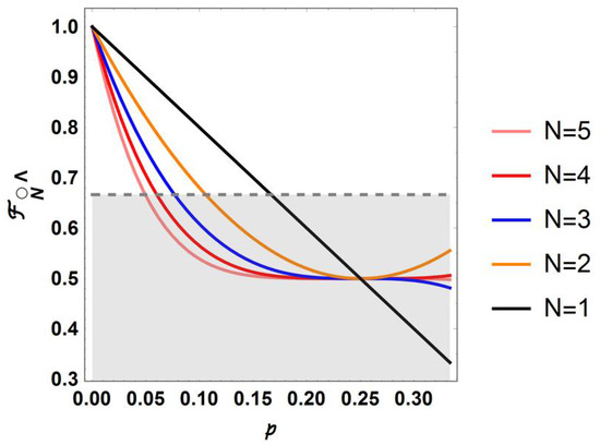
Figure 2.
Sequential fidelity as function of the number N of channels being applied, and p is the deformation strength in .
3. Quantum Teleportation Assisted by Indefinite Causal Order with Channels
In this section, we will consider a generalization of some variants of the process under indefinite causal order as they are presented in [7,22] by considering N channels in a superposition of causal orders. By applying N channels in a superposition of causal orders, we could have combinations with different orders. Thus, we will need a control state with such number of dimensions ( sets for the normal sequential order of gates ) to rule the application of each causal order:
For a definite causal order of teleportation channels given by the element in the symmetric group of permutations from the ordered case, it has the effect:
and symbolically corresponding to the control state . Then, the corresponding Kraus operators are:
where in the following, we will drop the tensor product symbol ⊗ in the sake of simplicity. Thus, the output for channels in superposition is given by:
Still, we can use the last formula to reach a simpler expression using combinatorics and then the properties of Pauli operators. In fact, noting that the sum in (14) includes all different values given to each , after they are permuted as distinguishable objects by and , it can be transformed into:
where is the number of scripts in equal to (). Sum over p runs on the distinguishable arrangements obtained with a fix number of operators departing from by means of a certain permutation . Then, the permutations among identical operators in each one of the four types are indistinguishable. There, . In such case, Formula (14) can be written as:
providing an easier formula for in terms of a definite number of sums and with the teleported state separated from the control state. From the properties of Pauli operators algebra, it is clear that both permutation terms besides in (15) becomes equal until a sign. In addition, each one becomes in the set . Thus, (15) becomes a mixed state obtained as a linear combination of syndromes and normally entangled with the control state.
Following to [7], then we select an adequate basis to perform a measurement on the control state: . Such a measurement post-selects the original symmetry of the teleported state mixed with the control and the imperfect entangled state. In such a basis, we hope to find a privileged state to stochastically maximize the fidelity with probability (assuming is a pure state). sets the probability of success of the process. If the measurement of control does not conduct to , then other undesired teleportation outcome will be obtained. Then, if the desired outcome is not obtained, we disregard the output state. The fidelity and the success probability are:
The process is depicted by Figure 3, where causal orders are considered to arrive to the pictorial representation of a complete superposition of causal orders on the right. Each causal order corresponds to one definite order in the application of channels ruled by the control state above it.

Figure 3.
causal order combinations for N identical teleportation channels finally conforming a superposition of it. Each one is ruled by the control state above.
4. Analysis of Quantum Teleportation Assisted by the First Indefinite Causal Orders
In the following section, we deal with the analysis for the increasing number of teleportation channels after to remark some outcomes for the case guiding the further analysis.
4.1. Teleportation with Teleportation Channels in an Indefinite Causal Order Superposition
For the case , it has been obtained in [22] that (16) reduces to:
then, a measurement on the control is made on the basis , being the supposed state maximizing . The corresponding probability to get that outcome becomes:
Note that the combination of the two first formulas gives the sequential case in (5). The other two terms correspond to the interference terms. First and third formulas can be demonstrated noting that:
This fact is not exclusive of the case . Due to the Pauli operators algebra and the regarding they are traceless (while, ), introducing (24) in (16) and (17), we note for that only the terms containing become different from zero. For , only the quadratic terms in and become different from zero. For the terms quadratic in , the additional condition is required in order to reduce the terms containing to the magnitude of , thus removing all reference of the teleported state.
In [7], it has been demonstrated that for the worst deformed state with still lets a perfect teleportation with probability . In fact, Figure 4 summarizes the findings for the fidelity considering the two families of measurements with (dashed orange lines) and (dashed blue lines). The sequential case with is reported as a continuous line black together with the single teleportation channel (continuous red line). Dashed blue and orange lines go folded from (two channels in definite causal order) nearest to the two sequential channels case in black to the outermost lines for (the evenly distributed control state) reaching in (blue for ) and (orange for ).
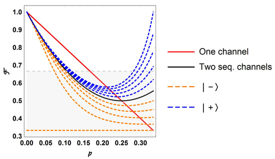
Figure 4.
Fidelity for the case of two channels in indefinite causal order as function of p. The blue dashed upper line corresponds to and reaching in .
For the case , [22] has shown that for different values of , other measurements are possible in order to achieve when giving and distributed as in the Figure 5 as function of . Thus, the best fidelities depend entirely from p (see the color-scale besides in Figure 5) but the corresponding values of go down far from (). The red dotted line is the threshold setting the minimum fidelity reached in the optimal case for , [22]. Thus, we conclude that for , the best state for the control is in order to maximize , despite only for and it is possible to approach . The last outstanding outcome for is a consequence of the two-folded interference introduced by the indefinite causal order together with the post-selection induced by the measurement which filters only constructive interference among the terms belonging to the original state.
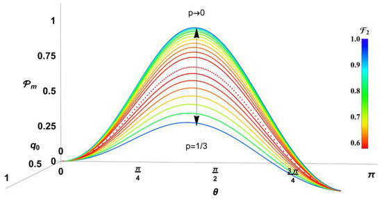
Figure 5.
Condensed outcomes for the case . The respective probability of measurements are included as function of and in ( in the optimal measurement). Fidelity depends entirely from p, and goes down while .
Fidelity (18) can be still analysed for independent values of . Figure 6 shows a numerical analysis to search the best possible fidelity (achieved for certain teleported state) for all possible and . The value of fidelity is represented in color in agreement with the color-scale bar besides. Figure 6a shows a cut from the entire plot showing the inner core where fidelity goes down (three parts are symmetric). The higher values of fidelity on the faces of polyhedron suggest that better solutions can be reached for other cases with unequal values of , particularly for the frontal face completely colored in blue in Figure 6. The case falls in the central red dashed division crossing the clearer core reflecting the outcome in Figure 4, where not good values of are inevitably obtained far from and . In addition, complementary information for such cases is given by in Figure 6b, the probability to reach the corresponding higher fidelity in each process assisted by an intermediate optimal measurement on the control qubit. The plot depicts disperse outcomes barely around of . Note that the computer process to obtain Figure 6a,b requires optimization on lots of parameters, thus requiring a considerable time of processing. The region was divided in points to perform such optimization. After, each point is reported as a colored sphere to fill the space in order to give a representation in color about the continuity of and . Such an approach gives a certain impression of blurring in the figures, but they are reported with the best precision available under numerical processing. Particularly, Figure 6b is a collage of colored dots due to is reported on an average basis, due the optimization was made on on the left. By performing a numerical statistics of our outcomes for each , we get an approximation to its statistical distribution included in the upper inset in Figure 6b. This distribution shows symmetric behavior around of as it could be expected for the numerical optimization.
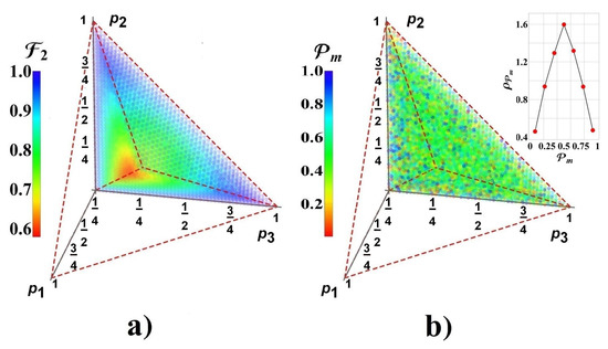
Figure 6.
(a) Best fidelity for the two-channels case as function of . Each point inside the polyhedron corresponds to their acceptable values and it is coloured in agreement with its fidelity value (see the color-scale besides); the cut of polyhedron region exhibits the inner structure; (b) The corresponding values for measurement probabilities denoting disperse values around . The upper inset confirms the statistical distribution exhibiting symmetry around .
4.2. Teleportation with an Increasing Number of Teleportation Channels in an iNdefinite Causal Order Superposition
Formula (15) exhibits the superposition of terms finally involving the states and while they become entangled with the control state . In the next sections, we deal with two cases of interest for the use of the teleportation algorithm under indefinite causal order.
4.2.1. Case
First, we will address with the case widely used in the literature for simplicity. In [7], it has been suggested that for having one of the following forms:
The teleportation fidelity becomes optimal. There, is the signature of the parity of each order . By considering (15) together with (25) and the control state with :
Then, we have developed the Formulas (14) and (16) with in (25) to get both and for . Those formulas have been plotted (they are not reported here because their complexity, despite they are included in the Appendix A), the outcomes are shown in Figure 7 showing that a perfect fidelity for is achieved when meets with the same parity to N (p is indicated in the color-scale besides). Despite, for the success probabilities decrease while N increases. For and , we get , thus becomes undefined in such a case. While the best election is the single teleportation channel, for , the assistance of the causal order becomes an alternative to enhance the fidelity of teleportation, particularly with channels.
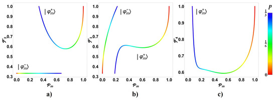
Figure 7.
Probability to obtain different values of fidelity when the measurement states or are applied for cases (a) , (b) and (c) . Color-scale bar depicts the respective value for p for .
Figure 8 again compares the fidelity versus p for both measurements with the corresponding sequential case showing the alternated optimization of as function of the parity of N and . Despite, the outcomes in Figure 6 suggest analysing the behavior of for independent values of .
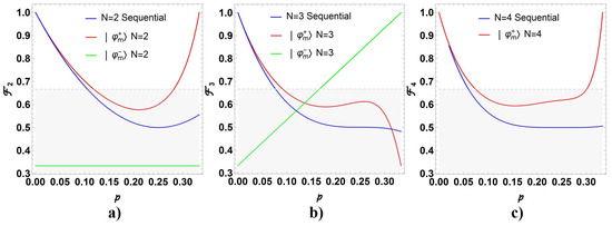
Figure 8.
Comparison of fidelity obtained when the channels are applied sequentially (blue) and with indefinite causal order depending on the measurement state (red) and (green), for the cases (a) , (b) , and (c) (in this last case, the fidelity becomes undefined for ).
4.2.2. Case ,
In some practical cases, the expected values for the entangled resource vary slightly from a perfect entangled state: for . Thus, the outcome described through Formula (15) becomes in this case (developing to first order for the factor there):
Note that under this approximation, becomes unaltered and separated from the system state. Thus, the optimal way to teleport the state implies to measure the control state considering . In the following, we assume such an optimal measurement made on the control state.
For the particular case where with , last formula can be written as:
Obtaining the totally depolarized state . Notice that it is only applicable for very large values of N (due to the assumption ). This aspect is advised in the Figure 7 where the fidelity drops more rapidly to when N grows around of .
In general, the probability and fidelity given in (27) will become respectively (developing to first order in ):
where was written as in (24). We are introduced the reduced parameters and the threshold probability to limit the validity of the current approximation (, ). We note in any case that the increasing of N worsens the fidelity. Note each term in the sum in (30) is non-negative, thus the fidelity becomes commonly reduced. Because only one of could be one at the time, then it is necessary in addition that two become zero to get . Otherwise, with a notable decreasing if N is large. The outcome in (29) exhibits a combination of the three error-syndromes reflected through the terms as function of . Thus, for each syndrome the best states being teleported are those closer to the eigenstates of , otherwise while several the teleportation capacity is widely reduced.
Considering with on the Bloch sphere: . Then, we analyze each syndrome and its impact on the fidelity through the quantity . As lower it becomes, higher becomes . Figure 9a shows the simple behavior of for each state on the Bloch sphere under each syndrome: ; ; and in such order. We have denoted as and to the eigenstates of (or ). Note the behavior commented in the previous paragraph.
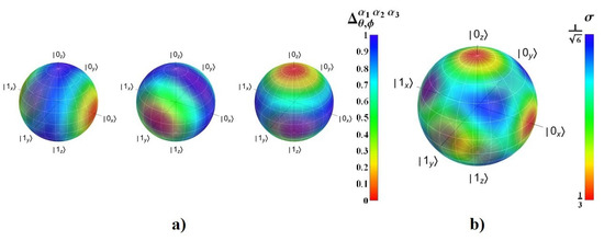
Despite, the most interesting issue is centered in the fact that the entanglement resource is normally unknown but with a tiny variation of through the deformation parameters . By calculating the average and the standard deviation of on the parameters :
We note that the average value of fidelity becomes independent from the state being teleported. While, the dispersion for on the values depends from the teleported state and it becomes lowest for the eigenstates of . In fact, the exact result for the case of is precisely (30) with such value in (1): , thus the values in (33) are scaled from it by a factor N. The reason is easily noticed, the in (27) obtained by linearization from (3) coincides with the sequential case (3) under linearization, so both cases exactly meet under the current limit. It implies that indefinite causal order procedure in teleportation becomes unpractical in this limit.
4.3. Notable Behavior on the Frontal Face of Parametric Region: Case
The behavior of on the frontal face () in Figure 6 can be now better advised in Figure 10. There, we have calculated numerically (for states covering the frontal face), the best fidelity obtained using two teleportation channels under indefinite causal order by taking the optimal measurement on the control state together with the best state able to be teleported. Thus, it represents naively the best possible scenario.
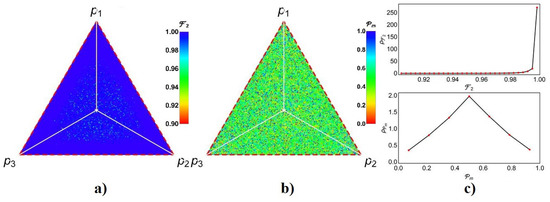
Figure 10.
Optimal fidelity using two teleportation channels in indefinite causal order followed by an appropriate measurement . (a) The best fidelity obtained for certain teleported state if optimal control measurement is obtained, (b) the probability of success for the last process, and (c) the statistical distribution for and .
In the last process, for each on the frontal face, we have additionally taken a sample of sets of values for (the initialization value for the control state for ), for and for the teleported state . Each value is used as initial condition to find a local maximum for the fidelity . Then, those values are used to predict the global maximum of for each point on the frontal face. Figure 10a shows the best fidelity on the face together with the statistical distribution of the fidelities on the frontal face in the upper image of Figure 10c, which suggests that could be obtained on the face always (the little dispersion with lower values of are due to the numerical procedure followed). The same follows for (Figure 10b,c lower) but denoting that such probabilities of success are centrally distributed around (note they are not the best probabilities because the process is centred on maximize . As in Figure 6, images in Figure 10 appear blurred due to the limited number of points considered because the time processing.
Nevertheless, the last fact is in reality a blind strategy. A more critical view of Formulas (18) and (19) and referring to [22] which numerically suggests that is related with the optimal case for the case . In fact, in such case, last formulas become reduced to:
Last formula explains the reason because the case is optimal for . Moreover, on the frontal face (then ), then (34) and (35) clearly become (by splitting the cases from , noting for the last case and the fact that we are dealing with pure states):
Thus, the last conditions make the teleportation optimal not only for but also for the entire cases on the frontal face, being independent from the teleported state. Nevertheless, the probability of success depends entirely from the values of (considering only the best case ). Figure 11 shows the distribution of on the frontal face (in some cases we will denote this probability by to state and arbitrary but fulfilling ), which ranges on . In fact, the case corresponds to the worst case for in the center of the face. We have constructed the norm on the frontal face to report such distribution. The mean and the standard deviation were calculated using such distribution.
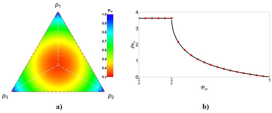
Figure 11.
(a) Values of on face, and (b) its corresponding statistical distribution for two teleportation channels in indefinite causal order.
In order to solve the cases for by including further teleportation channels under indefinite causal order, last analysis suggests for arbitrary N that the procurement of an analytical formula for (15) is in order at least for the case , implying :
and . As it was previously mentioned, factors generated by and are equal until a sign. In addition, they always evolve to or (easily depending on the parity of ). Thus, those factors and their signs state the introduction of syndromes on together with interference among them and the different orders. Such interference could be manipulated through the parameters .
Even so, this formula is not easy to address in order to get a simpler closed result because the sign introduced in the permutation with respect cannot be advised easily (see a parallel analysis in [8]). Nevertheless, we can still to analyse computationally the cases for the lowest values of N (analytical cases addressed by computer aided methods due to the factorial increasing number of terms). Thus, formulas for and for N larger than two have been obtained using a computational treatment. The formulas obtained in the analysis are reported in Appendix B. As in our previous discussion for the case in the Section 4.2.1, is obtained for all cases on the frontal face if the measurement in the indefinite causal order becomes for and for independently of the teleported state. Again, it is a consequence of the order interference due to the indefinite causal order together the post-selection induced by the measurement. For complementary cases using other measurement outcomes, we get depending from or still undefined, and additionally depending from the teleported state (see Appendix B).
5. An Alternative Procedure Introducing Weak Measurement
In spite of the previous outcomes, we guess the indefinite causal order could not work properly at any point inside of region depicted in the Figure 6. Nevertheless, due to the outcomes in [7] for the case and those exhibited in the Figure 6, the teleportation process assisted by indefinite causal order (at least for two channels) becomes optimal on and (the origin and the frontal face in Figure 6a). Then, we propose an alternative strategy beginning with a weak measurement on the entangled resource.
5.1. General Case for Assisted by a Weak Measurement
By considering first the following weak measurements on , we get the post-measurement states and their probabilities of occurrence:
which projects the entangled state on one of the two states or with probabilities or respectively. Each state is located on the origin or otherwise on the frontal face of the region in Figure 6. Then, if is obtained, the teleportation process can go as in the Figure 1, otherwise, if is obtained, we can try the teleportation assisted by indefinite causal order (at this point the reader could note that clearly, we need two entangled resources). We will come back to discuss the weak measurement strategy widely in the last section).
The entire process is depicted in the Figure 12, a schematic diagram of the process as it was originally proposed by [7]. Given certain state to teleport, we use certain entangled resource . It goes through the weak measurement in (40) to get with probability . Then we perform a single teleportation. Instead, by obtaining with probability , then we prepare a second entangled resource repeating with it the same procedure, if after of the weak measurement is obtained with probability , we disregard proceeding with a single teleportation using such state. Otherwise, if is obtained, we perform a two-channel teleportation assisted by indefinite causal order using the states previously obtained. There, the teleportation will become successful with probability , otherwise it becomes unsuccessful and we need disregard the process. Thus, the global probability of success is (there, corresponds to (37) with , renaming as , with ):
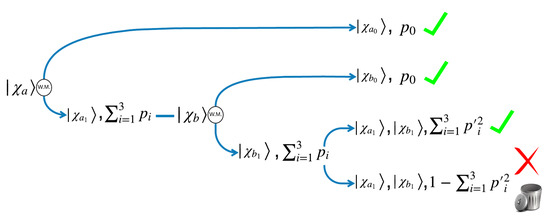
Figure 12.
Schematic teleportation process assisted by weak measurement.
The last function has been represented in the plots of Figure 13. For each initial set of the entangled resources (assumed identical), is plotted in color in agreement with the bar besides in the Figure 13a. One-third of the plot has shown, due to its symmetry, to exhibit its inner structure. The corresponding statistical distribution is obtained numerically in the Figure 13b by uniformly sampling the space in the figure on the left. The mean value of becomes 0.70 and their standard deviation 0.16.
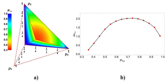
Figure 13.
Distribution of : (a) as function of , and (b) as statistical distribution by itself obtained numerically from the data of (a).
5.2. Cases for Assisted by a Weak Measurement
For , the procedure follows as in the previous section by introducing N imperfect entangled resources, (assumed identical for simplicity) but in each step, we decide if after of the weak measurement, the state is used to perform a single teleportation or if we continue the process of weak measurement N times on identical entangled resources to finally get as in the Figure 12. The corresponding situation is now depicted for the general case in the Figure 14. In this case, the global probability of success becomes:
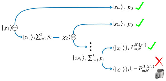
Figure 14.
Schematic teleportation process assisted by indefinite causal order using N-teleportation channels and weak measurement.
Inserting the formulas for in Appendix B (specialized for the frontal face and changing by ). Then, we can get the outcomes for global probability for the last cases with :
Now, we can visualize last outcomes for in Figure 15. Again, all the entangled states used for the teleportation process are assumed to be identical by simplicity. Figure 15a–c depict the probability to reach in the entire process represented in color. Each color bar shows the entire range of values for such probabilities on the graphs. According to the color, the blue zone represents the region where , observing for the case a larger blue area, suggesting still the goodness of increase the number of teleportation channels under indefinite causal order combined with post-measurement.
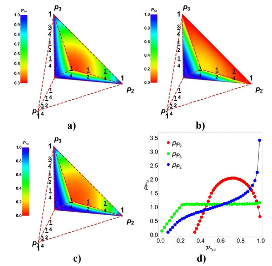
Figure 15.
(a–c) values of as function of , for and respectively. (d) Statistical distribution numerically obtained for and .
Figure 15d depicts a numerical analysis of statistical distribution for the cases . Note that for , all greater values for the probability occur almost evenly. For the case , it is observed a larger amount of success probabilities than failure probabilities compared with . Despite, and (because for there are a large distribution for medium success probabilities). In any case, the most successful outcomes of teleportation appears for .
6. Experimental Deployment of Teleportation with Indefinite Causal Order
In this section, we comment on some main experimental developments for a possible deployment of indefinite causal order in teleportation. We begin with the procedure to set the weak measurement used in Section 5.1. Afterwards, we set some elements and experimental developments to propose the implementation of the theoretical proposal before presented.
6.1. Implementation of Weak Measurement to Project
In Section 5.1, we stated the implementation of a weak measurement to project conveniently onto or . Despite, in the experimental approach, there are certain differences due to the resources been used. In this section, we present how to afford the weak measurement stated in (40). We use an ancilla qubit to do the measurement minimizing the impact on as is desired. In this implementation, we will use as a central resource the Toffoli gate. In order to prepare the stated properly for such measurement, we combine it with the ancilla. Then, we send the combined system into the circuit presented in Figure 16a. This circuit employs the Toffoli gate on channels for and a for together with the gate (already developed for ions [25,26] and photons [27]). In fact, it is well-known that Toffoli gate can be performed using gates and single-qubit gates [14] o by means of the Sleator–Weinfurter construction [28], despite other more efficient developments are known for ions [29] and photons [30]. Some single-qubit gates as Hadamard () and Not () are also used. In the following development, we write as the imperfect entangled resource (be aware that * not means complex conjugation). Thus, all necessary quantum gates have been experimentally developed in our days at least in quantum optics.
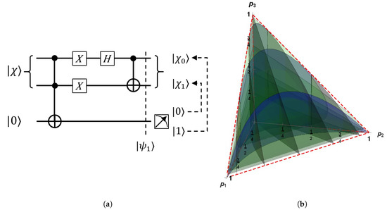
Figure 16.
(a) Quantum circuit generating the weak measurement on , and (b) contour plots for the map on the region between those probabilities and .
A direct calculation shows that this circuit performs the following transformation on into:
Just before of the projective measurement on the qubit a shown in the Figure 16a. Clearly, after measurement, two possible outcomes arise in the qubit a, while on qubits the outcomes are , respectively as in the Section 5.1, thus completing the weak measurement. The only difference with respect our previous development is that those coefficients are not the original . Despite this, in the event that such coefficients are unknown, this fact is not important, the really outstanding outcome is that this procedure projects the state into the perfect Bell state to perform the teleportation or otherwise on the frontal face if this resource is planned to be used under indefinite causal order and measurement (as it was previously depicted in the procedure of Section 5.1). Anyway, Figure 16b shows the contour plots of (red), (green) and (blue) in the region as a reference of the involved geometric transformations.
6.2. An Insight View about Teleportation Implementing Indefinite Causal Orders Experimentally with Light
Formula (1) regards the teleportation algorithm as a quantum communication channel. Despite this formula being a useful simplification for the theoretical analysis, it expresses the teleportation channel with the input and output through the same system, which is not precisely the real experimental situation. Then, as it was true for the original implementation of the original teleportation proposal [9] in [31], the deployment should be modified to have a correct approach to the theory. In this section we discuss an insight view into the experimental deployment together with indefinite causal order based on current techniques and experimental developments.
A possible implementation with light should to consider an initial state with at least three initial photons exhibiting each one at least a pair of quantum variables as polarization, frequency or spatial localization (-vector state) among others (as in the original experimental teleportation proposal [31]): , using polarization in the vertical direction as instance. Those photons should then be converted into five photons by splitting the last two into entangled pairs using Spontaneous Parametric Down Conversion (SPDC) [32] as instance, while the first state is arbitrarily rotated by a quartz polarization rotator (QPR) [33] -to generate the state to teleportate-: . After, five photons should be sent together into two alternative directions (through a dichroic beamsplitter—a splitting wavelength dependent—instead a polarization beamsplitter) coincidentally, not independently (it means five photons will travel through corresponding paths labeled by or ). This beamsplitter (BS) works as our control state superposing the two path states (the two causal orders further). Last effect should be solved based on the frequency of original photons which should be quantum generated to let a quantum splitting of all beams (or otherwise based on the previous generation of a state [34]). This necessary beamsplitter is still a cutting-edge technology. Such spatial quantization introduces an additional quantum variable thus converting the initial state into (removing the tensor product symbols for the sake of simplicity):
If additionally we introduce certain optical distortion in the SPDC, we get imperfect entangled states then changing each by . In the following, we will change by respectively for simplicity.
Note that teleportation is, in a certain sense, automatically generated due to the non-locality of the resource (or imperfectly by ), then collapsed on four adequate outcomes involving an additional correction as a function of those outcomes using classical communication (Figure 1a). In addition, for two sequential teleportation channels, the process can be achieved by post-measurement at the end of both processes. Nevertheless, the implementation of indefinite causal order in teleportation introduces additional challenges due to the connectivity of paths and measurements. In the process, it will be required the implementation of the gate, which has already been experimentally performed in optics [35,36].
Thus, Figure 17 depicts a possible implementation for two teleportation processes assisted by indefinite causal order. The first photon goes to the QRP and then the five photons go through the coordinated BS. The proposed process can be then followed in the Figure 17 with paths labeled by in green and in red. For simplicity, teleportation processes are assumed to perform measurements on the Bell states basis as in Figure 1b, thus avoiding the use of H and gates in the analysis. Due to the above construction (post-measurement and measurement assumed on the Bell basis), almost no gates are present in the process, just two gates stating the causal connections. At the end of each path, a semi-transparent mirror should mix again the paths (but not the polarization) by pairs into the basis for each photon i, in order to erase the information of the path followed. We labeled each path (or the information being carried on it) by (in case that photon carries the information of one of the complementary systems not containing the output of teleportation) remarking the path type followed ; the final belonging teleportation process ; and the number of the sequential qubit to be measured there: for the former input and for the correspondent to the first qubit of the original entangled resource. Instead, the final outputs are labeled by (). By following the color, the reader should easily identify each path considering additionally the effect of the intermediate use of gates which is discussed below.
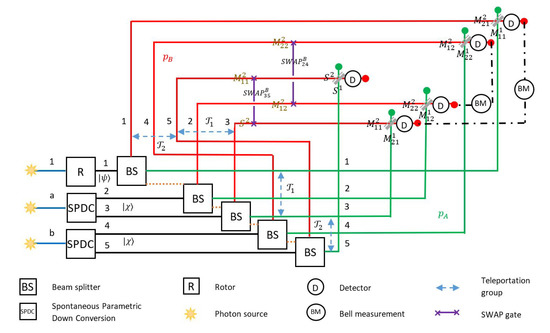
Figure 17.
Diagram for implementation of teleportation with causal ordering as it is discussed in the text. Photons are split on two different set of paths to superpose the two causal orders of two sequential teleportation process.
By ignoring first the gates in the Figure 17, we can realize that the circuit has not any effect. We have indicated each optical element described before. The dotted line connecting the ’s denotes the not independent functioning, all together should send the five photons on the green paths or on the red ones. States and are remarked on photons 1 and respectively. Each path (green or red) is labeled from 1 to 5 in agreement with the photon carried out. Blue arrow remarks the group of photons involved in each teleportation process or on each path (the first subscript in ): and respectively for the green paths, and and respectively for the red ones. On each path, we reported the associated label for each system or as it was depicted before. Note that brown labels correspond to the information being carried before of gates, while black labels are the final states reported there at the end of the path but before of the recombining in the semi-transparent mirrors. The reason for the gate between the paths 3 and 5 should be clear, we need to get the teleportation outputs on the same photon to generate the superposition of information. The gate on the red paths 2 and 4 exchanges the information on those paths in order to generate the superposition at the end among path information and with , thus mixing both. Note that the set of states in are those to be measured in the teleportation process (here in the Bell basis by pairs) in order to correct the output states. The reader should advise this process does not reproduce exactly that depicted by (1) because such formula assumes the measurements are internal operations generating a mixed state coming from the corresponding projections and corrections. In this approach, we have the possibility to measure only four qubits instead of eight. Despite, we will note this procedure still reproduces some of the main previous features analyzed. At the end of the process, each semi-transparent mirror (diagonal in grey) mixes the information on the states for each photon i on the red and green edges (with information or respectively -red and green-, not represented in the Figure 17). On the red edges, a detector first decides if the photon exits through them (they are the projective measurement on states in our development). In addition, a Bell measurement is then performed on each pair and in order to inquire the information codified in the output .
A direct but large calculation to expand (49) then applying the gates and projecting on was performed. Finally, this output was written in terms of to ease the identification of final successful measurements. If or , upon the measurement of and then the application of as correction, the output becomes faithfully in the following cases:
- If for all cases with a global successful probability of .
- If for the cases and with a global successful probability of .
This clearly resembles our main outcomes. For the second case, other measurement outcomes give imperfect teleportation thus rearranging the success probabilities with respect of those in our theoretical development. Thus, alternative experimental proposals should be developed to approach them into the ideal case considered in our theoretical results.
7. Conclusions
Quantum teleportation has an important role in quantum processing for the transmission of quantum information, nevertheless, there are possible issues on the entangled resource assisting the teleportation process mainly related to its maintenance and precise generation. It introduces imprecision in the teleported state. In this work, the implementation of indefinite causal order has been studied in order to propose an improved scheme to tackle such imprecision on the entangled state when it is combined with the measurement of the control assessing it.
The analysis for the redundant case where quantum channels are simply applied sequentially (assumed as identical) shows that the number N of channels applied, rapidly decreases the fidelity converging to the maximal depolarization of the teleported state thus obtaining . By modifying the process under indefinite causal order for two or more teleportation channels as it was proposed by [7] and later discussed in [22], we advise advantages on the quantum fidelity of the teleported state for the first values N of sequential teleportation channels. From the outcomes, a categorization was performed to analyze the effects on the entangled state, thus obtaining a surprising enhancement for the most imperfect entangled resource, with the absence of the ideal entangled resource , and still for near regions of it with when N increases. Notably, in the first case, it is possible to obtain a perfect teleportation process with . However, when N increases, the principal downside is the reduction of the probability of successful measurement , which decreases drastically as N increases.
In order to improve the global probability of success, we have proposed the combined use of weak measurement to first projecting the entangled resource to either with or with , where the indefinite causal order generates the most notable enhancements. In such cases, is obtained always and is improved. Those notable processes are possible as for pure as for mixed states [8]. A remarkable aspect is that for such a notable case the outcome is independent of the teleported state.
Finally, a more detailed process for the weak measurement (first barely discussed in the initial presentation) is after detailed and oriented to the practical implementation in terms of the current experimental developments for light and matter. The development of a Toffoli gate is advised as central in the implementation. In addition, an introductory analysis for a possible experimental implementation has been included for the teleportation process under indefinite causal order using two teleportation channels. Such an approach is still imperfect and not optimal. Despite this, it reproduces the main features found in our development. In the proposal, recent experiments and technological developments in optics become central, particularly the implementation of the gate and the generation of states. A valuable aspect being noticed is the use of post-measurement in the teleportation process. Additional theoretical and experimental developments should still improve the vast possibilities of indefinite causal order in the teleportation research field.
Author Contributions
C.C.-I. performed the research related with the analysis of indefinite causal order using 2 channels setting the structure for the further research. Both authors performed the computer algorithms to reproduce the output states after of indefinite causal orders. F.D. performed the theoretical development of indefinite causal order using N channels. C.C.-I. contributed in the development of computer simulations and computer graphics in the entire manuscript. C.C.-I. perform the research about the feasibility of indefinite causal order using the current technologies. F.D. developed the experimental proposal to implement indefinite causal order in Section 6.2. All authors contributed evenly in the writing of the manuscript. All authors have read and agreed to the published version of the manuscript.
Funding
This research received no external funding.
Acknowledgments
F.D. acknowledges to Jesus Ramírez Joachín his taught and thoroughly discussions in combinatorics during 1982, without which some parts of this work will not be possible. Both authors acknowledge the economic support to publish this article to the School of Engineering and Science from Tecnologico de Monterrey. The support of CONACYT is also acknowledged.
Conflicts of Interest
The authors declare no conflict of interest.
Appendix A. Formulas for and for the Case
Formulas for the fidelity and the success probability as the number of channels in indefinite causal order increases when have been obtained. For the case , when the outcomes are:
and for the case when , the expressions become:
For the case , when the outcomes are:
and for the case when , we get:
For the case , when we get , thus becomes undefined in such case, while for the case when , we get the expressions:
Appendix B. Formulas for and for the Case
In this section, formulas for and when the entangled state has different values for and (note they are restricted to the frontal face of the parametric space) and the measurement of the control state is either or . In those results, the angles and corresponds to the state being teleported (), thus meaning a dependence of those values on this state. For the case , with the privileged measurement state as , the expressions become:
and with the privileged state as , the corresponding expressions are:
For the case , with the privileged measurement state as , the outcomes are:
while, with the privileged state as , they become:
Finally, for the case , with the privileged measurement state as , then:
and if the privileged state is , then we get , thus gets undetermined.
References
- Ebler, C.; Salek, S.; Chiribella, G. Enhanced Communication with the Assistance of Indefinite Causal Order. Phys. Rev. Lett. 2017, 120, 120502. [Google Scholar]
- Chiribella, G.; Banik, M.; Bhattacharya, S.S.; Guha, T.; Alimuddin, M.; Roy, A.; Saha, S.; Agrawal, S.; Kar, G. Indefinite causal order enables perfect quantum communication with zero capacity channel. arXiv 2018, arXiv:1810.10457v2. [Google Scholar]
- Goswami, K.; Cao, Y.; Paz-Silva, G.A.; Romero, J.; White, A. Communicating via ignorance. arXiv 2019, arXiv:1807.07383v3. [Google Scholar]
- Procopio, L.M.; Moqanaki, A.; Araújo, M.; Costa, F.; Calafell, I.A.; Dowd, E.G.; Hamel, D.R.; Rozema, L.A.; Brukner, C.; Walther, P. Experimental superposition of orders of quantum gates. Nat. Commun. 2015, 6, 7913. [Google Scholar]
- Procopio, L.M.; Delgado, F.; Enríquez, M.; Belabas, N.; Levenson, J.A. Communication enhancement through quantum coherent control of N channels in an indefinite causal-order scenario. Entropy 2019, 21, 1012. [Google Scholar]
- Procopio, L.M.; Delgado, F.; Enríquez, M.; Belabas, N.; Levenson, J. A Sending classical information via three noisy channels in superposition of causal orders. Phys. Rev. A 2020, 101, 012346. [Google Scholar]
- Mukhopadhyay, C.; Pati, A.K. Superposition of causal order enables perfect quantum teleportation with very noisy singlets. J. Phys. Commun. 2020. [Google Scholar] [CrossRef]
- Delgado, F.; Cardoso, F. Performance characterization of Pauli channels assisted by indefinite causal order and post-measurement. Quantum Inf. Comput. 2020, 20, 1261–1280. [Google Scholar]
- Bennett, C.H.; Wiesner, S.J. Communication via One- and Two-Particle Operators on Einstein-Podolsky-Rosen States. Phys. Rev. Lett. 1992, 69, 2881–2884. [Google Scholar]
- Bennett, C.H.; Brassard, G.; Crépeau, C.; Jozsa, R.; Peres, A.; Wootters, W.K. Teleporting an Unknown Quantum State via Dual Classical and Einstein-Podolsky-Rosen Channels. Phys. Rev. Lett. 1993, 70, 1895. [Google Scholar]
- Delgado, F. Teleportation based on control of anisotropic Ising interaction in three dimensions. JPCS 2015, 624, 012006. [Google Scholar]
- Yan, F.; Yang, L. Economical teleportation of multiparticle quantum state. Il Nuovo C. B 2003, 118, 79. [Google Scholar]
- Metcalf, B.J.; Spring, J.B.; Humphreys, P.C.; Thomas-Peter, N.; Barbieri, M.; Kolthammer, W.S.; Jin, X.-M.; Langford, N.K.; Kundys, F.; Gates, J.C.; et al. Quantum teleportation on a photonic chip. Nat. Photonics 2014, 8, 770. [Google Scholar]
- Nielsen, M.A.; Knill, E.; Laflamme, R. Complete quantum teleportation using nuclear magnetic resonance. Nature 1998, 396, 52–55. [Google Scholar]
- Delgado, F. Teleportation algorithm settled in a resonant cavity using non-local gates. In Quantum Information and Measurement; OSA Technical Digest: Rome, Italy, 2019. [Google Scholar]
- Bouwmeester, D.; Pan, J.; Mattle, K.; Eibl, M.; Weinfurter, H.; Zeilinger, A. Experimental quantum teleportation. Nature 1997, 390, 575–579. [Google Scholar]
- Ursin, R.; Jennewein, T.; Aspelmeyer, M.; Kaltenbaek, R.; Lindenthal, M.; Walther, P.; Zeilinger, A. Quantum teleportation across the Danube. Nature 2004, 430, 849. [Google Scholar]
- Ma, X.S.; Herbst, T.; Scheidl, T.; Wang, D.; Kropatschek, S.; Naylor, W.; Wittmann, B.; Mech, A.; Kofler, J.; Anisimova, E.; et al. Quantum teleportation over 143 kilometres using active feed-forward. Nature 2012, 489, 269–273. [Google Scholar]
- Luo, Y.H.; Zhong, H.S.; Erhard, M.; Wang, X.L.; Peng, L.C.; Krenn, M.; Jiang, X.; Li, L.; Liu, N.-L.; Lu, C.-Y.; et al. Quantum Teleportation in High Dimensions. Phys. Rev. Lett. 2019, 123, 070505. [Google Scholar]
- Caleffi, M.; Cacciapuoti, A.S. Quantum Switch for the Quantum Internet: Noiseless Communications through Noisy Channels. IEEE J. Sel. Areas Commun. 2020, 38, 575. [Google Scholar]
- Yin, J.; Ren, J.G.; Lu, H.; Cao, Y.; Yong, H.L.; Wu, Y.P.; Liu, C.; Liao, S.K.; Zhou, F.; Jiang, Y.; et al. Quantum teleportation and entanglement distribution over 100-kilometre free-space channels. Nature 2012, 488, 185–188. [Google Scholar]
- Cardoso, C.; Delgado, F. Featuring causal order in teleportation of two quantum teleportation channels. J. Phys. Conf. Ser. 2020, 1540, 012024. [Google Scholar]
- Bowen, G.; Bose, S. Teleportation as a Depolarizing Quantum Channel, Relative Entropy, and Classical Capacity. Phys. Rev. Lett. 2001, 87, 267901. [Google Scholar] [PubMed]
- Petz, D. Quantum Information Theory and Quantum Statistics; Springer: Berlin/Heidelberg, Germany, 2008. [Google Scholar]
- Schmidt-Kaler, F.; Häffner, H.; Riebe, M.; Gulde, S.; Lancaster, G.P.; Deuschle, T.; Becher, C.; Roos, C.F.; Eschner, J.; Blatt, R. Realization of the Cirac–Zoller controlled-NOT quantum gate. Nature 2003, 422, 408–411. [Google Scholar] [PubMed]
- Maslov, D. Basic circuit compilation techniques for an ion-trap quantum machine. New J. Phys. 2017, 19, 023035. [Google Scholar]
- Lopes, J.-H.; Soares, W.-C.; Bertúlio de Lima, B.; Caetano, D.P.; Askery, C. Linear optical CNOT gate with orbital angular momentum and polarization. Quantum Inf. Process. 2019, 18, 256. [Google Scholar]
- Sleator, T.; Weinfurter, H. Elementary gates for quantum computation. Phys. Rev. Lett. 1995, 74, 4087. [Google Scholar]
- Monz, T.; Kim, K.; Hänsel, W.; Riebe, M.; Villar, A.-S.; Schindler, P.; Chwalla, M.; Hennrich, M.; Blatt, R. Realization of the Quantum Toffoli Gate with Trapped Ions. Phys. Rev. Lett. 2009, 102, 040501. [Google Scholar]
- Huang, H.L.; Bao, W.S.; Li, T.; Li, F.G.; Fu, X.Q.; Zhang, S.; Zhang, H.L.; Wang, X. Deterministic linear optical quantum Toffoli gate. Phys. Lett. A 2017, 381, 2673–2676. [Google Scholar]
- Boschi, D.; Branca, S.; De Martini, F.; Hardy, L.; Popescu, S. Experimental Realization of Teleporting an Unknown Pure Quantum State via Dual Classical and Einstein-Podolsky-Rosen Channels. Phys. Rev. Lett. 1998, 80, 1121. [Google Scholar]
- Boyd, R. Nonlinear Optics; Academic Press: Rochester, NY, USA, 2018. [Google Scholar]
- Bass, M.; DeCusatis, C.; Enoch, J.; Lakshminarayanan, V.; Li, G.; MacDonald, C.; Mahajan, V.; Van Stryland, E. Handbook of Optics, 3rd ed.; McGraw-Hill Professiona: New York, NY, USA, 2009; Volume 1, pp. 3.46–3.61. [Google Scholar]
- Erhard, M.; Malik, M.; Krenn, M.; Zeilinger, A. Experimental Greenberger–Horne–Zeilinger entanglement beyond qubits. Nat. Photonics 2018, 12, 759–764. [Google Scholar]
- Zhu, M.; Ye, L. Implementation of swap gate and Fredkin gate using linear optical elements. Int. J. Quantum Inf. 2013, 11, 1350031. [Google Scholar]
- Ono, T.; Okamoto, R.; Tanida1, M.; Hofmann, H.; Takeuchi, S. Implementation of a quantum controlled-SWAP gate with photonic circuits. Sci. Rep. 2017, 7, 45353. [Google Scholar] [PubMed]
Publisher’s Note: MDPI stays neutral with regard to jurisdictional claims in published maps and institutional affiliations. |
© 2020 by the authors. Licensee MDPI, Basel, Switzerland. This article is an open access article distributed under the terms and conditions of the Creative Commons Attribution (CC BY) license (http://creativecommons.org/licenses/by/4.0/).