Abstract
A triangular mesh obtained by scanning 3D models typically contains holes. We present an effective technique for filling a hole in a triangular mesh in geometric modeling. Simple triangulation of a hole is refined and remeshed iteratively to generate an initial patch. The generated patch is then enhanced to become a target patch by minimizing the variation of principal curvatures. In discrete approximation, this produces a third-order Laplacian system of sparse symmetric positive definite matrix, and the symmetry can efficiently be used to find the robust solutions to the given Laplacian system. Laplacian smoothing of the target patch is defined as a source patch. The shape difference between two corresponding vertices of the source and the target patches is measured in terms of Euclidean distance and curvature variation. On the basis of the shape difference and a user-specified control parameter, different blending weights are determined for each vertex, and the final patch is generated by blending two patches. We demonstrate the effectiveness of our technique by discussing several examples. The experimental results show that our technique can effectively restore salient geometric features of the original shape.
1. Introduction
Owing to their simplicity and hardware-accelerated rendering facility, triangular meshes have been widely used for representing the shape of three-dimensional (3D) objects in computer graphics and real-time 3D applications. Even though there exist many advanced modeling techniques, it is still a tedious and time-consuming task to create a 3D model from a scratch using triangle mesh. Recent advances in 3D scanning technology have made it easy to obtain the shape of a 3D object and thus triangle meshes have become essential in reverse engineering, such as ergonomic product design and dental CAD. However, the scanned data set cannot be directly used and requires post-processing steps because it contains several artifacts such as holes, gaps, self-intersections, and handles. Among these artifacts, holes are quite common and are caused mainly by occlusions, accessibility limitations, and surface properties []. Figure 1a shows a typical artifact (in purple) encountered in a 3D scanning process and a patch filling the hole is shown in Figure 1b.
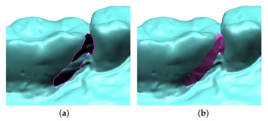
Figure 1.
Accessibility limitation of an oral 3D scanner results in (a) a hole in the scanned model. (b) The artifact is repaired by a hole-filling technique.
Over several decades, various types of hole-filling techniques have been developed for triangular meshes. Most hole-filling algorithms generate a hole patch that is smoothly connected with the hole boundary. However, they do not provide the user with the additional flexibility of controlling the shape of the generated patch. For example, the hole patch in Figure 1b is generated by solving a complex Laplacian system; thus, it is difficult to control the resulting shape as desired.
In this paper, we present a simple and effective technique for generating a hole patch in a triangular mesh and controlling its shape. The overall process of our method is shown in Figure 2. First, a hole is detected in a triangular mesh by searching closed boundary edges (Figure 2a), and simple triangulation fills the hole without additional vertices (Figure 2b). Subsequently, refinement and remeshing are applied iteratively to produce an initial hole patch (Figure 2c), and two different patches are constructed by Laplacian smoothing and minimizing curvature variation (Figure 2d). We select the patch generated by Laplacian smoothing for source patch and the other for target patch and measure the shape difference between them. The final hole patch is generated by blending the source and the target patches on the basis of the shape difference and a user-specified blending parameter. The result of the hole patch generated by using our method is shown in Figure 2e, where shape features, such as concavity and convexity, are easily exaggerated by a user’s control parameter.
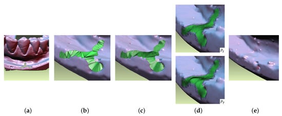
Figure 2.
Overview of the proposed algorithm. (a) a hole is detected in a triangular mesh by searching closed boundary edges, (b) simple triangulation fills the hole without additional vertices, (c) refinement and remeshing are applied iteratively to produce an initial hole patch, (d) two different patches are constructed by Laplacian smoothing and minimizing curvature variation, (e) the result of the hole patch generated by using our method.
The main contributions of our method can be summarized as follows:
- Robustness: Our method is based on the remeshing followed by fairing technique, which guarantees the robust solutions to symmetric Laplacian system without self-intersections. Therefore, our method can robustly be used for filling holes with arbitrary sizes and shapes.
- Effectiveness: By analyzing the shape difference between the source and the target patches, salient features, such as convexity and concavity, can be exaggerated or reduced in the resulting patch.
- Controllability: Our system provides the user with a shape control parameter. The user can interactively modify the hole patch until the desired shape is obtained.
The remainder of this paper is organized as follows. Section 2 reviews some related recent work on hole filling in triangular meshes. Section 3 details the construction of a source patch and a target patch by minimizing fairness energy. The parametric blending of two patches is then presented in Section 4, and experimental results are presented in Section 5. Finally, we conclude the paper and mention the scope for future work in Section 6.
2. Related Work
Barequet et al. [] proposed an algorithm for filling holes and gaps in polygon mesh. This algorithm is based on dynamic programming and later became a basic building block for other mesh repair techniques [,,,]. However, this method produces rough hole patches because the smoothness around the hole boundary is not considered. Pfeifle et al. [] constructed smooth patches that filled the holes in a piecewise polynomial surface using Delaunay triangulation and refinement. Liepa et al. [] proposed an umbrella operator for mesh fairing and constructed a hole patch with a density of triangles similar to that of the neighborhood of the hole. However, this method, employed in later works [,], requires a long processing time for filling large holes because of its time complexity, .
Chen et al. [,] presented a sharpness-dependent hole-filling method. They constructed an initial patch using radial basis interpolation. If sharp features exist around the hole, they enhance these features by applying Bayesian classification [] and a sharpness-dependent filter []. However, it is difficult to select the correct filter parameters to prevent undesired sharp features []. Zhao et al. [] constructed an initial patch filling of highly curved holes using the advancing front mesh (AFM) technique [] and improved the initial patch by solving the Poisson equation with Dirichlet boundary conditions [].
Pernot et al. [] employed Delaunay triangulation to generate an initial hole patch and optimized its shape while satisfying the tangency and curvature blending condition with the surrounding region. However, their method is not suitable for filling highly curved holes. Branch et al. [] and Xiao et al. [] sampled neighboring vertices of the hole boundary and created a hole patch using an (RBF) interpolator. These approaches produce plausible patches; however, additional controls, such as bulge and exaggeration are not possible.
Freeform surfaces have been employed for hole filling in polygon meshes. Charles et al. [] used cubic triangular spline patches for filling holes in a polygon mesh. Li et al. [] presented a hole-filling method for preserving sharp features. Their method includes locating incomplete feature curves around the hole boundary and generating a polynomial blending curve that smoothly connects feature curves. Then, two split sub-holes are filled by using a Bezier–Lagrange hybrid patch while guaranteeing smoothness around the hole boundary. Wang et al. [] also focused on preserving features. They proposed an automatic feature-preserving hole-filling framework for reconstructing missing corners and sharp edges. Fortes et al. [] proposed a surface reconstruction and hole-filling scheme based on a network of parallel and/or orthogonal curves. However, their method is more suitable for CAD models than for scanned triangular meshes.
3. Construction of Hole Patches
This section presents the construction of two hole patches that are used for the source patch and target patch.
3.1. Triangulation of Hole Boundary
Typically, two triangles share an edge, and a boundary edge is shared by a single triangle. A hole is a closed loop consisting of boundary edges. In this study, we employ a half-edge data structure [] for representing the triangle mesh, and thus holes and their neighboring vertices are easily detected in runtime.
Let be the vertices consisting of a hole boundary. By recursively connecting two vertices and with the smallest angle , we can triangulate a hole boundary. The triangulation of the hole boundary is shown in Figure 3a. Our method is similar to the AFM method [] but does not require preprocessing, such as hole contour cleaning []. Our triangulation may contain self-intersections for the complex and highly curved hole boundary; however, this problem can be automatically resolved by subsequent incremental remeshing and fairing stages.
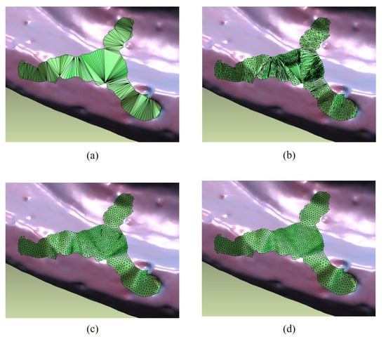
Figure 3.
Process of incremental remeshing: (a) initial triangulation, (b) first iteration, (c) third iteration, (d) fifth iteration.
3.2. Incremental Remeshing
As shown in Figure 3a, the initial triangulation is coarse and anisotropic. Moreover, the density of the triangles does not fit to the neighborhood of the hole boundary. To resolve this problem and improve its quality, we apply an incremental remeshing technique [,,] to the initial triangulation.
Algorithm 1 shows each step of the incremental remeshing technique. It takes the target edge length l as input and sets and values for the lower and upper bounds, respectively. Each edge longer than is split into two edges by adding a vertex (in Step 2). Edges shorter than are collapsed by merging two incident vertices unless the collapse does not generate new edges longer than (in Step 3). In general, a regular triangle mesh has valences of 6 and 4 for interior vertices and boundary vertices, respectively. We apply an edge-flipping operation to improve mesh regularity (in Step 4) and adjust the vertex positions to obtain isotropic triangles (in Step 5). We repeat these steps until all edge lengths are less than the . Self-intersections in initial triangulation can be removed by repeating these steps.
The intermediate results of iteratively applying incremental remeshing steps are shown in Figure 3b–d. As shown in Figure 3d, incremental remeshing generates a plausible hole patch; however, this patch does not reflect geometric information around the hole at all.
| Algorithm 1 Incremental remeshing |
|
3.3. Source and Target Patches
Let be the hole patch generated by incremental remeshing technique. must be further processed to create source and target patches. First, we explain how to construct a target patch , which is obtained by minimizing curvature variations on . Let be a continuous parametric surface. The minimum variation surface can be obtained by minimizing the variation of curvature represented by []:
where and denote principal curvatures, and and the corresponding principal directions. The corresponding Euler–Lagrange PDE is in D, where is the Laplacian operator. By linearlization followed by discretization, based on finite difference or finite element [,,], Equation (1) yields the following Laplace system for a triangle mesh:
where L denotes the discrete Laplacian matrix, is the vector of the free (unknown) vertex coordinates, and is the vector of the constrained vertex coordinates representing the boundary condition. For a minimum-variation surface, the boundary condition can be realized by fixing the positions of the two rings of the boundary vertices, as shown in Figure 4c. We employ the cotangent discretization [] for Laplacian matrix L. Because L is sparse and symmetric positive definite, the solution to the Laplace system in Equation (2) can be efficiently found by Cholesky factorization [].
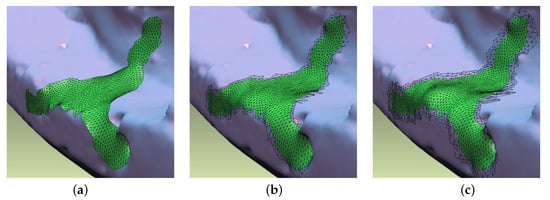
Figure 4.
Hole patches generated by (a) minimizing membrane energy (), (b) minimizing thin-plate energy (), and (c) minimizing curvature variation energy ().
The target patch constructed by this is shown in Figure 5b. Instead of minimizing the variation of curvature, we can minimize membrane energy or thin-plate energy, each of which produces a patch with a minimum area or minimum sum of curvature. In this study, we take a minimum variation patch as a target patch because it considers the shape of a wider area around a hole than other methods.
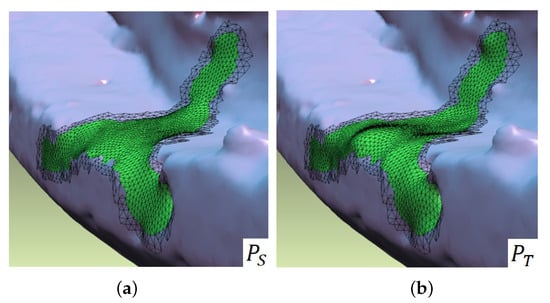
Figure 5.
Two hole patches to be blended: (a) Source patch , and (b) target patch .
Next, we create a source patch . For this, we apply Laplacian smoothing to . Let be the position of the i-th vertex of . Then, the new position of can be computed by
where denotes one ring vertex of , and is the edge weight connecting two vertices and . Cotangent weights are commonly used and can be computed by []
where and are the angles shown in Figure 6. As shown in Figure 5a, the source patch is generated by applying Laplacian smoothing.
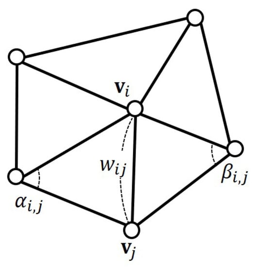
Figure 6.
Cotangent weight for Laplacian smoothing.
4. Parametric Blending of Hole Patches
The shape of the target patch might be unsatisfactory even though it contains more geometric details than the source patch. In this case, the user wants to change the shape of the hole patch. However, it is difficult to control the shape of a hole patch because it is determined by the solution to Equation (2).
In this section, we present an effective method for controlling the shape of a hole patch. On the basis of the shape difference between the source and target patches, we assign different weights to each vertex. These weights are used to generate the desired hole patch, where salient features are exaggerated by blending the source and target patches.
4.1. Shape Difference
There exists a one-to-one correspondence of vertices between the source patch and the target patch . Let and be the corresponding vertices between the two patches. First, we define the shape difference between and by using discrete mean curvature and Euclidean distance. Let and denote the mean curvature difference and the Euclidean distance between and , respectively. Then, the shape difference can be computed by
where , and are the minimum and the maximum of curvature difference, respectively, and and are the Euclidean distances. The shape difference can be controlled by user-specified parameter . For example, the shape difference is completely determined by the curvature difference if and by the Euclidean distance if . In Figure 7, the color-coded shape difference is shown between and .
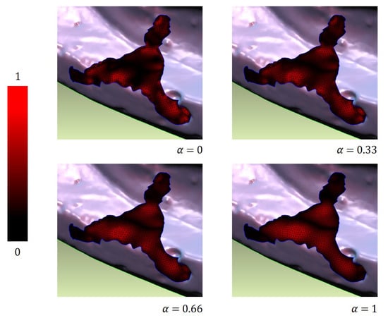
Figure 7.
Color-coded shape difference between and for different values of .
4.2. Blending Hole Patches
Let w be a user-specified blending weight . Based on the one-to-one correspondence between and , simple linear blending can generate a new patch . However, the uniform blending weight w is not sufficient to produce a hole patch with exaggerated geometric features. To overcome this limitation, we replace the uniform blending weight w with the per-vertex blending weight by employing the shape difference between two vertices. The per-vertex blending weight can then be computed by
where w is the user-specified uniform weight, and is the shape difference between two vertices, and . In general, large shape differences imply that the corresponding vertices can be a salient feature and need to be exaggerated by a large blending weight. From this observation, Equation (3) produces the blending weights if and if . In Figure 8, the per-vertex blending weights are shown depending on different shape differences . Finally, each pair of the corresponding vertices is blended by per-vertex weight and produces the resulting hole patch.
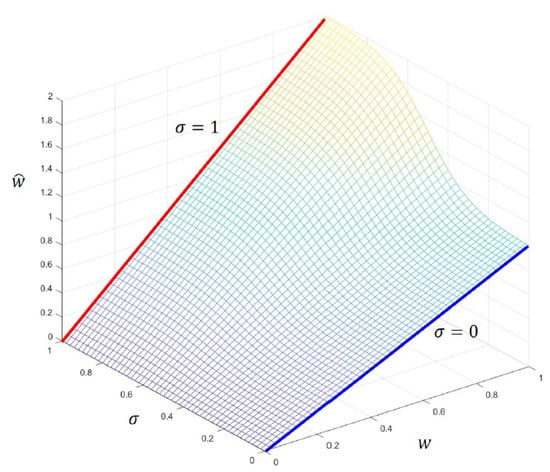
Figure 8.
Per-vertex blending weight is determined by a user-specified blending parameter w and a shape difference .
5. Experimental Results
The proposed technique was implemented on a PC with an Intel i7-9700F CPU, 16GB main memory, and an NVIDIA RTX 2060 graphics card, using the C++ language. Various 3D models with different hole shapes and sizes were used to demonstrate the effectiveness of the proposed technique.
The hole-filling results for four different models are shown in Figure 9. The first column shows the original models with various holes, and the second column shows the target hole patches () obtained by minimizing curvature variation (). Note that the target hole patches are also plausible to some extent. However, they lack geometric details in the region of the hole center. As shown in the third column, in Figure 9, our method provides the user with additional control to enhance the quality of the generated hole patch. From the shape analysis between the source patch and the target patch, the scaled blending weight for each vertex is computed, and these weights are used to exaggerate salient geometric features effectively.
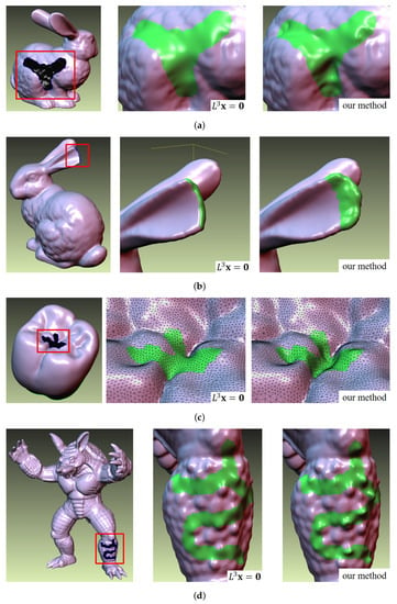
Figure 9.
Four examples with complex holes. (a) Left: a bunny model; middle: minimizing curvature variation(), right: shape-difference-based blending(our method), . (b) Left: a bunny model; middle: ; right: our method, . (c) Left: a molar model; middle: , right: our method, . (d): Left: an armadillo model; middle: ; right: our method, .
As shown in Figure 9a, we considered both the Euclidean distance and curvature difference by setting , and thus convexity and concavity are exaggerated in the final blending result. As shown in Figure 9b, we mainly considered the Euclidean distance in the shape difference. In this case, the Euclidean distances of the vertices in the boundary region are small, whereas those in the center region are relatively large. Thus, we can obtain the bulging effect in the center region while restoring the shape of the bunny ear. The sunken hole in Figure 9c is quite challenging because there might be large shape variations in the missing region. Compared to the target patch, our method successfully generates a hole patch with sufficient geometric details. In Figure 9d, we exaggerated the bumps in the target patch by considering a greater curvature difference rather than the Euclidean distance.
Our method supports real-time control for hole-patch generation and blending. As the user changes the blending weight w, only the per-vertex blending weight is recomputed and the hole patch is updated by simple linear blending. Because the source and target patches do not need to be updated, they can be constructed in the pre-processing step. Table 1 lists the computation time required to generate the target patch by solving Equation (2) and the source patch by applying Laplacian smoothing to the target patch. For all examples, per-vertex blending was performed within a millisecond. As shown in Figure 10, the computation time linearly increases depending on the number of vertices constituting the hole patch.

Table 1.
Number of vertices on hole boundary and int the hole patch, and the computation time (in ms) for generating the patches for each example.
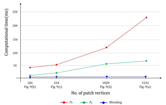
Figure 10.
Computational time for creating a hole patch for different hole sizes.
6. Conclusions and Future Work
We present an effective technique for filling a hole in a triangular mesh based on shape differences. The target patch is generated by minimizing the curvature variation of the initial hole patch, and the source patch is generated by applying Laplacian smoothing to the target patch. By employing Euclidean distance and curvature difference, we defined the shape difference between two vertices. Based on the shape difference, the per-vertex blending weight is computed, and these weights are used to blend the source patch and target patch. The experimental results show that per-vertex blending weight can exaggerate salient features, such as convexity and concavity, and we demonstrated the effectiveness of our method by comparing our hole-filling results with those of existing methods.
For a large hole, the shape difference in the hole center tends to be quite small; thus, it is difficult to reconstruct the geometric details of a hole center (see Figure 11). To resolve this limitation, we plan to determine how to transfer shape details outside a hole to the generated hole patch.
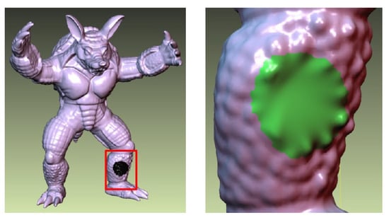
Figure 11.
Limitation of our method caused by small shape differences in the center of a large hole.
Author Contributions
J.-H.P. and S.P. conceived and designed the experiments; J.-H.P. implemented the proposed technique and performed the experiments; S.P. and S.-H.Y. wrote the paper. All authors have read and agreed to the published version of the manuscript.
Funding
This research was supported by Basic Science Research Program through the National Research Foundation of Korea (NRF) funded by Ministry of Education (No. NRF-2018R1D1A17048036, No. NRF-2020X1A3A1093880).
Conflicts of Interest
The authors declare no conflict of interest.
References
- Branch, J.; Prieto, F.; Boulanger, P. A hole-filling algorithm for triangular meshes using local radial basis function. In Proceedings of the 15th International Meshing Roundtable, Birmingham, AL, USA, 17–20 September 2006; Springer: Berlin/Heidelberg, Germany, 2006; pp. 411–431. [Google Scholar]
- Barequet, G.; Sharir, M. Filling gaps in the boundary of a polyhedron. Comput. Aided Geom. Des. 1995, 12, 20–229. [Google Scholar] [CrossRef]
- Botsch, M.; Kobbelt, L.; Pauly, M.; Alliez, P.; Lévy, B. Polygon Mesh Processing; CRC Press: Boca Raton, FL, USA, 2010. [Google Scholar]
- Liepa, P. Filling holes in meshes. In Proceedings of the 2003 Eurographics/ACM SIGGRAPH Symposium on Geometry Processing, Aachen, Germany, June 2003; Eurographics Association: Goslar, Germany, 2003; pp. 200–205. [Google Scholar]
- Attene, M. A lightweight approach to repairing digitized polygon meshes. Vis. Comput. 2010, 26, 1393–1406. [Google Scholar] [CrossRef]
- Wei, M.; Wu, J.; Pang, M. An integrated approach to filling holes in meshes. In Proceedings of the 2010 International Conference on Artificial Intelligence and Computational Intelligence, Sanya, China, 23–24 October 2010; Volume 3, pp. 306–310. [Google Scholar]
- Pfeifle, R.; Seidel, H.P. Triangular B-splines for blending and filling of polygonal holes. In Proceedings of the Conference on Graphics Interface’96, Toronto, ON, Canada, 22–24 May 1996; Canadian Information Processing Society: Mississauga, ON, Canada, 1996; pp. 186–193. [Google Scholar]
- Chen, C.Y.; Cheng, K.Y.; Liao, H.M. A sharpness dependent approach to 3D polygon mesh hole filling. In EG Short Presentations; The Eurographics Association: Dublin, Ireland, 2005. [Google Scholar]
- Chen, C.; Cheng, K. A sharpness-dependent filter for recovering sharp features in repaired 3D mesh models. IEEE Trans. Vis. Comput. Graph. 2008, 14, 200–212. [Google Scholar] [CrossRef] [PubMed]
- Chen, C.; Cheng, K.; Liao, H.M. Fairing of polygon meshes via Bayesian discriminant analysis. In Proceedings of the 12-th International Conference in Central Europe on Computer Graphics, Visualization and Computer Vision’2004, WSCG 2004, Plzen-Bory, Czech Republic, 2–6 February 2004; pp. 175–182. [Google Scholar]
- Chen, C.Y.; Cheng, K.Y. A sharpness dependent filter for mesh smoothing. Comput. Aided Geom. Des. 2005, 22, 376–391. [Google Scholar] [CrossRef]
- Wang, X.; Liu, X.; Lu, L.; Li, B.; Cao, J.; Yin, B.; Shi, X. Automatic hole-filling of CAD models with feature-preserving. Comput. Graph. 2012, 36, 101–110. [Google Scholar] [CrossRef]
- Zhao, W.; Gao, S.; Lin, H. A robust hole-filling algorithm for triangular mesh. In Proceedings of the 2007 10th IEEE International Conference on Computer-Aided Design and Computer Graphics, Beijing, China, 15–18 October 2007; p. 22. [Google Scholar]
- George, P.L.; Seveno, E. The advancing-front mesh generation method revisited. Int. J. Numer. Methods Eng. 1994, 37, 3605–3619. [Google Scholar] [CrossRef]
- Yu, Y.; Zhou, K.; Xu, D.; Shi, X.; Bao, H.; Guo, B.; Shum, H.Y. Mesh editing with Poisson-based gradient field manipulation. In ACM SIGGRAPH 2004 Papers; SIGGRAPH ’04; Association for Computing Machinery: New York, NY, USA, 2004; pp. 644–651. [Google Scholar]
- Pernot, J.P.; Moraru, G.; Véron, P. Filling holes in meshes using a mechanical model to simulate the curvature variation minimization. Comput. Graph. 2006, 30, 892–902. [Google Scholar] [CrossRef]
- Wu, X.J.; Wang, M.Y.; Han, B. An automatic hole-filling algorithm for polygon meshes. Comput. Aided Des. Appl. 2008, 5, 889–899. [Google Scholar] [CrossRef]
- Chui, C.K.; Lai, M.J. Filling polygonal holes using C1 cubic triangular spline patches. Comput. Aided Geom. Des. 2000, 17, 297–307. [Google Scholar] [CrossRef]
- Li, Z.; Meek, D.; Walton, D. Polynomial blending in a mesh hole-filling application. Comput. Aided Des. 2010, 42, 340–349. [Google Scholar] [CrossRef]
- Fortes, M.; González, P.; Palomares, A.; Rodríguez, M. Filling holes using a mesh of filled curves. Math. Comput. Simul. 2019, 164, 78–93. [Google Scholar]
- Kettner, L. Using generic programming for designing a data structure for polyhedral surfaces. Comput. Geom. 1999, 13, 65–90. [Google Scholar] [CrossRef]
- Vorsatz, J.; Rossl, C.; Seidel, H.P. Dynamic remeshing and applications. J. Comput. Inf. Sci. Eng. 2003, 3, 338–344. [Google Scholar]
- Botsch, M.; Kobbelt, L. A remeshing approach to multiresolution modeling. In Proceedings of the 2004 Eurographics/ACM SIGGRAPH Symposium on Geometry Processing, New York, NY, USA, July 2004; pp. 185–192. [Google Scholar]
- Moreton, H.P.; Séquin, C.H. Functional optimization for fair surface design. ACM Siggraph Comput. Graph. 1992, 26, 167–176. [Google Scholar]
- Bloor, M.I.; Wilson, M.J. Using partial differential equations to generate free-form surfaces. Comput. Aided Des. 1990, 22, 202–212. [Google Scholar] [CrossRef]
- Pucciarelli, G. Stepwise regression: An application in earthquake localization. J. Environ. Sci. Eng. B 2018, 7, 103–110. [Google Scholar]
- Meyer, M.; Desbrun, M.; Schröder, P.; Barr, A.H. Discrete differential-geometry operators for triangulated 2-manifolds. In Visualization and mathematics III; Springer: Berlin/Heidelberg, Germany, 2003; pp. 35–57. [Google Scholar]
- Desbrun, M.; Meyer, M.; Schröder, P.; Barr, A.H. Implicit fairing of irregular meshes using diffusion and curvature flow. In Proceedings of the 26th Annual Conference on Computer Graphics and Interactive Techniques, Los Angeles, CA, USA, 8–13 August 1999; pp. 317–324. [Google Scholar]
Publisher’s Note: MDPI stays neutral with regard to jurisdictional claims in published maps and institutional affiliations. |
© 2020 by the authors. Licensee MDPI, Basel, Switzerland. This article is an open access article distributed under the terms and conditions of the Creative Commons Attribution (CC BY) license (http://creativecommons.org/licenses/by/4.0/).