1. Introduction
As a widely recognized high-quality renewable energy source, hydropower plays a vital role in the green and low-carbon energy transition [
1]. Under the pressing challenge of large-scale integration of highly intermittent renewables like wind and solar, the power system demands more from flexible regulation resources [
2]. Hydropower, with its rapid response and large storage capacity, stands out as a cornerstone for grid stability [
3]. It not only supplies substantial clean electricity but also provides regulation functions, offering firm capacity support for the development of new power systems [
4]. In the context of large-scale and high-penetration renewable energy integration, hydropower’s role in performing flexible regulation tasks greatly enhances the absorption of renewables and helps ensure the secure, stable operation of the power grid [
5,
6]. The critical position of hydropower in the future power landscape will become increasingly prominent, and the impact of hydropower plant stability on power system reliability continues to grow [
7].
The advancement of modern hydroelectric power stations is reflected not only in increased generator capacity but also in the heightened complexity of their hydraulic systems [
8]. In practical applications, hydropower plants are typically configured with multiple units sharing common water conveyance pipelines, where both electrical and hydraulic interactions exist among the units [
9,
10,
11]. This makes the operational characteristics of multi-unit systems more complex than those of single-unit systems [
12,
13,
14]. Consequently, it is essential to analyze the stability of multi-unit systems holistically by considering their interconnections, as this aligns with engineering reality.
At present, researchers primarily employ numerical simulation and theoretical analysis methods to investigate the dynamic stability of multi-unit hydropower systems with shared penstocks [
15]. Existing research can be broadly divided into two categories. The first category has used numerical modeling to study hydraulic coupling effects and hydro-mechanical–electrical interactions during hydraulic disturbances in multi-unit systems with a common water conveyance pipeline [
16,
17,
18,
19,
20,
21]. These studies reveal the influence of factors such as guide vane control strategies, penstock length, and grid-connection modes on the dynamic characteristics of multi-unit systems. Another category has also applied theoretical approaches, such as Hopf bifurcation theory, to examine the stability of multi-unit systems with common tailrace tunnels [
22,
23,
24,
25,
26,
27], clarifying the impact of typical hydraulic, mechanical, and electrical parameters on system stability.
While these studies have provided valuable insights from hydraulic, mechanical, and electrical perspectives, a common limitation persists. They largely assume uniform operating conditions or equal power sharing among units. In reality, however, power distribution among units is often non-uniform due to operational efficiency, maintenance schedules, or dispatch requirements. The critical question of how this power allocation strategy affects the system’s small-signal stability remains largely unexplored, creating a significant gap between theoretical analysis and practical operation.
Accordingly, this paper establishes a detailed dynamic model of a multi-unit system with a common tailrace tunnel based on an actual large-scale hydropower plant. The model integrates the hydraulic dynamics of the shared tunnel, the turbine characteristics, and the governor system. Employing linearization and eigenvalue analysis, this study systematically investigates the small-signal stability of the system. The core of the work is to analyze the stability variations under different total power output levels and, more importantly, under different unit power allocation schemes. The main contribution of this paper is the systematic investigation and revelation of the impact of unit power allocation on the small-signal stability of multi-unit hydropower plants. The findings provide theoretical support for operational optimization of similar multi-unit hydropower systems.
2. Modeling of Three-Unit Shared Tailwater System
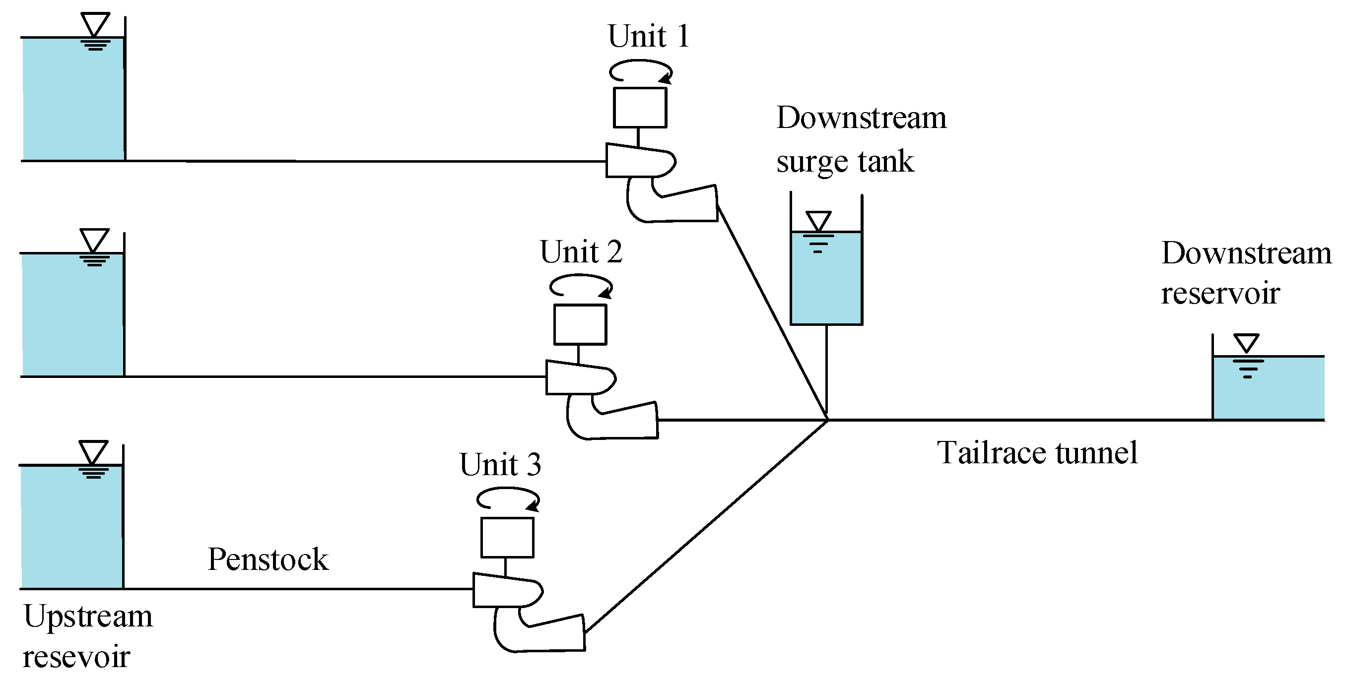
The schematic diagram of a three-unit hydropower system with a common tailrace tunnel and tailrace surge tank is shown in
Figure 1. To facilitate theoretical and simulation analysis, mathematical models of the penstock, surge tank, tailrace tunnel, governor, and hydro-turbine are developed based on operational principles and physical laws. These subsystems are coupled to establish an integrated model of the three-unit system comprising the shared tailrace tunnel and tailrace surge tank. The detailed modeling procedure is as follows.
Under the assumption of rigid water hammer, the dynamic equation of the penstock derived from Newton’s Second Law of Motion can be expressed as [
28]
where
and
denote the relative values of the flow and head of the
i-th unit, respectively;
represents the relative value of the surge tank water level;
and
denote the water inertia constant and head loss coefficient of the penstock for the
i-th unit, respectively;
denotes the deviation from the initial value.
Defining the direction of flow into the surge tank as positive, the equation of the surge tank can be expressed as [
29]:
where
denotes the relative value of flow in the tailrace tunnel;
represents the time constant of the surge tank.
The dynamic equation of the tailrace tunnel derived from Newton’s Second Law of Motion can also be expressed as:
where
and
represent the water inertia constant and head loss coefficient of the tailrace tunnel, respectively.
The characteristics of the hydro-turbine are described using the simplified nonlinear analytical model [
30]. The relationship between the head and flow of the hydro-turbine is as follows:
where
and
denote the proportional coefficient of the hydro-turbine and the relative value of the guide vane opening for the
i-th unit, respectively.
The output power of the hydro-turbine can be expressed as:
where
and
denote the relative values of the hydro-turbine output power and the hydro-turbine no-load flow, respectively.
By linearizing Equations (4) and (5), the linear model for the hydro-turbine is obtained as follows:
where
and
denote the initial values of the hydro-turbine head and guide vane opening for the
i-th unit, respectively.
Under grid-connected operation, the turbine governor operates in power control mode, with its input signal being the power deviation (i.e.,
). The governor typically employs PI regulation in this mode [
31]. Introducing an intermediate variable
, the governing controller equations can be expressed as follows:
where
denotes the relative value of the input power deviation for the
i-th unit;
denotes the relative value of the output control signal deviation for the
i-th unit;
and
denote the proportional and integral coefficients of the governor for the
i-th unit, respectively.
The servo system can be represented by a first-order inertial element as follows [
31]:
where
denotes the time constant of the servo system for the governor of the
i-th unit.
Under the assumption of constant rotor speed during grid-connected operation (large grid integration), the generator model is neglected in this study. By integrating Equations (1)–(8), the linear state-space equations for the three-unit system with common tailrace tunnel and tailrace surge tank shown in
Figure 1 are derived as follows:
where
denotes the system state variable vector under the power control mode;
denotes the system state matrix under the power control mode; its expression is given in
Appendix A.
3. Stability Analysis of Three-Unit Shared Tailwater System
According to Lyapunov stability theory, the small-signal stability of the system under power control mode can be determined by analyzing the eigenvalues of the system state matrix
. The eigenvalues of the system are expressed as follows:
where
represents the
-th eigenvalue of the system;
denotes the real part of the
-th eigenvalue, reflecting the damping characteristics of oscillations;
indicates the imaginary part of the
-th eigenvalue, corresponding to the oscillation frequency.
The model of the three-unit system shared tailrace tunnel and tailrace surge tank is developed on the Matlab/Simulink simulation platform (Matlab R2021a) to conduct stability studies. System parameters for the three-unit system are as follows [
26]: hydro-turbine rated flow
; hydro-turbine rated head
; water inertia constant of penstock
,
,
; head loss coefficient of penstock
,
,
; time constant of surge tank
; water inertia constant of tailrace tunnel
; head loss coefficient of tailrace tunnel
; hydro-turbine coefficient
,
,
; hydro-turbine no-load flow
pu,
pu,
pu; time constant of the servo system
,
,
; control parameters
,
,
,
,
,
; hydro-turbine output power
pu.
By substituting the aforementioned parameters into the system model, stability studies of the three-unit system shared tailrace tunnel and tailrace surge tank are conducted. In accordance with Lyapunov linear stability theory, the system eigenvalues are calculated, and the dominant state variables affecting each eigenvalue are identified based on participation factors. The results are presented in
Table 1.
As shown in
Table 1, there are three decay modes and four oscillation modes in the three-unit system. These modes all possess negative real parts; hence, the system is stable under small disturbances. The oscillation frequencies of these oscillation modes are all less than 0.1 Hz. This study primarily focuses on the oscillation characteristics of the system. According to the results of the participation factor analysis, the control parameters of Unit 1 influence system oscillation stability by mainly affecting eigenvalues
and
. The control parameters of Unit 2 influence system oscillation stability by mainly affecting eigenvalues
and
. The control parameters of Unit 3 influence system oscillation stability by mainly affecting eigenvalues
and
.
To analyze the impact of governor control parameters on system stability, the stable domains for the proportional and integral control parameters of the three-unit system governors are calculated and shown in
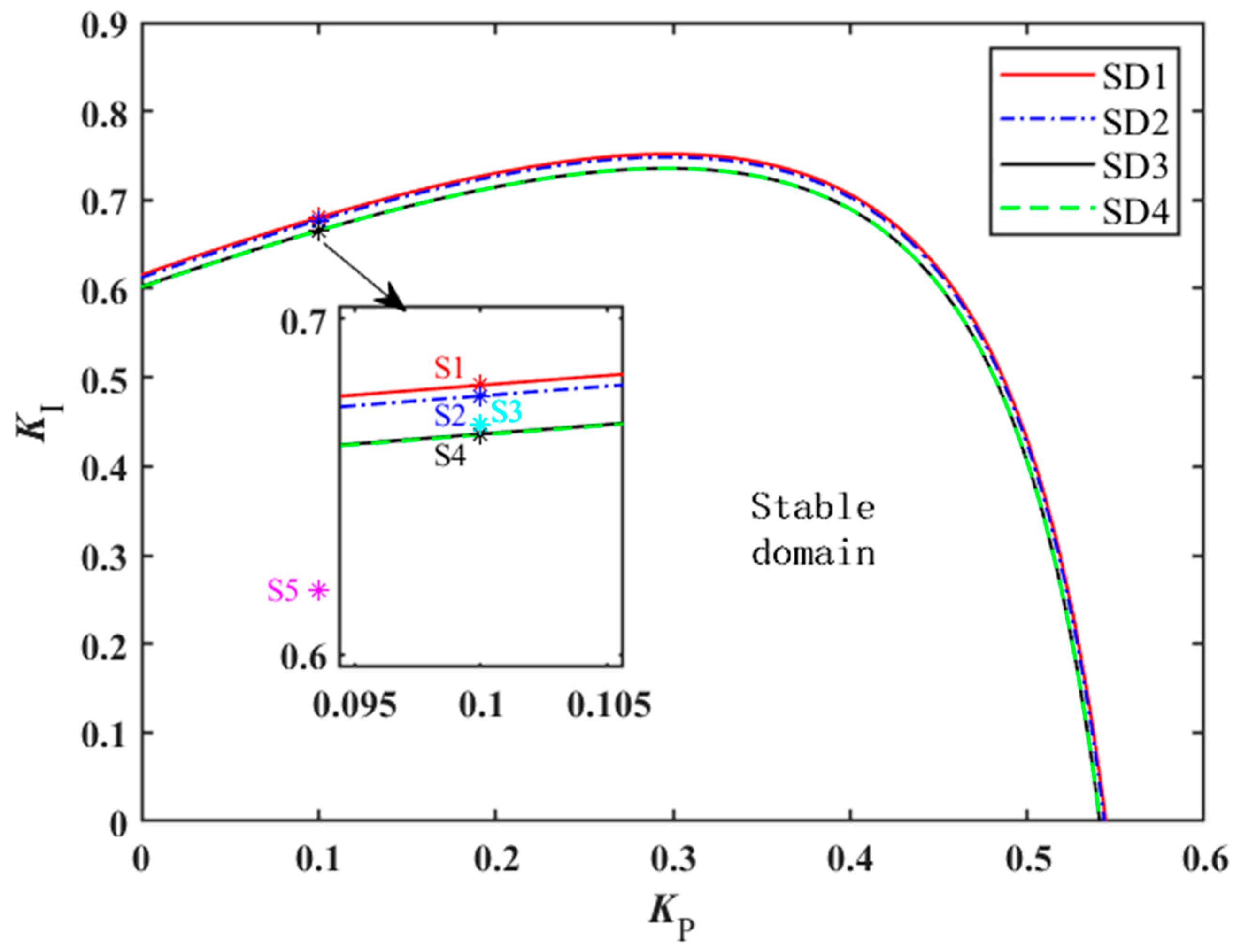
Figure 2. When the governor control parameters of the three units shared tailrace tunnel system in
Figure 1 are set independently, each unit will exhibit distinct stable domains of the governor control parameters. The stable domains for Unit 1, Unit 2, and Unit 3 are denoted as SD1, SD2, and SD3, respectively. When the governor control parameters of the three units shared tailrace tunnel system in
Figure 1 are set consistently, the stability of all three units depends on a single set of governor control parameters. The corresponding stable domain of three-unit system is denoted as SD4.
As illustrated in
Figure 2, the stability regions for the governor control parameters of Unit 1, Unit 2, and Unit 3 decrease sequentially. According to the system parameter settings, the water inertia constant of the penstock s for Units 1, 2, and 3 are sequentially increased, while all other parameters are set identically. This indicates that the larger the water inertia constant of the penstock, the poorer the stability of the unit. Additionally, when the governor control parameters for Units 1, 2 and 3 are consistent, the stable domain SD4 of the three-unit system governor control parameters is essentially identical to the previously mentioned stable domain SD3 for Unit 3 governor control parameters.
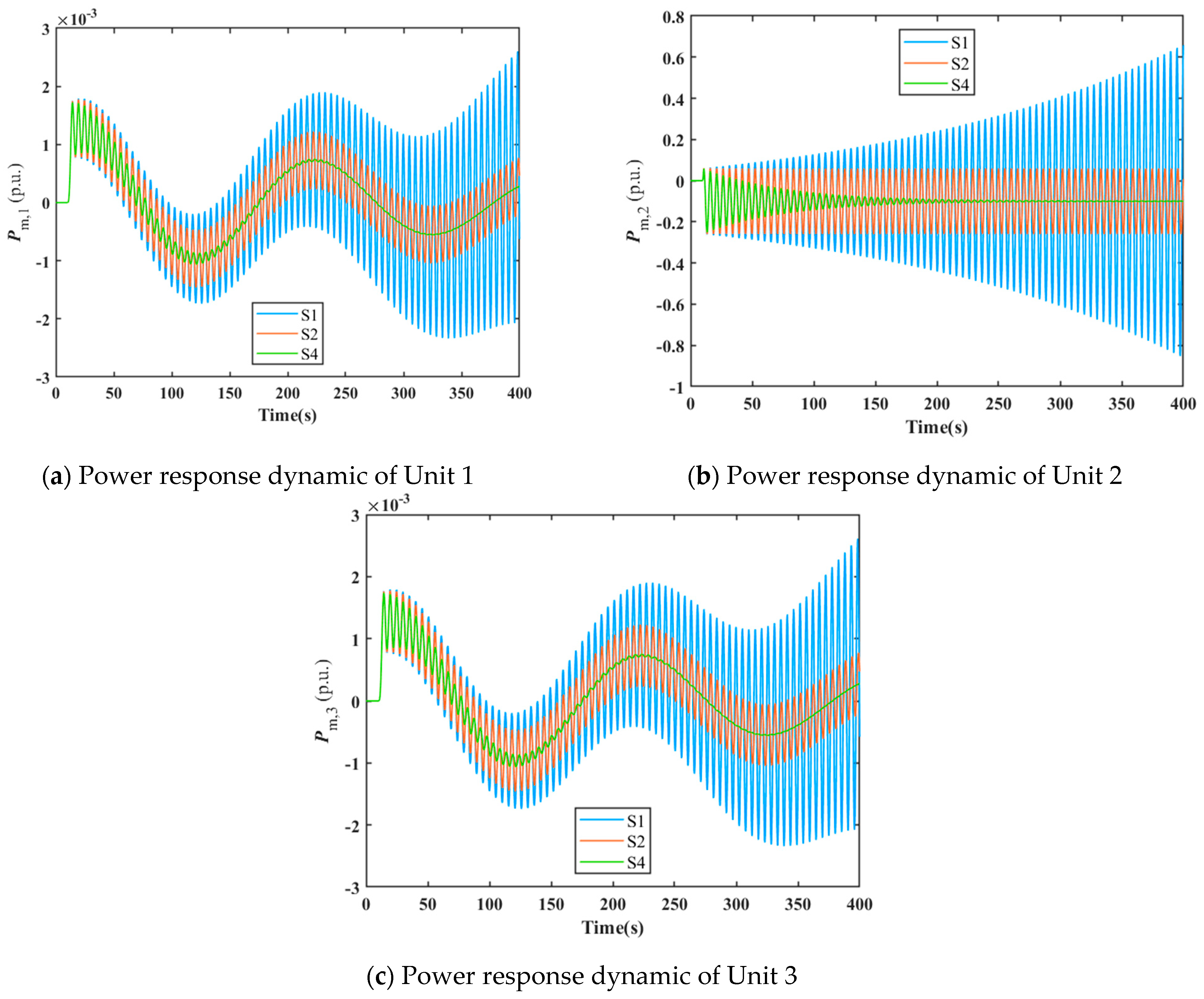
To validate the aforementioned stability domain results, the dynamic response of three-unit shared tailrace tunnel systems is solved and analyzed under different governor control parameter settings. When the governor control parameters of the three units are mutually independent, three state points S1 (0.1, 0.680), S2 (0.1, 0.677), and S4 (0.1, 0.665) shown in
Figure 2 are selected for dynamic response simulation of the three-unit shared tailwater tunnel system. Points S1, S2, and S4 lie on the boundaries of the stable domains for Units 1, 2, and 3, respectively. The corresponding control parameter values for these three points are substituted into the governor model of Unit 2. Dynamic simulations of the three-unit shared tailrace tunnel system are then conducted under a −0.1 pu disturbance to the power setpoint of Unit 2. The power response processes for Units 1, 2, and 3 are illustrated in
Figure 3.
As shown in
Figure 3, under a power step disturbance of −0.1 pu applied to Unit 2, the time-domain power responses exhibit divergent behavior at state point S1 outside the stable domain. At state point S2 on the boundary of the stability domain, the power response displays constant-amplitude oscillation. Conversely, at state point S4 within the stable domain, the power response dynamic converges. The above time-domain simulation results further validate the correctness of the parameter stable domain result.
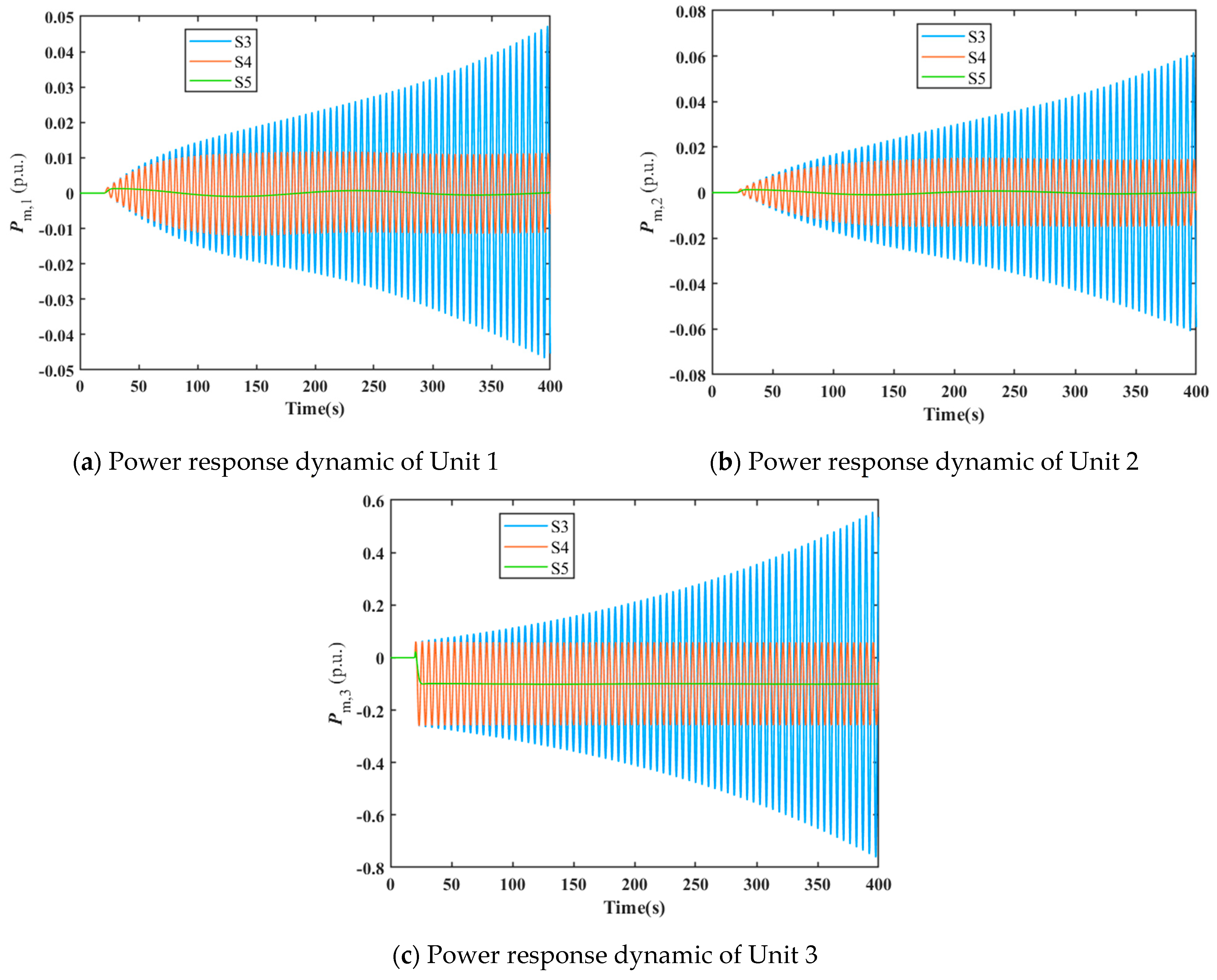
When the governor control parameters of all three units are maintained consistent, three state points S3 (0.1, 0.668), S4 (0.1, 0.665) and S5 (0.1, 0.260) shown in
Figure 2 are selected for dynamic response simulation of the three-unit shared tailrace tunnel system. Specifically, S3, S4, and S5 are situated externally, at the boundary, and internally within the three-unit system’s stable domain, respectively. The control parameter values corresponding to these three state points are substituted into the three-unit system governor model to conduct dynamic simulations of the three-unit shared tailrace tunnel system under a −0.1 pu disturbance applied to the power setpoint of Unit 3. The resulting power response processes for Units 1, 2, and 3 are illustrated in
Figure 4.
As shown in
Figure 4, under a power step disturbance of −0.1 pu applied to Unit 3, the time-domain power responses exhibit divergent behavior at state point S3 outside the stable domain. At state point S4 on the boundary of the stable domain, the time-domain power response exhibits constant-amplitude oscillation. Conversely, at state point S5 within the stable domain, the time-domain power response converges. The aforementioned time-domain simulation results also validate the correctness of the parameter stable domain result.
Furthermore, as demonstrated by the results in
Figure 3 and
Figure 4, despite applying power step disturbances only to Units 2 and 3, respectively, the shared tailrace tunnel system still induces similar minor power oscillations in other units operating within the stable domain. This fully reflects the internal coupling characteristics of the system.
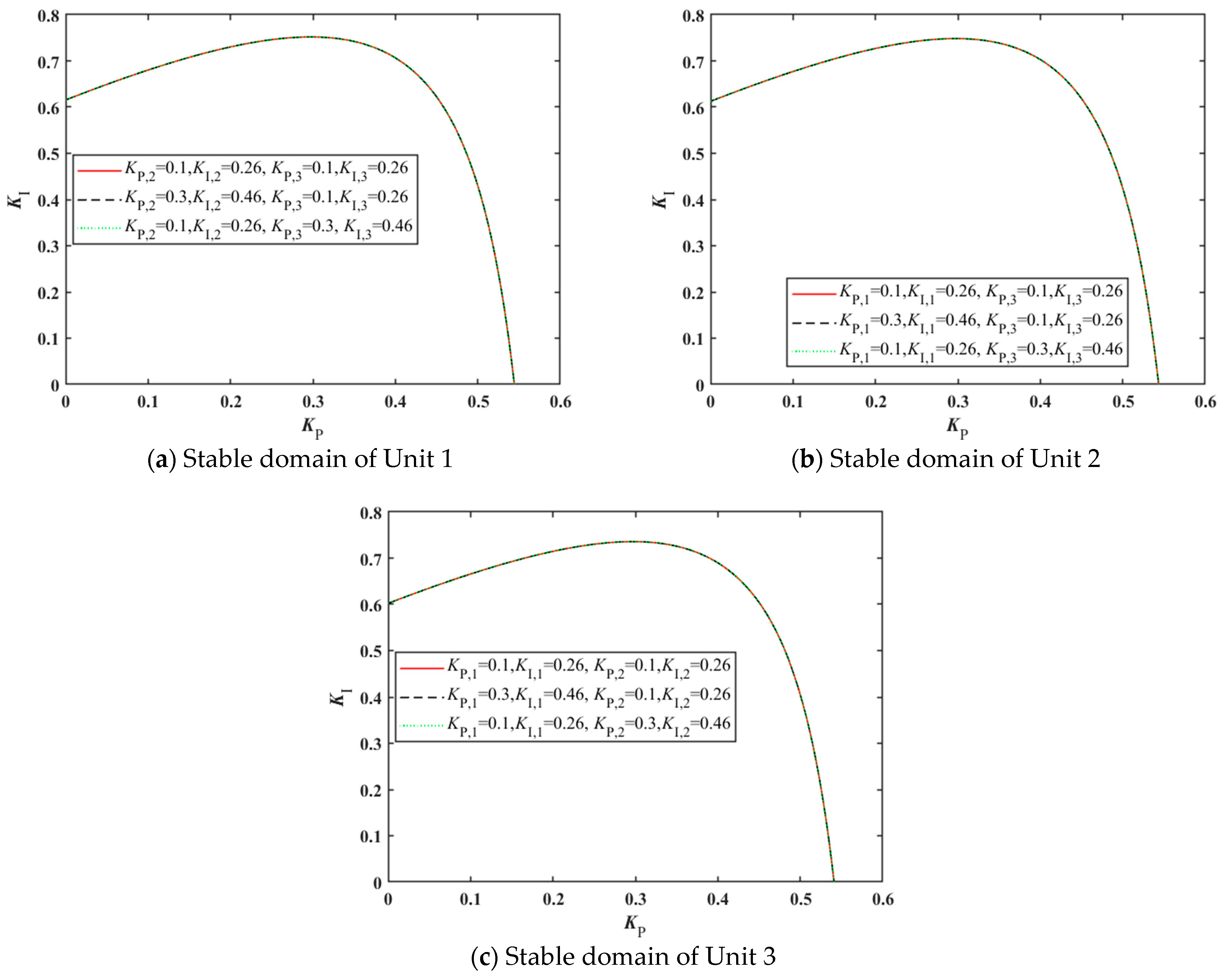
To clarify the impact of control parameters of each unit within the three-unit common tailrace tunnel system on the stability of other units, the control variates method is employed for investigation. The effects of variations in the respective control parameters of Units 1, 2, and 3 on the stable domains of other units are analyzed, with results presented in
Figure 5.
As can be seen from
Figure 5a, variations in the control parameters
and
of Unit 2, as well as variations in the control parameters
and
of Unit 3, exert negligible influence on the stable domain of Unit 1; As shown in
Figure 5b, variations in control parameters
and
of Unit 1, as well as variations in control parameters
and
of Unit 3, exert negligible influence on the stable domain of Unit 2. As depicted in
Figure 5c, variations in control parameters
and
of Unit 1, as well as variations in control parameters
and
of Unit 2, exert negligible influence on the stable domain of Unit 3.
Based on the above results, independent adjustments of the governor control parameters for individual units in the three-unit shared tailrace tunnel system demonstrate negligible effects on the stable domains of other units. It follows that when the governor control parameters of all three units are maintained consistently, the stable domain of the three-unit system is essentially determined by Unit 3, which possesses the smallest stable domain. This corresponds to the results in
Figure 2, where stable domains SD4 and SD3 are largely coincident. The aforementioned conclusions indicate that within the three-unit shared tailrace tunnel system, the control parameters of each unit primarily influence the overall system stability by altering their own stability characteristics.
4. The Impact of Unit Power Output on System Stability
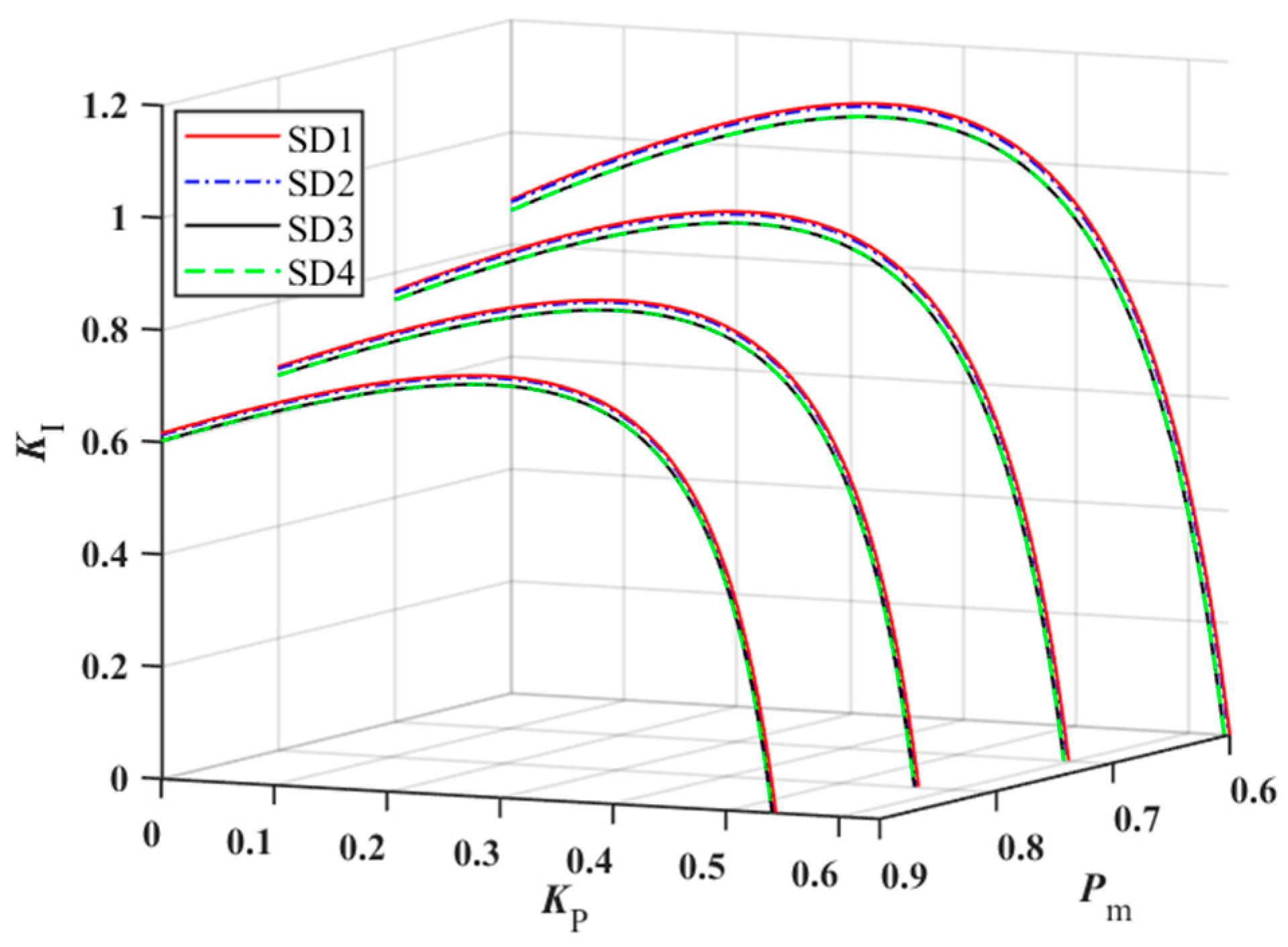
Hydropower units possess flexible regulation capabilities and can ensure the secure and stable operation of the grid by participating in peak shaving. During the peak shaving process of hydropower units, changes in unit power output are important factors affecting system operational characteristics. To investigate the impact of varying unit power levels on system stability, the stable domains for each unit under four power conditions, i.e., 0.6 pu, 0.7 pu, 0.8 pu, and 0.9 pu, are plotted for Units 1, 2, and 3 operating at identical power levels, as illustrated in
Figure 6. The symbols SD1, SD2, SD3, and SD4 retain their previously defined meanings.
As shown in
Figure 6, the stable domains of Units 1, 2, and 3 all decrease with increasing power output, and the relative sizes of the stable domains for the three units remain unchanged. Simultaneously, when the governor control parameters for all three units are kept consistent, the stable domain of the three-unit system also decreases with increasing power output. Moreover, at different power output levels, this stable domain is essentially identical to that of Unit 3, further validating the conclusions drawn in
Section 3. The aforementioned results indicate that increased power across all three units exerts a detrimental effect upon their respective stability.
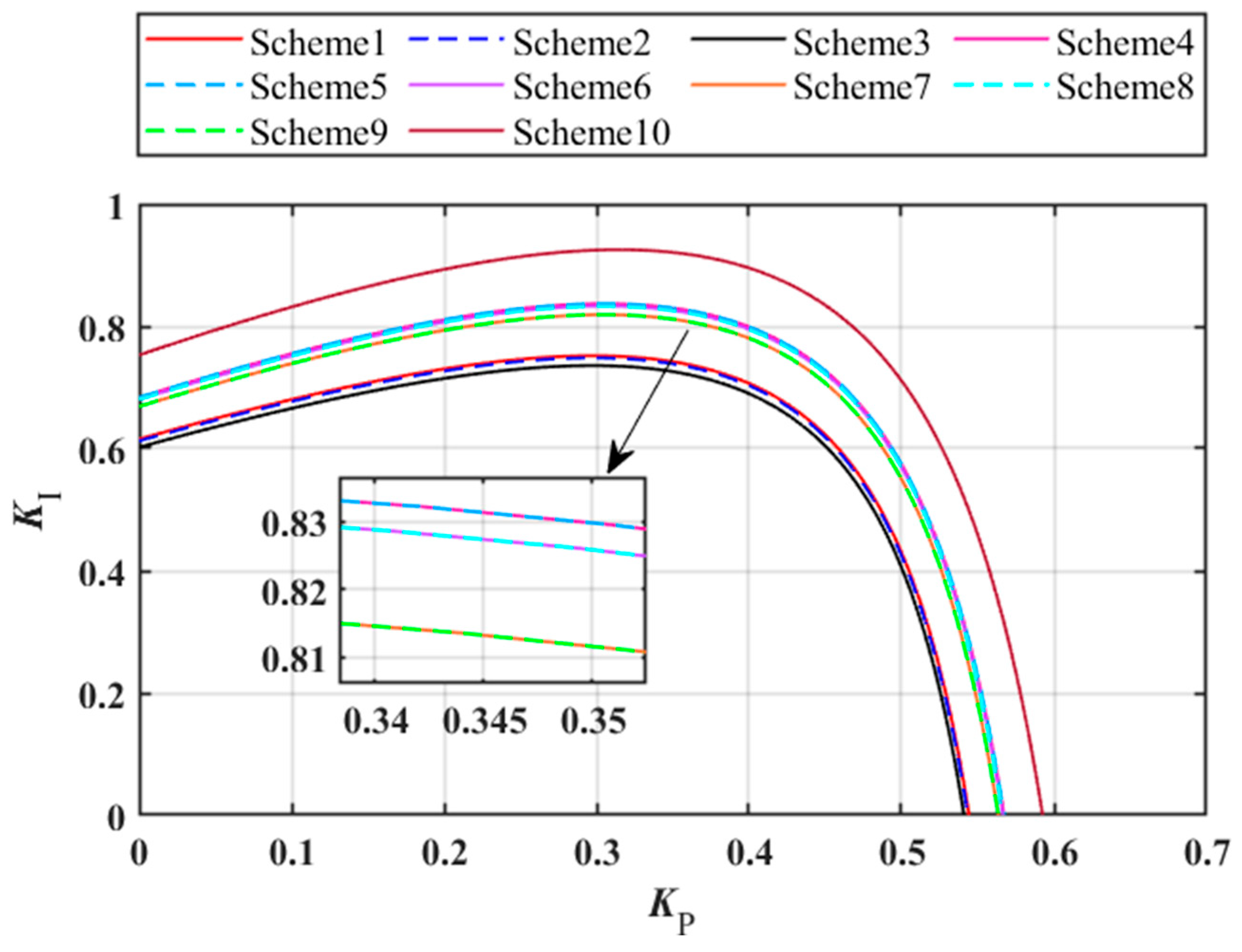
Furthermore, the impact of different power allocation schemes on the stability of the three-unit shared tailrace tunnel system is investigated. For convenience of analysis, the minimum stable domain ensuring stable parameters for all units is considered, i.e., the stable domain of the three-unit system when the governor control parameters of all three units remain consistent. When the initial powers of Units 1, 2, and 3 are all set to 0.6 pu, there are 10 possible allocation methods for adding 0.3 pu of power to the entire three-unit system, as shown in
Table 2. The stable domains of the three-unit system under these ten different power allocation schemes are depicted in
Figure 7.
As shown in
Figure 7, the three-unit system stable domain is smallest when Scheme 3 allocates 0.3 pu power to Unit 3. The stable domains for the three-unit system under Schemes 1 and 2, which allocate 0.3 pu power to Units 1 and 2, respectively, are slightly larger than those under Scheme 3. Schemes 4 and 5 both allocate 0.2 pu power to Unit 1, yielding essentially identical three-unit system stable domains. Similarly, Schemes 6 and 8, which allocate 0.2 pu power to Unit 2, produce nearly identical stable domains. Likewise, Schemes 7 and 9, allocating 0.2 pu power to Unit 3, result in substantially comparable stable domains. The stable domains of the three-unit system corresponding to the above three sets of schemes decrease sequentially but remain larger than those of the first three schemes. Scheme 10, which evenly distributes 0.3 pu power among Units 1, 2, and 3, yields the largest stable domain for the three-unit system. This demonstrates that when increasing power in a three-unit shared tailrace tunnel system, distributing power evenly among units is more conducive to stable system operation.
5. Discussion
The mathematical model and stability analysis results are discussed in this section. This study extends the single-machine single-tunnel system to a multi-machine shared-tunnel scenario, establishing a model that essentially represents an extension and optimization of the IEEE hydro-generator unit model. Although this model exhibits limited accuracy compared to [
17], its theoretical foundation remains consistent, thereby facilitating the analysis of hydraulic coupling characteristics within multi-machine systems. Previous studies have examined the stability characteristics of multi-unit hydroelectric systems, but few have considered them from the perspective of coupling effects and power allocation. This study establishes that system stability arises from the combined effects of ‘single-machine stability’ and ‘coupled disturbances’, with single-machine stability forming the foundation. It further reveals that the influence of multi-machine governor control parameters on the stability domain exhibits weak coupling, facilitating engineering tuning. Moreover, it clarifies that uniform power distribution constitutes the optimal operating strategy for maintaining stability in multi-machine systems.
The limitations of this paper are discussed as follows:
The paper employs a pipeline model based on rigid water hammer theory, which neglects complex hydraulic phenomena. Consequently, its dynamic description of the shared tailrace tunnel may be overly idealized. The study assumes that the three units are identical or share consistent characteristics. In practice, the dynamic properties of turbines within the system exhibit variations, potentially necessitating a revision of the conclusion regarding ‘optimal uniform power distribution’.
The model assumes an infinitely large grid, whereas in reality, hydroelectric power stations are connected to finite grids. The grid’s strength, load characteristics, and interactions with other generators significantly influence the system’s oscillation modes and damping. Future work must account for grid interactions: extending the model to scenarios involving grid connections to investigate the mutual influence between power system oscillations and hydraulic system oscillations.
Moreover, it is crucial to conduct engineering validation of the model by collecting operational data from actual power stations for calibrating and verifying the established mathematical model, thereby ensuring the model accurately reflects the dynamic characteristics of the real system.
