Abstract
Deep coal seams have low permeability and poor wettability, making gas extraction difficult. This study presents a zero-energy consumption pulsating water hammer fracturing technique that uses the gravitational potential energy of high-elevation water and the pulsating pressure waves from the water hammer effect to induce fatigue damage in coal, creating an interconnected network of cracks. The research included experiments on water hammer pressure waves, multi-physics field coupling simulations at different flow rates, and discrete element simulations to analyze the fracture behavior of underwater hammer pressure. Results showed that initial flow velocity impacts the water hammer pressure’s intensity, range, and duration. Pressure shock waves propagate as expansion and compression waves, with peaks rising from 4.99 to 19.91 MPa within a 2–12 m/s flow rate range. Water hammer pressure reduced fracture initiation pressure by 23% compared to static pressure loading and increased fracture numbers by 13.4%. With pressure amplitudes between 2–18 MPa, fractures tripled, and the damaged area grew from 2.2 to 11%. A variable frequency combination loading strategy, starting with low frequency and then high frequency, was more effective for fracture propagation. This study offers a theoretical foundation for applying this technology to enhance coal seam permeability and gas pumping efficiency.
1. Introduction
Abundant reserves of coal resources and continuous high demand have led to an annual deepening of coal mining in China by 10–25 m. As the mining depth increases, the ground stress, internal gas pressure, and gas emission volume of the coal seam all rise continuously, making gas disasters more complex and dangerous [,,,]. These coal seams typically exhibit high pressure, low permeability, micro-pores, and strong adsorption capacity [,]. Therefore, improving the permeability of high-gas and low-permeability coal seams is key to enhancing gas extraction efficiency and ensuring the safety of coal mine production [,,,].
Many scholars have proposed a variety of hydraulic fracturing techniques to address coal seam permeability enhancement and production increase, including hydraulic fracturing, hydraulic slotting, and hydraulic jet fracturing [,,,]. Due to the differences in the development of primary and secondary fracture systems in coal bodies, conventional hydraulic fracturing cannot achieve uniform coal body fracturing and thus fails to reach the expected permeability enhancement effect. Some scholars have proposed pulsed hydraulic fracturing permeability enhancement technology, widely applied in shallow coal seams, to address this issue. For instance, Chao et al. established a rock fracture damage degradation model and obtained the corresponding degradation curve through strength degradation experiments under different pulse pressures []. Ni et al. studied the influence of geological structures on pulsed hydraulic fracturing and concluded that natural pressure relief zones in faults harm the pulse pressure of pulse hydraulic fracturing (PHF) []. Xu et al. explored the impact of long-period pulse loading on coal body damage through experiments and nuclear magnetic resonance technology []. Given this, many scholars have innovatively proposed water hammer pulsed fracturing technology. Li et al. used a variable frequency method to enhance the fatigue damage effect, which is beneficial for crack propagation and connection under pulse pressure []. Ramos et al. developed an advanced method for characterizing hydraulic fracturing through pulse test analysis and extended it to more complex multi-stage fracture cases. This method achieved good consistency regarding fracture direction, height, and length []. Xie et al. studied the PHF impact on coal pore structure changes []. López-Comino et al. proposed the concept of fatigue hydraulic fracturing, combining cyclic progressive hydraulic fracturing with pulsating hydraulic fracturing [,]. Ding et al. proposed a novel hydraulic high-pressure pulse generator using a combination of sleeves and rotating valve cores, with an intensifier piston applied to amplify the output pressure []. Xi et al. validated the developed numerical model through experimental results of rock PHF and proposed a new loading strategy []. Gao et al. proposed a new self-excited pulse oscillator and concluded that the fracture specimens under pulse loading exhibited a more complex crack propagation pattern []. Wang et al. investigated the physical mechanisms of water layers on the morphological evolution of transient pulse high-velocity water jets []. Li et al. developed a novel frequency model that reveals optimal pulse frequencies significantly elevate peak pressure at endpoints, depending on pipeline or fracture length and wave velocity []. Hou et al. used a transient flow model to describe the physical process of pressure wave propagation caused by PHF, fully discussing the influence of related factors on the behavior of pressure wave propagation []. Zhu et al. established a fluid–solid coupling hydraulic fracturing simulation model considering fatigue damage [,]. He et al. proposed an advanced step rectangular pulsating hydraulic fracturing technique. Compared to conventional hydraulic fracturing, this technique can extend the unsteady propagation time, increase pressure, and create a more complex pressure distribution [,]. Chang et al. introduced the wavelet transform to analyze the characteristics of pressure pulsation and energy fluctuation []. Yu et al. studied the impact of PHF on coalbed methane production in laboratory and field settings. The results showed that prolonged hydraulic pulse pressure leads to a linear decrease in initiation pressure, providing more flow channels and enhancing permeability [].
Water hammer pulsed fracturing can have a more positive effect than conventional hydraulic fracturing, but currently, there are few studies and applications related to using water hammer effects to generate pressure waves for coal fracturing. There is little research on the generation and propagation laws of pressure under water hammer effects, and the fracture expansion mechanism under water hammer action is unclear. Based on this, this paper first constructs a water hammer pressure wave measurement experiment system to conduct water hammer generation experiments under different initial fluid states and analyzes the morphological characteristics of water hammer pressure waves. Secondly, it analyzes the water hammer pressure propagation law based on the transient flow model. It combines the water hammer motion equation and continuity equation to obtain a theoretical model for the propagation of water hammer pressure waves in fractures, thereby establishing a corresponding numerical model to simulate the impact of changes in flow velocity on its water hammer impact characteristics, explore the propagation laws of water hammer pressure, and verify them with experiments. Finally, based on the PFC simulation software PFC 5.0, a model is established to simulate and analyze the initiation and expansion laws of coal fractures under water hammer pressure wave loading conditions, explore the role of water hammer parameters (pressure amplitude and frequency) in the fracture evolution process and their combination laws, further elucidate the different fracturing effects of combinations of pressure amplitude and frequency on coal seams, these research results can provide valuable insights for engineering practices such as coal seam fracturing and gas extraction.
2. Materials and Methods
2.1. Experiment on the Water Hammer Effect
The water hammer effect occurs in a similar experimental system platform, as shown in Figure 1.
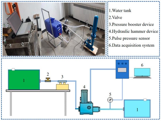
Figure 1.
Experimental system platform similar to the occurrence of the water hammer effect.
A water hammer generation device is used to trigger the fluid to produce a water hammer effect, truly displaying the occurrence of the water hammer effect, conducting experiments on the water hammer effect produced by fluids under different initial flow rates, and exploring the pulsed water hammer pressure generated by the water hammer effect under different conditions and its propagation rules. The constructed water hammer effect generation similar experimental system mainly includes a water hammer effect generation device, a water supply tank, supporting water delivery pipelines, an initial pressurization device, a pulse pressure sensor, and a data acquisition system.
Experimental Plan and Procedures
By setting different initial flow rates to simulate the velocity generated by the water’s weight under different drops, experiments on the occurrence of the water hammer effect under different inlet pressures are conducted to simulate the zero-energy consumption pulsed water hammer fracturing effect in actual working conditions. The experimental setup includes a 40-L water storage container, a CHM2-6 type variable frequency pressurizing pump, a no-drip water hammer pump (which can generate a higher head and greater pressure by inducing a water hammer effect), and a DY2000 type high-precision digital pressure sensor (with a range of 0–25 MPa and a system accuracy of 0.01%). Since flow rate and pressure influence each other and there is a positive correlation between changes in flow rate and pressure [], it is necessary to adjust appropriate flow rates and pressures during the experiment. A pressure sensor is used at the outlet to measure and record the peak values of the pulse pressure waves. The specific experimental plan is as follows:
The variable selected in this experiment is to control the size of the inlet pressure of the water hammer pump, that is, to apply an initial pressure to the water flow through the pressurization device, replacing the driving pressure generated by the mine drop during the process of water flowing from the ground reservoir to the water hammer pump in actual working conditions. The experimental plan is as follows:
- Experiment preparation: First, check the condition of each piece of equipment and its connection to ensure the safety of the experiment. Then, connect the power supply and debug the equipment to ensure normal operation;
- Turn on the pulse pressure detection system, set the parameters of the pulse pressure sensor and the collection zero point, perform calibration, and set the file to be automatically saved to the computer;
- Open the tank outlet valve, start the pressurization device, set the water flow velocity to 0.6 m/s through the digital control panel, and wait until the operation stabilizes; then, the water flow is driven into the water hammer pump while data collection begins. At the end of the experiment, first, turn off the pressurization device and the tank outlet valve, then stop data collection, discharge the tailwater, and complete one set of experiments;
- Adjust the pressurization device’s control panel, adjust the flow velocity to 0.8, 1.0, and 1.2 m/s, repeat the experimental steps (3), and complete the experiments for various conditions.
2.2. Simulation of Water Hammer Pressure Waves
The water hammer effect refers to the phenomenon where a stable flowing fluid experiences a change in flow rate due to external disturbances, leading to a rapid fluctuation in fluid pressure (usually presented as pressure waves). The transient pressure generated is known as the water hammer pressure. Water hammer is often considered a hazardous factor in water supply pipeline systems. Still, some scholars have utilized this principle for controllable operations, turning it from a disadvantage to an advantage in coal fracturing.
If water hammer technology is applied in coal seam permeability enhancement, a water hammer generation device must be introduced into the conventional coal seam hydraulic fracturing system. The high drop caused by the depth of the coal mine can provide driving power for the water hammer device, thus forming a periodic pulsating pressure source. By leveraging the pressure waves generated by each water hammer transient impact in the coal seam fractures and using water flow as the medium of propagation, the internal pores of the coal seam are cracked and connected, widening the permeation channels and creating more fractures, thereby improving the permeability of the coal seam. The zero-energy consumption pulsed water hammer fracturing technology studied here uses the high drop as the original driving force to stimulate the water hammer effect to generate pulsating pressure waves, which are then conducted through a medium to the coal body to achieve the purpose of fracturing.
The mathematical model of the water hammer is based on the principles of continuity and fluid flow dynamics. Starting from the physical essence of the water hammer phenomenon, by analyzing the changes in water hammer pressure and wave velocity when the fluid motion state changes instantaneously, the basic differential equation for unsteady flow used for water hammer analysis can be derived. Closing a valve in the water supply pipeline will change the flow velocity, thereby increasing the water pressure. This pressure increase, known as the water hammer pressure, can be derived using the momentum theorem.
where ρ is the fluid density, kg/m3; a is the velocity of water hammer wave propagation, m/s; P is the change in water hammer pressure, MPa; V is the change in flow velocity, m/s.
ΔP = aρΔV,
The calculation formula for the water hammer wave velocity, a, can be derived based on the principle of mass conservation:
where S is the cross-sectional area of the fracture, m2.
a = 1/√ρ(1/S dS/dP + 1/ρ dρ/dP),
The water hammer effect is an unsteady flow phenomenon in which variation follows the motion laws described by the basic differential equations of one-dimensional unsteady flow. There are 7 fundamental differential equations for the water hammer, including continuity and motion equations. The pressure and flow rate changes at each node in the straight fracture system can be determined by solving these equations. If a horizontal straight fracture segment is taken as the research object, then the motion equation takes the following form:
where h is the fracture width, m; λ is the axial resistance coefficient, related to the shape and roughness of the fracture.
g ∂P/∂l + ∂V/∂t + V ∂V/∂l + λV |V|/2 h = 0,
At the same time, according to the principle of mass conservation, the general expression for the continuity equation is as follows:
∂/∂l (ρSV) + ∂/∂t(ρS) = 0.
Under the water hammer effect, assuming that the fluid and fracture wall changes are linear elastic deformations, the fracture’s cross-sectional area, fluid density, flow velocity, and pressure are all functions of time and distance. This yields the following:
l/S dS/dt + 1/ρ ∂ρ/dt + ∂V/∂l = 0.
Substituting the water hammer wave velocity into the above equation yields the water hammer continuity equation:
1/ρa2 dp/dt + ∂V/∂l = 0.
The transient flow model, also known as the unsteady flow model, is mainly used for analyzing and predicting temporary fluid changes within pipes or channels, especially rapid pressure fluctuations caused by valve operations, pump start–stops, or other sudden events. This model can capture the changes in fluid velocity, pressure, and flow rate over time and is a key model for studying water hammer effects.
Relevant scholars studying the propagation characteristics of pulse pressure waves proposed using the transient flow model to explore these features []:
where P is the fluid pressure, MPa; V is the fluid flow velocity, m/s; l is the model length, m; c is the pulse pressure wave velocity, m/s; g is gravitational acceleration, m/s2; t is time, s; R(V) is the pressure propagation velocity resistance parameter, which is also known as viscous drag.
∂p/∂t + V ∂p/∂l + c2/g ∂V/∂l = 0,
∂V/∂t + V ∂V/∂l + ∂p/∂l +R(V)V = 0,
To study the propagation of water hammer pressure, based on the transient flow model, the propagation model is simplified to a straight model, considering the transient characteristics of pressure waves:
∂p/∂t >> ∂p/∂l,
∂V/∂t >> ∂V/∂l.
Ignoring the resistance term between parallel plates, the transient flow model is simplified to obtain the transient flow equation set for pulsed water pressure propagation under ideal conditions:
∂p/∂l + l/g ∂V/∂t = 0,
∂p/∂t + c2/g ∂V/∂l = 0.
The general solution to the equation is as follows:
where is the initial pressure, MPa; is the initial flow velocity, m/s; and are the waveform functions for the forward and backward propagation of the pulse pressure wave, respectively. The above transient flow model shows that the body exhibits one-dimensional transient flow when a water hammer occurs. The propagation of pressure waves involves the mutual conversion between the kinetic energy and the pressure energy of water. The flow velocity has a significant impact on the characteristics of the water hammer shock, including its intensity, the range of areas where water hammer pressure is generated, and the duration of the water hammer pressure. Based on the above water hammer mathematical model, a multi-physics field simulation is used to establish a water hammer numerical model. This model’s main body is a pipeline section with one end as the inlet and the other as a valve. Pressure measurement points are set at various locations along the pipe. The initial condition is that the valve is open, and water flows steadily at a velocity and pressure. At times, the valve closes instantaneously, thereby initiating the water hammer. By setting different initial velocities as the input boundary conditions for the water hammer model, the water hammer pressure generated by the instantaneous valve closure during fluid flow under different initial conditions and the propagation process of the water hammer pressure are simulated. This allows for validation and further analysis of the experiment. The water hammer model parameters are listed in Table 1.
p − p0 = F(t − l/c) + f (t + l/c),
V − V0 = −g/c [F(t − l/c) + f (t + l/c)],

Table 1.
Water hammer model parameters.
2.3. Numerical Simulation of the Extension Law of Coal Fractures
Before conducting a discrete element fracturing simulation, the micromechanical parameters of the particle flow model were calibrated through uniaxial tests. After mesoscale parameter calibration, the simulation parameters used during the simulation process are listed in Table 2.
Table 2.
Basic mesoscopic parameters of the model.
To clarify the effect of water hammer pressure waves on the extension of coal seam fractures, a plane surrounding rock numerical model measuring 5 m × 5 m was established using discrete element simulation software PFC 5.0. A fracturing hole is set at the center of the numerical model, with the size of the fracturing hole specified as Φ100 mm. The numerical model is shown in Figure 2.
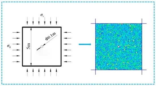
Figure 2.
Schematic of the numerical model.
The static initial boundary conditions of the model involve applying displacement constraints and static stress boundary conditions around the model. A static load of 5 MPa is applied to the model boundaries during the simulation. The model’s dynamic boundary condition at the fracturing hole is set as the shock wave generated by the water hammer effect. To study the influence of the water hammer shock waveform on the fracture extension pattern during cracking, the monitored shock waveform from the experiment is simplified to establish a pressure waveform that highlights the water hammer pressure fluctuation pattern. As shown in Figure 3, the shock wave pressure curve in the model is simplified into a rectangular waveform.
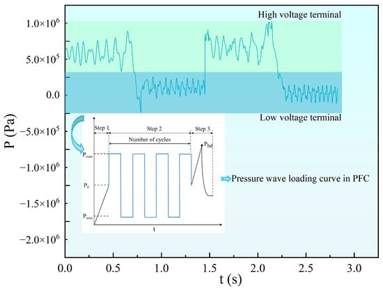
Figure 3.
Schematic of pressure loading waveforms.
Through discrete element simulation (DES), the evolution process of fractures in the coal body model under different loading conditions can be studied, allowing for a visual presentation of the complex fracturing process. The simulation analyzes the effectiveness of water hammer pulsation fracturing by comparing the fracture evolution characteristics under static pressure and water hammer action. Parameters such as the direction of crack initiation, initiation pressure, and the number of fractures are studied while also exploring the characteristics of crack initiation and propagation under different water hammer parameters.
3. Results and Discussion
3.1. Characteristics and Peak Patterns of Water Hammer Pressure Waves
This experiment only considers the pressure fluctuation at the outlet when a water hammer occurs. Data collection starts before the water hammer and ends after some time post-water hammer, with invalid data before and after the event being excluded. Only the pressure signal within one cycle is processed to obtain the pressure-time relationship.
Figure 4 shows the transient waveform, which shows the transient changes and propagation of pressure waves after the occurrence of a water hammer under different initial velocities. The fluctuation patterns are similar and transmitted in the form of pulse waves. The water hammer shock occurs instantaneously, with the pulse pressure surging, fluctuating, and decreasing over time. When collecting waveforms at a flow velocity of 0.6 m/s, the pressure wave during the water hammer event rises in a “trumpet” shape and decays to a stable state. This is due to the complex conditions of the actual environment, causing pressure waves to cancel each other out, thus decaying more quickly to equilibrium.
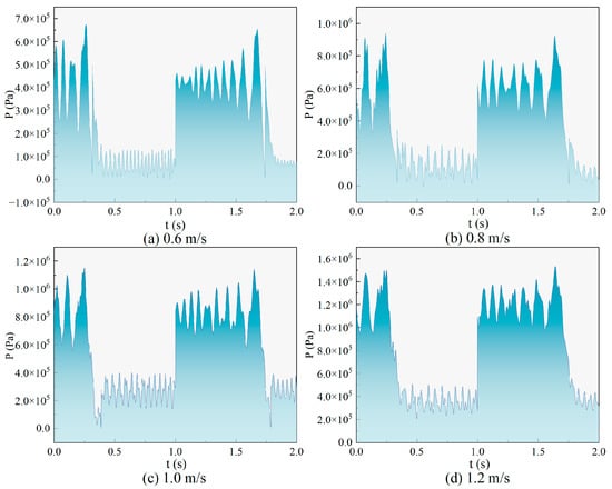
Figure 4.
Water hammer pressure fluctuation curves at different initial flow rates.
To quantitatively analyze the dynamic changes in water hammer pressure, the pulse pressure variation rate is used to characterize the non-uniformity of water hammer pressure. The pulse pressure variation rate, K, is a parameter used to describe the characteristics of pressure fluctuations, reflecting the non-uniformity of pressure peaks, troughs, and pulse pressures during dynamic changes. This parameter, specifically characterizes the amplitude of pressure changes, defined as the difference between the maximum pulse pressure P1 (i.e., the peak value of the pressure wave) and the minimum pulse pressure P0 (i.e., the trough value of the pressure wave), , relative to the average pulse pressure within one cycle.
As shown in Table 3 and Figure 5, the pulse pressure variation rate reveals the intensity and non-uniformity of pressure fluctuations and is an important indicator for assessing the characteristics of pressure fluctuations. The pulse pressure variation rates obtained from the four groups of experiments are 127, 127, 148, and 139%, respectively.
Table 3.
Pressure ranges for high- and low-pressure sections of water hammer in a single cycle.
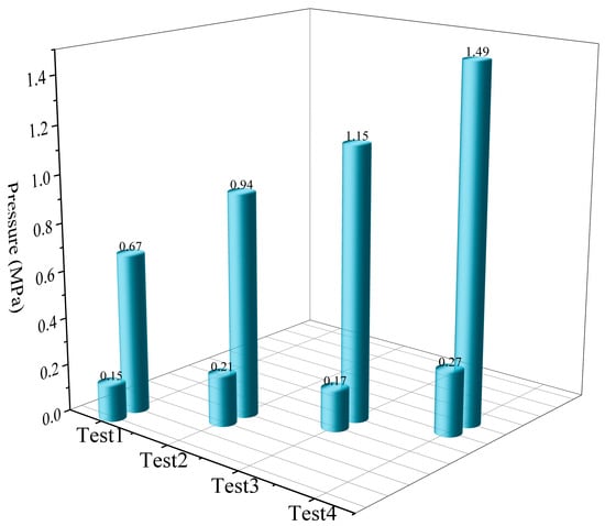
Figure 5.
Comparison of peak and trough values of water hammer pressure wave in different groups.
3.2. Analysis of Water Hammer Pressure Wave Simulation Propagation Patterns
Before conducting simulation studies, it is necessary to verify the reliability of numerical simulation results through mathematical model validation. In conjunction with water hammer experimental research, initial conditions of 0.6, 0.8, 1.0, and 1.2 m/s were selected to explore the water hammer pressure generated by the instantaneous closure of a valve under stable water flow conditions.
Figure 6 shows that, compared to the experimental data, the simulated water hammer pressure peaks are slightly higher. This is primarily because the simulation neglects the influence of frictional resistance on the propagation of water hammer pressure. However, the overall trends align well, indicating that the simulated mathematical model is feasible.
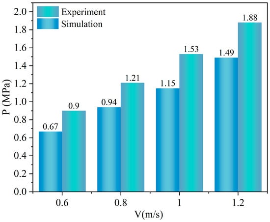
Figure 6.
Comparison of simulated and experimental results.
Figure 7 illustrates that the pulse water hammer pressure waveforms under different initial conditions exhibit a consistent pattern. However, the amplitudes of pressure fluctuations between the high- and low-pressure regions differ. As the fluid flow velocity increases, the peak pressure of the water hammer shock wave also rises. At an initial flow velocity of 6 m/s, the pressure can jump to 8.38–11.68 MPa; at 8 m/s, it can reach 10.62–13.89 MPa. It is observed that a secondary pressure rise occurs at the end of each water hammer shock wave impact on the pipeline, with the secondary pressure increase occurring in a brief, alternating manner. This phenomenon is attributed to the sudden obstruction during fluid motion, which triggers an instantaneous water hammer effect, driven by inertia and the superposition of reflected pressure waves.
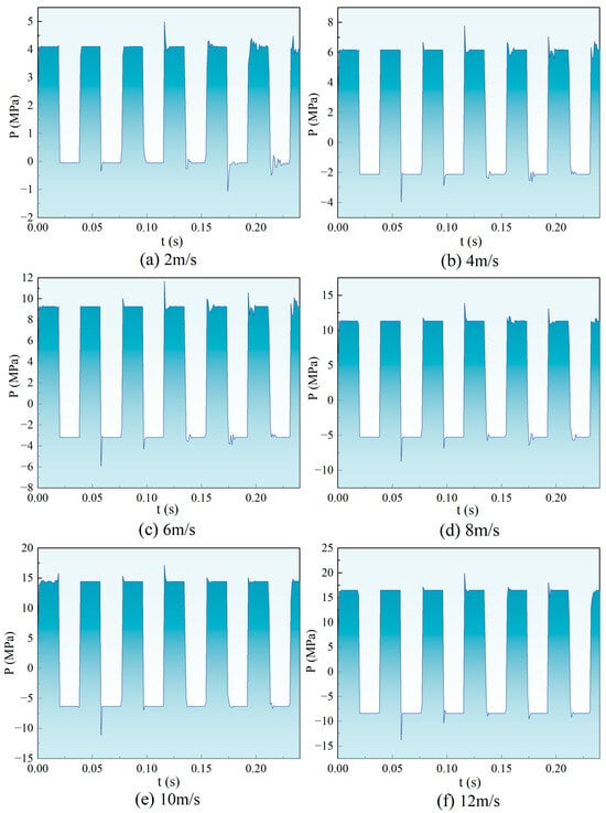
Figure 7.
Variation of water hammer pressure at valves at different flow rates.
By fitting the simulated data, it can be determined that when the flow velocity increases from 2 m/s to 12 m/s, the stable output value P of the water hammer pulse pressure has a linear relationship with the flow velocity V. As shown in Table 4, the larger the initial flow velocity, the greater the pressure output after the occurrence of the water hammer stabilizes.
Table 4.
Water hammer pressure change laws at different flow rates.
3.3. Simulations on the Crack Propagation Patterns in Coal
3.3.1. Comparison of the Fracture Evolution Processes
By comparing the fracture evolution process under static pressure and water hammer pressure in Figure 8, it can be observed that under both static and water hammer pressures, the coal body generally produces two main fractures extending through the fracturing holes, presenting a “butterfly-shaped” morphology extending towards the distal end.
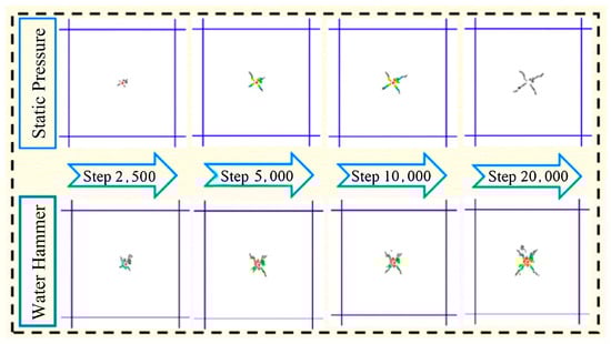
Figure 8.
Fracture evolution under hydrostatic and water hammer pressures.
However, the extension length of the main fractures produced under water hammer action is not as long as those generated under static pressure. The fractures produced in the coal body under static pressure are relatively simple. In contrast, under water hammer pressure, the damage to the coal body is more severe, with more complex development of secondary fractures, deriving numerous interconnected fractures and forming a more complex fracture network. Compared to static hydraulic fracturing, water hammer fracturing, due to its cyclic pulse loading characteristics, has an advantage in the number of fractures formed, making it easier to generate new secondary fractures from the main fractures, which is more conducive to post-fracturing drainage work. However, the extension length of its main fractures often cannot compare with that of static hydraulic fracturing.
3.3.2. Analysis of Crack Initiation Pressure and Number of Cracks
To reflect the differences in fracture evolution characteristics more directly, the simulation will compare and analyze the effects and propagation rules of crack initiation under different loading conditions by monitoring the number of cracks and the initiation pressure.
Through simulation, it is found that under the same stress level, the initiation pressure under static pressure and water hammer action is 24 and 19.5 MPa, respectively. The initiation pressure under water hammer action is lower than that under static pressure. Literature discovered through experiments that coal samples have a “threshold” for fatigue failure under cyclic loading [,]. Additionally, even under loads below the fatigue failure threshold, cyclic loading and unloading can cause a certain degree of fatigue damage, aligning with the research conclusions obtained from the simulation.
As shown in Figure 9, during the crack initiation stage, the difference in the number of cracks under different pressures is small, and the initial number of cracks mainly depends on the model and parameter settings, with little influence from the form of pressure application at this stage.
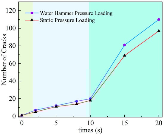
Figure 9.
Comparison of the number of fractures under hydrostatic and water hammer pressures.
During the slow growth stage of cracks, the fracturing simulation continues, and the number of cracks slowly increases. The number of cracks under static pressure and water hammer action reaches 18 and 20 at the 10th second, respectively, close to each other. During the rapid growth stage of cracks, the rate of new crack formation accelerates. At the 20th second, the number of cracks under static pressure and water hammer action reaches 97 and 110, respectively. Under static pressure, the main fractures extend towards the distal end but remain simple in morphology, while under water hammer pressure, a large number of new cracks interconnect, forming a more complex fracture network (see Figure 8).
As shown in Figure 9, the repetitive action of pulsating water hammers leads to periodic and reciprocal variations in hydraulic energy, which enhances the fatigue damage to the coal body and promotes localized damage and deformation.
During the water hammer fracturing process, the coal body is subjected to cyclic rectangular shock wave loads with alternating peak pressure characteristics. When these loads act on the coal body, high-stress concentration occurs at the crack tips, resulting in displacement deformation, crack propagation, and energy dissipation. This leads to an increase in irreversible deformation, a decrease in the elastic modulus of the coal body, and the development of damage. As the cyclic loading continues, internal fractures in the coal body gradually connect, ultimately forming macroscopic fractures.
3.4. Fracture Evolution Patterns Under Different Water Hammer Pressure Amplitudes
The previous sections have investigated the characteristics of pressure waves and the variation rules of pressure amplitude generated by water hammer under different initial pressures and flow rates through experimental and numerical simulations. It is found that the initial state of the fluid directly influences the peak value of the water hammer pressure wave during its occurrence, which is a critical factor affecting the fracturing effect. This section analyzes the development patterns of fractures under different pressure amplitudes of 2, 4, 6, 8, 10, 12, 14, 16, and 18 MPa at a constant frequency of 20 Hz.
To further quantitatively analyze the evolution of fissures, we employed image processing software ImageJ1.53, using the “pixel method” to calculate the percentage of the generated fissure area, thereby enabling a quantitative analysis of the distribution and development range of fissures. Additionally, during the simulation process, the number of fissure generations at different time intervals under varying pressure amplitudes was analyzed by statistically counting the number of fissures generated at different integration steps to investigate the impact of pressure amplitude variations on the duration of each evolutionary stage.
From Figure 10, it can be observed that the fracturing results vary significantly under different pressure amplitude loading conditions. As the pressure amplitude increases, the number of fractures and their extension range exhibit a clear increasing trend.
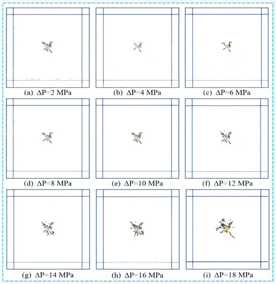
Figure 10.
Fracture development under different water hammer pressure amplitudes.
Figure 11 shows that during the initial fracturing stage, when the pressure amplitude is 2 MPa and 4 MPa, the number of cracks is four each. From 6 MPa to 18 MPa, the number of initial fractures ranges between 5 and 7, indicating that the number of initial fractures does not change significantly with increasing pressure amplitude at the early stage of fracturing. During the slow growth stage of cracks, the number of derived cracks reaches 33 at 2 MPa and 16 at 18 MPa. In this stage, the number of derived cracks decreases as the pressure amplitude increases. This is because when the pressure amplitude is large at the beginning of fracturing, the pressure rises rapidly, changing the stress field of newly formed cracks, preventing the pressure from fully propagating to distant areas, and quickly breaking the connections between nearby particles. When the pressure amplitude is small, crack extension is slow, forming more complex cracks around the borehole and increasing the number of cracks. In the middle and late stages of fracturing, the number of cracks increases with the increase in fracturing amplitude.
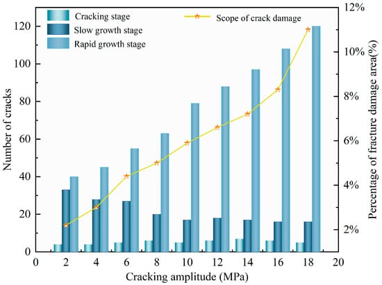
Figure 11.
Changes in the number of fractures at various stages of fracture evolution and the percentage of fracture damage area under different water hammer pressure amplitudes.
When the pressure amplitude increases from 2 MPa to 18 MPa, the number of cracks increases from 40 to 120, and the proportion of the crack damage area increases from 2.2% to 11%. This indicates that the number of cracks generated by secondary fractures continues to increase during their expansion, and an increase in pressure amplitude will promote the formation and expansion of secondary fractures. The development of cracks under different pressure amplitudes, shown in Figure 9, also corroborates this viewpoint.
3.5. Patterns of Crack Propagation Under a Single Fixed Frequency
Previous simulation studies have shown that after a water hammer occurs, the fluid alternates between rising and falling within the output pipeline, and the characteristics of the output pipeline can affect the output frequency of the water hammer pressure wave. In this section, under the same pressure amplitude (10 MPa) loading conditions, the development patterns of fractures under different frequencies of 5, 10, 20, and 30 Hz are analyzed through simulations.
Figure 12 shows the fracturing effects under different water hammer pulse frequencies, with the fracture propagation patterns varying with the pulse frequency.
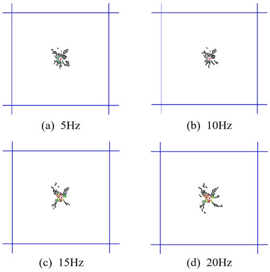
Figure 12.
Fracture evolution process at different frequencies.
Four main fractures were generated under different frequency loading conditions, extending into several new secondary fractures. Due to the cyclic loading, the internal stress in the coal body is repeatedly redistributed, and the edges of the fractures are affected by stress redistribution and alternating stress, resulting in numerous secondary fractures and branches. This leads to complex features in the development of fractures.
Table 5 shows that after applying fracturing with the same duration but different frequencies, different pulse fracturing frequencies result in varying final fracture morphologies and expansion areas. At a pulse frequency of 5 Hz, fracturing produces 108 fractures; under the same pressure amplitude and geostress conditions, the number of fractures decreases to 101 and 97 at 10 Hz and 20 Hz, respectively; at 30 Hz, there are 105 fractures. During high-frequency fracturing, the fracture propagation rate increases, leading to rapid model rupture with uniform fracture size and morphology, resulting in higher rupture efficiency. However, low-frequency fracturing has more significant advantages: firstly, it significantly reduces the initiation pressure, slows down the fracture propagation rate, and extends the action time; secondly, it promotes full expansion and evolution of internal fractures in the model, exacerbates fatigue damage effects, and forms complex fracture planes.
Table 5.
Comparison of the number of fractures at different frequencies.
The above findings indicate that higher frequencies do not necessarily yield better fracturing results; low-frequency pulse fracturing is more suitable, which aligns with previous experimental studies; under the same pressure, lower pulse frequencies result in more comprehensive fracture development.
3.6. Patterns of Crack Propagation Under Variable Frequency Conditions
Figure 13 depicts fracture expansion patterns under variable frequency action. It shows that under the same geostress and pressure amplitude conditions, by alternately applying pulse frequencies of 5 and 30 Hz for fracturing coal, it is found that a segmented fracturing method starting with a 5 Hz frequency followed by switching to a 30 Hz frequency can more effectively promote the formation and expansion of cracks compared to other frequency combinations. This loading strategy, which starts with a low frequency and then switches to a high frequency, utilizes the differential effects of different frequencies on crack growth dynamics, optimizing the development of the fracture network and thus improving fracturing efficiency.
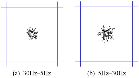
Figure 13.
Fracture expansion patterns under variable frequency action.
4. Conclusions
This paper numerically simulated the propagation characteristics of water hammer pulsation pressure and the laws of fracture propagation in coal bodies with their experimental validation. The following conclusions were drawn:
- (1)
- Experiments show that as the initial water flow velocity increases from 0.6 m/s to 1.2 m/s, the amplitude of pressure fluctuation after the occurrence of water hammer rises from 0.55 MPa to 1.29 MPa, with the pulse pressure variation rate reaching 127%, 127%, 148%, and 139%, respectively. The higher the initial water pressure, the greater the energy of the water body driven into the water hammer device, resulting in a larger peak value of the instantaneous pulse pressure wave generated after the water hammer effect, while the pulse pressure trough is lower than the initial water pressure, thereby forming a larger pressure fluctuation amplitude.
- (2)
- Based on the results of the water hammer numerical simulations, the magnitude of the water hammer pressure is significantly influenced by the initial flow velocity and pressure. As the flow velocity changes, the peak value of the water hammer pressure fluctuates within a certain range. When the initial flow velocity increases from 2 m/s to 12 m/s, the generated water hammer pressure peak rises from 4.99 MPa to 19.91 MPa. Under static pressure conditions, the coal body reaches its ultimate failure limit, resulting in relatively simple fractures, primarily two main fractures passing through the fracturing hole. In contrast, under water hammer pressure conditions, the coal body experiences more severe damage, forming two main fractures and developing more complex secondary fractures. This characteristic of cyclic impact makes the coal body more prone to fatigue damage, promoting the formation of additional complex secondary fractures, which provides an advantage in the number of fractures formed and is more beneficial for subsequent gas extraction operations.
- (3)
- Through fracture propagation simulation, it is found that when the pressure amplitude increases from 2 MPa to 18 MPa, both the number of fractures and the extent of damage expansion show an increasing trend; the effects of different frequencies on fracturing results are more complex, with high-frequency fracturing resulting in fast fracture propagation rates and uniform size and shape, while low-frequency fracturing leads to slow fracture propagation rates, increased fatigue damage, and more complex fracture development; if variable frequency combinations are used for fracturing, a loading sequence starting with low frequency followed by high frequency is more conducive to fracture propagation evolution.
Low-permeability coal seams are typically located in the deep parts of mines. The high head difference between the surface static water tank and the deep coal seam is precisely suited to provide a high-head inlet force for the water hammer effect, which can generate periodic pulsating high-pressure waves, promoting uniform permeability and infiltration in the coal body. The paper has made preliminary explorations on the application of the water hammer technology for fracturing coal. Future research will focus on experimental studies to further investigate the effects of the water hammer on the coal fracturing process. Additionally, there are currently few devices that can directly output water hammer pressure, and the pressure pulse generated by the water hammer is difficult to sustain and control for continuous and controllable application within a sealed fracturing hole. Therefore, the focus of future research should be on the development of a continuous and controllable water hammer pulse output device.
Author Contributions
Data curation, X.L. and J.F.; Formal analysis, X.L. and J.F.; Investigation, J.N. and X.L.; Resources, J.N. and J.Z.; Validation, J.N. and J.Z.; Visualization, J.N., J.Z. and X.L.; Writing—original draft, J.N. and J.Z.; Writing—review and editing, J.F. All authors have read and agreed to the published version of the manuscript.
Funding
This research was funded by the National Natural Science Foundation of China (No. 52274220 and 52474244).
Data Availability Statement
The data presented in this study are available on request from the corresponding author.
Acknowledgments
The authors gratefully acknowledge the editor and anonymous reviewers for their valuable comments on this manuscript.
Conflicts of Interest
Author Jun Nian was employed by the company Shanxi Coking Coal Group Co., Ltd. The remaining authors declare that the research was conducted in the absence of any commercial or financial relationships that could be construed as a potential conflict of interest.
References
- Ranjith, P.G.; Zhao, J.; Ju, M.; De Silva, R.V.S.; Rathnaweera, T.D.; Bandara, A.K.M.S. Opportunities and Challenges in Deep Mining: A Brief Review. Engineering 2017, 3, 546–551. [Google Scholar] [CrossRef]
- Yuan, A.; Fu, G.; Hou, J. A Multiscale Structural Analysis of Soft and Hard Coal Deposits in Deep High-Gas Coal Seams. Adv. Civ. Eng. 2021, 2021, 8865038. [Google Scholar] [CrossRef]
- Ren, L.; Tang, J.; Pan, Y.; Zhang, X.; Yu, H. Macroscopic fracture mechanism of coal body and evolution characteristics analysis of impact force in deep coal and gas outburst. Sci. Rep. 2023, 13, 15944. [Google Scholar] [CrossRef]
- Qiao, Z.; Li, C.; Wang, Q.; Xu, X. Principles of formulating measures regarding preventing coal and gas outbursts in deep mining: Based on stress distribution and failure characteristics. Fuel 2024, 356, 129578. [Google Scholar] [CrossRef]
- Li, W.; Cui, M.; Hu, C. Research on deep gas geological laws and gas prediction: A case study of the Lvjiatuo coal mine. Environ. Earth Sci. 2023, 83, 26. [Google Scholar] [CrossRef]
- Zhu, Q.; Du, X.; Zhang, T.; Yu, H.; Liu, X. Investigation into the variation characteristics and influencing factors of coalbed methane gas content in deep coal seams. Sci. Rep. 2024, 14, 18813. [Google Scholar] [CrossRef] [PubMed]
- Wang, Z.; Cao, J.; Liu, J.; Li, C. Research on Permeability Enhancement Model of Pressure Relief Roadway for Deep Coal Roadway Strip. Geofluids 2022, 2022, 1342592. [Google Scholar] [CrossRef]
- Li, X.; Si, K.; He, T.; Li, C. Dynamic Effect of Shaped Charge Blasting and Its Application in Coal Seam Permeability Enhancement. ACS Omega 2022, 7, 25353–25365. [Google Scholar] [CrossRef]
- Qiao, Y.; Zhang, Z.; Yuan, D.; Li, L.; Zhao, J. Numerical investigation of the in situ gas explosion fracturing and the enhancement of the penetration in coal seam boreholes. Energy Sci. Eng. 2023, 11, 4128–4140. [Google Scholar] [CrossRef]
- Cao, S.; Wang, X.; Ge, Z.; Guo, Z.; Zhang, L. Experimental study on the damage and fracture mechanism of deep coal beds impacted by water jets at different temperatures. Fuel 2024, 371, 132121. [Google Scholar] [CrossRef]
- Rehbinder, G. Slot cutting in rock with a high speed water jet. Int. J. Rock Mech. Min. Sci. Geomech. Abstr. 1977, 14, 229–234. [Google Scholar] [CrossRef]
- Rahman, M.K.; Joarder, A.H. Investigating production-induced stress change at fracture tips: Implications for a novel hydraulic fracturing technique. J. Petrol. Sci. Eng. 2006, 51, 185–196. [Google Scholar] [CrossRef]
- Huang, B.; Liu, C.; Fu, J.; Guan, H. Hydraulic fracturing after water pressure control blasting for increased fracturing. Int. J. Rock Mech. Min. Sci. 2011, 48, 976–983. [Google Scholar] [CrossRef]
- Detournay, E. Mechanics of Hydraulic Fractures. Annu. Rev. Fluid Mech. 2016, 48, 311–339. [Google Scholar] [CrossRef]
- Wei, C.; Li, S.; Yu, L.; Zhang, B.; Liu, R.; Pan, D.; Zhang, F. Study on Mechanism of Strength Deterioration of Rock-Like Specimen and Fracture Damage Deterioration Model Under Pulse Hydraulic Fracturing. Rock Mech. Rock Eng. 2023, 56, 4959–4973. [Google Scholar] [CrossRef]
- Guanhua, N.; Baiquan, L.; Cheng, Z. Impact of the geological structure on pulsating hydraulic fracturing. Arab. J. Geosci. 2015, 8, 10381–10388. [Google Scholar] [CrossRef]
- Yu, X.; Chen, A.; Hong, L.; Zhai, C.; Regenauer-Lieb, K.; Sang, S.; Xu, J.; Jing, Y. Experimental investigation of the effects of long-period cyclic pulse loading of pulsating hydraulic fracturing on coal damage. Fuel 2024, 358, 129907. [Google Scholar] [CrossRef]
- Li, Q.; Lin, B.; Zhai, C. A new technique for preventing and controlling coal and gas outburst hazard with pulse hydraulic fracturing: A case study in Yuwu coal mine, China. Nat. Hazard. 2015, 75, 2931–2946. [Google Scholar] [CrossRef]
- Ramos, J.; Wang, W.; Diessl, J.; Oliver, N.; Bruno, M.S. Advanced Hydraulic Fracture Characterization Using Pulse Testing Analysis. Rock Mech. Rock Eng. 2019, 52, 5047–5069. [Google Scholar] [CrossRef]
- Jingna, X.; Jun, X.; Guanhua, N.; Rahman, S.; Qian, S.; Hui, W. Effects of pulse wave on the variation of coal pore structure in pulsating hydraulic fracturing process of coal seam. Fuel 2020, 264, 116906. [Google Scholar] [CrossRef]
- López-Comino, J.A.; Cesca, S.; Heimann, S.; Grigoli, F.; Milkereit, C.; Dahm, T.; Zang, A. Characterization of Hydraulic Fractures Growth During the Äspö Hard Rock Laboratory Experiment (Sweden). Rock Mech. Rock Eng. 2017, 50, 2985–3001. [Google Scholar] [CrossRef]
- Zang, A.; Zimmermann, G.; Hofmann, H.; Stephansson, O.; Min, K.-B.; Kim, K.Y. How to Reduce Fluid-Injection-Induced Seismicity. Rock Mech. Rock Eng. 2019, 52, 475–493. [Google Scholar] [CrossRef]
- Ding, C.; Huang, Y.; Chen, H.; Zhang, L.; Meng, B.; Gao, Y. New Hydraulic High-Pressure Impulse Generator for Long-Duration Impulse Tests. Appl. Sci. 2021, 11, 901. [Google Scholar] [CrossRef]
- Xi, X.; Yang, S.; McDermott, C.I.; Shipton, Z.K.; Fraser-Harris, A.; Edlmann, K. Modelling Rock Fracture Induced By Hydraulic Pulses. Rock Mech. Rock Eng. 2021, 54, 3977–3994. [Google Scholar] [CrossRef]
- Gao, X.; Shi, Y.; Shen, C.; Wang, W. Experimental investigation on hydraulic fracturing under self-excited pulse loading. Environ. Earth Sci. 2022, 81, 313. [Google Scholar] [CrossRef]
- Wang, P.; Shi, D.; Cui, X.; Su, B.; Li, G.; Ma, C. Study on dynamic characteristics of transient high-speed water jet impacting into and out water. Ocean Eng. 2023, 286, 115670. [Google Scholar] [CrossRef]
- Li, H.; Huang, B.; Xu, H. The Optimal Sine Pulse Frequency of Pulse Hydraulic Fracturing for Reservoir Stimulation. Water 2022, 14, 3189. [Google Scholar] [CrossRef]
- Hou, Y.; Peng, Y.; Liu, Y.; Chen, Z.; Fan, B.; Yin, Z.; Zhang, G. Influence of Increasing Mean Stress on Fatigue Properties of Shale during Pulsating Hydraulic Fracturing. Energy Fuels 2022, 36, 14174–14186. [Google Scholar] [CrossRef]
- Zhu, G.; Dong, S. Discrete element simulation model of pulsating hydraulic fracturing considering fatigue damage. Geomech. Geophys. Geo-Energy Geo-Resour. 2022, 8, 119. [Google Scholar] [CrossRef]
- Zhu, G.; Hanane, B.; Dong, S.; Jin, Z.; Li, W. Dynamic stress response and fatigue characteristics of tight sandstone reservoirs with pulsating hydraulic fracturing. Bull. Eng. Geol. Environ. 2024, 83, 490. [Google Scholar] [CrossRef]
- He, P.; Xiong, J.; Lu, Z.; Pan, L.; Qin, D. Study of Pulse Wave Propagation and Attenuation Mechanism in Shale Reservoirs During Pulse Hydraulic Fracturing. Arab. J. Sci. Eng. 2018, 43, 6509–6522. [Google Scholar] [CrossRef]
- He, P.; Lu, Z.; Deng, Z.; Huang, Y.; Qin, D.; Ouyang, L.; Li, M. An advanced hydraulic fracturing technique: Pressure propagation and attenuation mechanism of step rectangular pulse hydraulic fracturing. Energy Sci. Eng. 2023, 11, 299–316. [Google Scholar] [CrossRef]
- Chang, H.; Yang, J.; Wang, Z.; Peng, G.; Lin, R.; Lou, Y.; Shi, W.; Zhou, L. Efficiency optimization of energy storage centrifugal pump by using energy balance equation and non-dominated sorting genetic algorithms-II. J. Energy Storage 2025, 114, 115817. [Google Scholar] [CrossRef]
- Yu, X.; Cheng, Z.; Hong, L.; Zhao, N.; Chen, A. Prediction of the Effects of Pulsating Hydraulic Fracturing on the Porous Structure and Permeability of Coal Based on NMR and AE Spectra. ACS Omega 2024, 9, 21440–21449. [Google Scholar] [CrossRef]
- Peng, Y.; Wei, S.-J.; Zhang, G.-Q.; Zhou, D.-W.; Xu, C.-C. Multiple damage zones around hydraulic fractures generated by high-frequency pulsating hydraulic fracturing. Pet. Sci. 2024, 21, 2688–2702. [Google Scholar] [CrossRef]
- Zhang, Z. Wave tracking method of hydraulic transients in pipe systems with pump shut-off under simultaneous closing of spherical valves. Renew. Energy 2019, 132, 157–166. [Google Scholar] [CrossRef]
- Xie, H.; Li, X.; Shan, C.; Xia, Z.; Yu, L. Study on the Damage Mechanism and Energy Evolution Characteristics of Water-Bearing Coal Samples Under Cyclic Loading. Rock Mech. Rock Eng. 2023, 56, 1367–1385. [Google Scholar] [CrossRef]
- Liu, X.; Cai, D.; Gu, Z.; Zhang, S.; Zhou, X.; Gao, A. Analysis of progressive damage and energy consumption characteristics of gas-bearing coal under cyclic dynamic loads. Energy 2024, 306, 132419. [Google Scholar] [CrossRef]
Disclaimer/Publisher’s Note: The statements, opinions and data contained in all publications are solely those of the individual author(s) and contributor(s) and not of MDPI and/or the editor(s). MDPI and/or the editor(s) disclaim responsibility for any injury to people or property resulting from any ideas, methods, instructions or products referred to in the content. |
© 2025 by the authors. Licensee MDPI, Basel, Switzerland. This article is an open access article distributed under the terms and conditions of the Creative Commons Attribution (CC BY) license (https://creativecommons.org/licenses/by/4.0/).