Abstract
Modern weeding technologies include chemical weeding, non-contact methods such as laser weeding, and conventional mechanical inter-row cultivation characterized by soil loosening and weed uprooting. For maize, mechanical inter-row cultivation is key to cutting herbicide use and enhancing the soil–crop environment. This study developed a vision-guided intelligent inter-row cultivator with electric lateral shifting—its frame fabricated from Q235 low-carbon structural steel and assembled mainly via bolted and pinned joints—that computes real-time lateral deviation between the implement and crop rows through maize plant recognition and crop row fitting and uses delay compensation to command a servo-electric cylinder for precise ±15 cm inter-row adjustments corresponding to 30% of the 50 cm row spacing. To test the system’s dynamic response, 1–15 cm-commanded lateral displacements were evaluated at 0.31, 0.42, and 0.51 m/s to characterize the time-displacement response of the servo-electric shift mechanism; field tests were conducted at 0.51 m/s with three 30 m passes per maize growth stage to collect row-guidance error and root-injury data. Field results show that at an initial offset of 5 cm, the mean absolute error is 0.76–1.03 cm, and at 15 cm, the 95th percentile error is 7.5 cm. A root damage quantification method based on geometric overlap arc length was established, with rates rising with crop growth: 0.12% at the V2 to V3 stage, 1.46% at the V4 to V5 stage, and 9.61% at the V6 to V8 stage, making the V4 to V5 stage the optimal operating window. Compared with chemical weeding, the system requires no herbicide application, avoiding issues related to residues, drift, and resistance management. Compared with laser weeding, which requires high tool power density and has limited effective width, the tractor–implement system enables full-width weeding and shallow inter-row tillage in one pass, facilitating integration with existing mechanized operations. These results, obtained at a single forward speed of 0.51 m/s in one field and implement configuration, still require validation under higher speeds and broader field conditions; within this scope they support improving the precision of maize mechanical inter-row cultivation.
1. Introduction
Weeds in fields compete with crops for light, water, and nutrients, causing potential yield losses [1]. The environmental pollution associated with chemical weeding has drawn global concern, and regions such as the European Union and the United States are promoting non-chemical weed control to achieve green prevention and control [2,3]. Recent progress in non-chemical weed management has produced several promising alternatives, including laser or electric weeding robots that thermally destroy individual weeds near the crop row [4], and flame or other thermal systems that kill seedlings by short, intense heat shocks [5]. Agronomic studies further emphasize cultural measures such as mulching, adjusted sowing dates, and transplanting to reduce early weed pressure and herbicide demand [6]. However, these approaches typically face trade-offs in energy input, safety constraints, effective working width, or strong dependence on local climate and labor organization. By contrast, mechanically guided inter-row cultivation remains a robust non-chemical option that can be mounted on existing tractors, delivers high field capacity at practical speeds, and directly integrates soil loosening with weed removal. A concise comparison of these non-chemical weeding technologies is provided in Appendix A (Table A1). Therefore, despite its own challenges related to guidance accuracy and potential root injury, mechanical inter-row weeding continues to be a practical and competitive non-chemical contender in row crops. Against this backdrop, AI-enabled mechanical weeding has emerged as a leading non-chemical alternative to herbicides due to its efficiency and adaptability [7,8]. Such equipment identifies crops and weeds and actuates mechanisms to operate between rows, performing soil loosening and weed removal [9,10]. Compared with conventional methods, intelligent weeding reduces chemical inputs and labor intensity; however, under complex field conditions—variable illumination, plant occlusion, irregular row lines, and terrain undulation—it remains difficult to maintain row alignment. Therefore, robust, high-accuracy row-guided inter-row cultivation that also minimizes root-zone injury is urgently needed to support green prevention and control and expand non-chemical management coverage [11,12].
Cordill et al. [13] designed a mechanically actuated opening–closing knife for intra-row weeding and completed engineering validation of both the tool structure and the control workflow, demonstrating the feasibility of mechanical intra-row weeding. Jiang et al. [14] developed a field system combining visual recognition with an opening–closing knife: crop positions are detected in images and the tool is triggered in real time, achieving an 80.25% intra-row weeding rate at 3.28 km/h, which shows the capability of vision-triggered operation at near-conventional speeds. These studies offer effective directions in actuator design, visual triggering, and electric actuation accuracy, but control commands are generally driven directly by detected offsets without compensating the end-to-end latency from perception to the blade. When travel speed increases or the path has curvature, this latency converts to an in-soil positional bias, enlarging operational error and raising the risk of root-zone injury. Pérez-Ruiz et al. [15,16] proposed automatic intra-row knife control based on crop-row centerline tracking, integrating high-precision positioning with a lateral shift actuator for closed-loop control, achieving an 8 mm row-following error and verifying centimeter-level field accuracy. Zheng et al. [17] developed an electrically driven opening–closing knife for cabbage, reaching 96% weeding accuracy with a 0.68% root-injury rate, and Li et al. [18] designed a seedling-based localization approach with shielded cutting tools, validating early-stage weeding and seedling safety. Nonetheless, most work focuses on outcomes and alignment error, lacking geometric quantification of root-zone spatial risk and system-level analysis, which makes small injury regions difficult to identify.
Zhao et al. [19] presented an intra-row system that directly converts vision-detected lateral deviation into a lateral control input for the weeding knife. Commercial implements [20,21,22] commonly adopt vision-guided inter-row weeding by integrating cameras with lateral actuators to increase coverage, and their lateral control typically applies full compensation to the measured offset. Nørremark et al. [23,24] combined RTK-GPS navigation, a lateral mechanism, and a rotary hoe, opening and closing tines over time according to a sowing-stage crop map, while maintaining row following with a fixed error threshold. In prevailing approaches, the lateral offset is treated as the commanded displacement. When the offset is large, the actuator cannot complete the required travel within one control cycle, subsequent commands accumulate, and error grows. Outlier plants also reduce reliability at large offsets, so full-magnitude commands can amplify error and cause root injury; a single full-width shift consumes excessive cycle time, reducing reachability in the next cycle; with path curvature or terrain disturbance, overshoot may occur and even drive the mechanism to its stroke limits. The fundamental gap is the absence of lateral-magnitude constraints, per-cycle reachability checks, and suppression of large-offset uncertainty, together with triggering and control strategies matched to actuator delay.
Most existing vision-based inter-row guidance systems do not explicitly model or compensate the perception–control–actuation delay along the forward direction; their lateral correction stroke and dynamic bandwidth are seldom evaluated over the full operating range, and quantitative, spatially explicit assessment of root-damage risk along the crop row is almost never reported. As a result, even when centimeter-level tracking errors are achieved, it remains unclear how much of the root zone is actually endangered at different growth stages and how early inter-row cultivation should be scheduled to keep the risk within an acceptable range.
To address these issues, this study develops a vision-based, electrically actuated, row-guided inter-row cultivator and constructs a coordinated control framework comprising delay compensation and bounded row-alignment correction. In the proposed implement, a servo-electric cylinder provides lateral shifting of the cultivator relative to the crop rows. Compared with hydraulic lateral-shift systems widely used on larger inter-row cultivators, this electric actuator offers finer position resolution and repeatability, a more compact drive with no risk of oil leakage, and straightforward integration with electronic controllers and delay-compensation algorithms, making it particularly suitable for achieving centimeter-level lateral tracking on a low-speed, medium-width maize cultivator. The total latency of perception, communication, and actuation is forward-accounted to the blade–soil engagement point and executed in advance when lateral offset exists, ensuring the blade reaches the target position. Lateral correction adopts two-level saturation with hysteresis and travel buffering. The cultivation trajectory and root-system distributions at each leaf stage are overlaid in a unified coordinate system, and the geometric overlap arc length is computed and visualized to quantify root injury. This provides reliable technical support for inter-row cultivation in the maize seedling stage.
2. Materials and Methods
In this study, we designed a vision-based row-guided inter-row cultivator consisting of a lateral shift mechanism and four inter-row weeding units. The lateral shift mechanism forms the main structure, and a lateral connection plate serves as the key working element for row alignment. The device integrates a deep learning maize-row detection module, a servo-driven lateral guidance controller, and the inter-row weeding units to enable precise and efficient row-guided cultivation in field conditions.
2.1. Design of the Row-Guidance Mechanism for Inter-Row Cultivation
2.1.1. Operating Principle of the Row-Guidance Mechanism for Inter-Row Cultivation
For row-guided inter-row cultivation in maize fields, the implement comprises a network camera (Logitech Inc, Lausanne, Switzerland), an NVIDIA Jetson Orin NX (NVIDIA, Santa Clara, CA, USA), a C37 controller (Heesn Microelectronics Technology Co., Ltd., Suzhou, China), a servo drive (model FD144S-CB-005, Kinco Electric Co., Ltd., Shenzhen, China), and a servo-electric cylinder with a lateral-shift mechanism (model JC804-800-300-71.4-1Kw, Changzhou Jiechuan Electromechanical Equipment Co., Ltd., Changzhou, China). The camera acquires images of multiple maize rows within the FoV, and the Jetson detects stem tips, fits the crop-row lines, and computes the geometric midpoint between adjacent rows to generate the inter-row centerline. The system then computes the lateral deviation e with respect to this centerline. The C37 converts e into a lateral command and, given available lateral travel of ±15 cm (total 30 cm), reserves a 2–3 cm end margin before commanding the servo drive; the cylinder executes the side shift, aligning the cultivation band with the target inter-row centerline in real time. The row spacing S is 50 cm, and the cultivation-band width is 30 cm. During operation, the controller is tuned for robust performance under the constraint of minimal root-zone intrusion, characterized by rapid decay of the lateral deviation and stable tracking of the crop-row centerline, thereby achieving safe coverage and efficient maize inter-row cultivation, as shown in Figure 1.
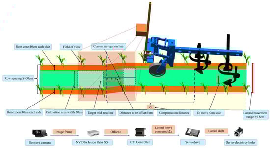
Figure 1.
Operating principle diagram of the inter-row cultivator.
2.1.2. Key Structural Design
The structure of the row-guided inter-row cultivator consists of the adjustable depth unit, tillage contour-following mechanism, speed measurement unit, and lateral-shift mechanism unit, as shown in Figure 2. The adjustable depth design (Figure 2①) includes a knob, depth display, and a telescopic tube, allowing for quick adjustment and locking of the soil penetration depth to ensure consistent penetration across multiple rows. The tillage contour-following mechanism (Figure 2②) includes the depth control wheel, providing vertical freedom to track surface undulations, thus stabilizing the entry angle and depth. The speed measurement design (Figure 2③) consists of a tachometer wheel group and an encoder, which output real-time speed measurements to serve as the source for delay compensation and early triggering. The lateral-shift design (Figure 2④–⑥) includes the main beam, second beam, connecting part, and transverse shifting plate. The transverse shifting pulley and bearing reduce friction and ensure lateral straightness. The electric cylinder and servo drive system perform lateral displacement, with the servo motor and driver rigidly connected to the transverse shifting mechanism via bolts. The rated power, speed, torque, and voltage of the servo motor are 1000 W, 3000 rpm, 3.18 N·m, and 48 V, respectively, and the lateral actuator provides single-side travel of 15 cm. Multiple structures work in coordination under the unified frame. The speed measurement unit provides real-time speed information, the lateral-shift structure executes lateral correction, the adjustable depth structure allows for depth adjustment based on terrain conditions, and the contour-following mechanism absorbs terrain disturbances, thus providing a robust mechanical and informational foundation for row-guided inter-row cultivation operations.
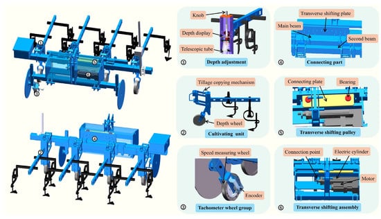
Figure 2.
Structure diagram of the inter-row cultivator.
The row-guided inter-row cultivation system developed in this study consists of a servo-electric cylinder, lateral-shift mechanism, and rear crossbeam, forming a single-degree-of-freedom lateral actuation unit. The electric cylinder and lateral-shift plate are rigidly connected with bolts, and the axial extension and retraction of the electric cylinder directly translate into lateral motion of the lateral-shift plate. The lateral-shift plate is connected to the rear crossbeam, which collectively drives four inter-row cultivation units to move laterally in synchronization. The controller issues displacement commands based on the lateral offset detected by the vision system, achieving fine, rapid lateral adjustments. This ensures that all four units remain aligned within the operating plane. As a result, the system is able to provide the required displacement during row-guided correction, balancing positioning accuracy, operational efficiency, and consistency under varying terrain and row spacing conditions.
2.2. Crop Row Detection and Row-Guidance Control System
2.2.1. Crop Row Detection and Row-Guidance Communication
The maize seedling images used in the experiments were acquired at the National Precision Agriculture Research and Demonstration Base in Xiaotangshan, Changping District, Beijing, China, from 1 July to 20 July 2025, between 09:00 and 16:00. The images were captured using a Logitech C930c camera (Logitech Inc., Lausanne, Switzerland) at a resolution of 1920 × 1080. To ensure background complexity and dataset diversity, images were collected under various weather conditions, illumination levels, and growth stages, yielding a total of 1987 images. Maize seedlings in the dataset were annotated as target objects using the LabelImg software (Version 1.8.6), and the images were divided into training, validation, and test sets in a ratio of 8:1:1. Our group developed a deep learning-based algorithm for real-time crop-row recognition and localization of maize in the field [25]. The model trained in this study is a two-class detector designed to distinguish between two categories: “maize” and “non-maize (weed)”. After 100 training epochs, it achieved a precision (P), recall (R), and mean average precision (mAP) of 96.7%, 95.8%, and 96.2%, respectively. Crop-row detection was performed using a segmentation model based on You Only Look Once, version 8, small (YOLOv8s) [26]. The complete workflow of this crop-row detection and correction process is illustrated in Figure 3: Online stem centroids are used as key points; K-means clustering determines the number of rows [27,28]; confidence-weighted least squares fits the left and right crop-row centers [29]; from these two centers a geometric inter-row centerline is constructed, and the lateral offset is obtained by comparison with this centerline. After calibration, the pixel offset is mapped to physical lateral displacement [30]. The recognition-to-command update rate is 3 Hz. The host computer, a Jetson Orin NX (NVIDIA, Santa Clara, CA, USA), communicates with the C37 controller over USB-CAN, using a fixed 16-byte packet to issue row-guidance commands: AA 01 00 08 00 00 00 01 00 05 00 00 00 00 00 00. The frame contains key fields: a header, command ID, direction flag, and offset count, with remaining bytes reserved for extension; 00 denotes left and 01 denotes right, and the offset is encoded as a hexadecimal count. Upon reception, the lower-level controller converts the offset count to a lateral displacement command for the servo-electric cylinder using calibration coefficients and executes it in closed loop, while reporting actual displacement and status, thereby achieving row-guided correction and stable tracking.
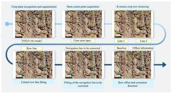
Figure 3.
Flowchart of crop row detection.
To characterize the overall delay between the completion of image processing on the Jetson Orin NX and the transmission of the command to the C37 controller, we performed an end-to-end timing test of the communication chain. In this test, the vision program recorded a timestamp immediately after finishing YOLOv8s-Seg inference and computing the lateral offset on the Orin NX. The communication thread then packaged the offset into a fixed 16-byte row-guidance frame and sent it via the USB–CAN interface. A second timestamp was recorded when this frame was actually placed on the CAN bus and accepted by the interface. This procedure was repeated over multiple control cycles under typical operating conditions, and the average difference between the two timestamps was taken as the overall perception–communication delay from the Orin NX to the C37. This experimentally calibrated delay value was then used as the perception–communication component of the total system delay in the delay-compensation model.
2.2.2. Hardware Architecture of the Control System
The control system consists of a C37 controller (Heesn Microelectronics Technology Co., Ltd., Suzhou, China), a servo drive, a servo motor, an encoder (model BRT38-ROM-65535-D1-RT1-IP68, Shenzhen Boshida Technology Co., Ltd., Shenzhen, China), and a servo-electric cylinder. Serving as the core module, the C37 communicates with the NVIDIA Jetson Orin NX to coordinate all system components and execute row-guidance control for inter-row cultivation.
2.2.3. Row-Guidance Control Model
The system operates by leveraging the NVIDIA Orin NX platform in combination with deep learning algorithms to extract the row information of two maize rows and calculate the geometric center of the row lines. By comparing this with the camera’s field of view centerline, the lateral deviation is computed and used as the lateral control input, which is then transmitted to the C37 controller. During operation, the speed encoder provides real-time speed data for constant speed operation, and the controller calculates the compensation time based on the ratio between the distance from the camera’s centerline to the cultivator and the operating speed, correcting the delay between image recognition and execution control. Ultimately, once the camera identifies and passes the target plant, the controller sends an enable signal to the servo driver, prompting the servo motor to adjust the extension of the servo-electric cylinder, ensuring precise adjustment and stable operation of the cultivator.
The system detects the two maize plants in real time using the camera, calculates the deviation between them and the current position of the lateral shift mechanism, and then transmits the offset to the C37 controller, as shown in Figure 4. Based on the constant forward speed v of the implement and the fixed distance d between the camera and the cultivator blade, the system calculates the trigger time for the servo-electric cylinder. In this way, when the lateral offset changes, the lateral-shift mechanism can reach the target position in time and with high accuracy. Additionally, in addition to real-time offset calculation, the system must account for various delay factors, including image processing, data transmission, and the response time of the servo-electric cylinder. The time required for lateral shift is calculated in real time, while other delay factors are determined through experimental calibration. Finally, these delays, along with the offset information, are comprehensively calculated to ensure that the lateral shift action is triggered at the precise moment, maintaining operational stability and accuracy. The formula for calculating delays is:
where is the delay compensation distance in meters, is the distance from the FoV center to the cultivator blade in meters, is the real-time constant speed of the machine in meters per second, and is the total system delay time in seconds.
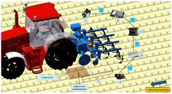
Figure 4.
Schematic diagram of the control system delay. (a) Network camera; (b) NVIDIA Jetson Orin NX; (c) C37 controller; (d) servo drive; (e) servo-electric cylinder; 1. Maize identification and positioning time; 2. communication time; 3. servo driver response time; 4. opening and closing time.
To accurately determine the real-time position and velocity of the implement, the C37 controller accomplishes this by reading the encoder pulse signals from the speed measurement wheel in real time. The implement’s speed is calculated by multiplying the pulse frequency by the distance represented by each pulse. The traveled distance is determined by counting the number of encoder pulses, with each pulse from the encoder indicating that the implement has moved a fixed distance along the path. To prevent the pulse count from overflowing, when the encoder pulse count reaches 1000, the counter resets to zero and starts again, incrementing the counter by 1. This ensures that the system can continuously and accurately track the implement’s motion path and speed changes:
is the travel speed of the implement (m/s); is the pulse frequency (Hz); is the travel distance per pulse of the implement (m/pulse); is the travel distance of the implement (m); is the counter value; and is the pulse count.
2.2.4. Row-Guidance Control Strategy
The row-guidance control adopts a two-stage lateral correction rule. The vision module outputs the lateral offset in real time, and the actuator is a lateral-shift servo-electric cylinder on the lateral-shift mechanism. The neutral position is centered, with 15 cm per side and a 30 cm total stroke length. The output speed remains constant, and the stages are defined as follows: when the offset is less than or equal to 15 cm, the controller issues the target displacement command; for offsets between 15 cm and 20 cm, it commands 80% of the target displacement; when the estimated offset exceeds 20 cm, lateral displacement is limited to 20 cm to avoid excessive shifting caused by failure to suppress abnormal data. To avoid frequent switching near the threshold, a hysteresis band of 1.5–2 cm is applied around 15 cm. To reduce overshoot, a 2 cm stroke buffer is reserved before the lateral movement reaches the travel limit, and within each control cycle, the commanded displacement must not exceed the remaining safe stroke. A per-cycle displacement limit is enforced: the maximum lateral displacement allowed in each control cycle is limited to 80% of the distance the cylinder can complete at its rated maximum speed within that cycle. To ensure the target position is reached on time, the geometric distance from the camera to the blade is converted into an available lead time based on the current travel speed of the implement, and the required lateral travel time is estimated based on the current target displacement and the allowable speed of the servo-electric cylinder. If the required time may exceed the lead time, the controller triggers lateral motion earlier. This adjustment only affects the trigger time and does not change the two-stage rule (Figure 5).
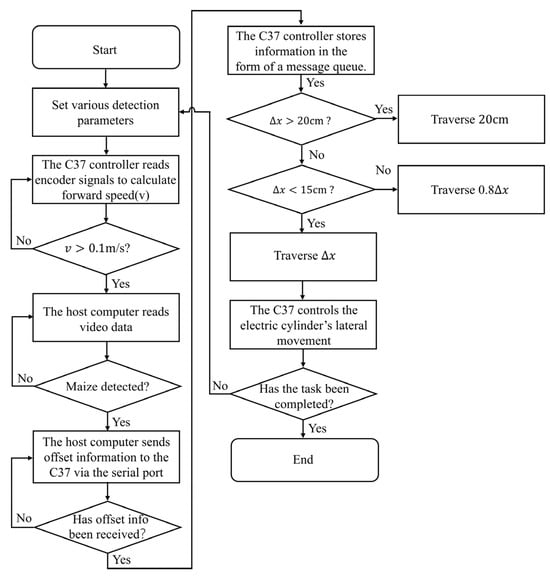
Figure 5.
Row-guidance control system flowchart.
2.3. Experiments
2.3.1. Controlled-Site Tests
- (1)
- Dynamic Response Test of the Row-Guidance Lateral-Shift Mechanism
This test was designed to measure the total time for the servo-electric cylinder to move from the start position to the target position and to compute the average speed, supporting the setting of the look-ahead compensation parameter and the per-cycle displacement limit. After homing, the test began with the target speed, acceleration, deceleration, and control period held constant; the end-of-stroke buffer and in-position threshold were set uniformly, and the stroke limit was not contacted. Target displacements were set from 1 to 20 cm in 1 cm steps and executed sequentially for 20 runs. In the same control cycle that issued the start command, the controller recorded the start time ; the servo drive’s status word, position, and speed were sampled at 1 ms; when the in-position flag in position mode was first set, the end time was recorded. The single-run response time was defined as , and the average speed was obtained by dividing the target displacement by this response time; after each run the cylinder homed before the next test. Throughout, the target and actual speed, target and actual position, and the status word were logged synchronously at 1 ms to plot speed–time and position–time curves and to verify the correctness of the event determination for in-position detection. All control parameters were kept unchanged for the entire test to ensure comparability across different displacement settings.
- (2)
- Row-Guidance Accuracy Test at Different Speeds
This experiment evaluated the row-guidance accuracy of the inter-row cultivator at different operating speeds, with emphasis on performance under different preset offsets. Simulated maize rows were arranged with a row spacing of 50 cm, an in-row plant spacing of 25 cm, and 12 plants per row. At the start of each run, the implement traveled straight past the first six plants with zero offset; beginning at the seventh plant, the implement was shifted by the preset offset, set in separate runs to 5 cm, 10 cm, and 15 cm. To determine the test speeds, tractor speed was pre-calibrated to set target values of 0.3 m/s, 0.4 m/s, and 0.5 m/s; the measured stable operating speeds were 0.31 m/s, 0.42 m/s, and 0.51 m/s. A funnel was mounted on the single-row cultivation unit to visualize the row-guidance path; as the implement moved, the funnel discharged quartz sand along the inter-row path to mark the trajectory, as shown in Figure 6a.
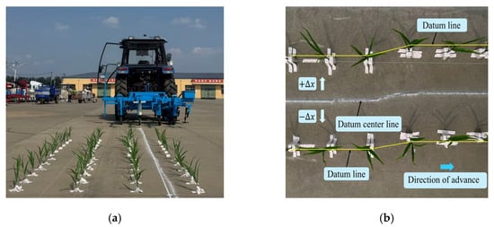
Figure 6.
(a) Schematic of the controlled-site experiment; (b) Sampling layout schematic.
To assess guidance accuracy, lateral positions were derived from the sand trace after the implement passed. Two parallel reference lines were laid along the outer sides of the two simulated rows, and their geometric centerline was taken as the reference centerline. Lateral deviation was defined with respect to the travel direction as positive to the left of the reference centerline and negative to the right. Sampling points were placed every 10 cm along the travel direction, and the opposing plants across the inter-row at each longitudinal position were treated as one sampling pair. At each sampling point, the perpendicular distance from the center of the actual trajectory to the reference centerline was measured, as shown in Figure 6b.
Three preset offsets were tested: (a) 5 cm, (b) 10 cm, and (c) 15 cm. Each offset was run at target operating speeds of 0.3 m/s, 0.4 m/s, and 0.5 m/s, with three repetitions at each speed. To comprehensively assess the accuracy and stability of the row-guidance system, we first define the lateral deviation as the lateral difference between the inter-row cultivator trajectory and the reference path at the sampling point. Because the target path may exhibit systematic drift during operation, we adopt a moving-reference evaluation: at each sampling position, the coordinate of the reference line at that location is taken as the reference, from which a signed deviation sequence of the inter-row cultivator trajectory is computed. Based on this sequence, we report the mean signed deviation, mean absolute error (MAE), root mean square error (RMSE), standard deviation (SD), percentile absolute error (E95), and maximum absolute error (Max ), and we also give the proportion of deviations falling within the ±15 cm and ±30 cm thresholds. This approach objectively captures the inter-row cultivator’s following ability and stability even when the reference line drifts as a whole.
To quantitatively evaluate row-guidance performance, we first define the lateral deviation (e) as the lateral offset of the inter-row cultivator trajectory with respect to the reference path:
where is the lateral deviation at the sampling point , in centimeters; is the lateral coordinate of the inter-row cultivator center at travel distance ; is the lateral coordinate of the reference path at the same longitudinal position; and is the longitudinal coordinate of sampling point along the travel direction. These quantities are used to compute the evaluation metrics.
2.3.2. Field Experiments
To verify the root-injury risk of the row-guided inter-row cultivator under field conditions, a maize trial was conducted at the Xiaotangshan National Precision Agriculture Research Demonstration Base in Changping District, Beijing, China. During seeding, an RTK receiver was mounted at the end of the planter crossbeam and aligned longitudinally with the metering unit; the planting-row trajectories were continuously recorded in a unified projected coordinate system, and the ground-projected RTK data were used to define reference line a (Figure 7, left). During inter-row cultivation, an RTK receiver of the same model was mounted at the geometric midpoint of the cultivator crossbeam to obtain the implement-center trajectory. Based on row spacing of 50 cm, this trajectory was shifted 25 cm to the left in the same coordinate system to form the target inter-row cultivation path, which was then fitted to the sowing trajectory so that cultivation was performed on the same crop row (Figure 7, right). The target operating speed was 0.5 m/s, and the actual operating speed, back-calculated from the RTK timestamps, was a constant 0.51 m/s. The plot parameters were as follows: row spacing of 50 cm, in-row plant spacing of 25 cm, and an effective single-row length of 30 m; buffer sections of 5 m at both ends of each row were reserved for acceleration and steady running [31], and data from these sections were excluded. To examine the influence of growth stage on risk, three sets of parameters were defined: the V2 to V3 stage with tillage depth 5 cm and root-system plan-view diameter 10 cm; the V4 to V5 stage with tillage depth 15 cm and root-system plan-view diameter 15 cm; and the V6 to V8 stage with tillage depth 10 cm and root-system plan-view diameter 22 cm. The root-system plan-view diameters for each growth stage were selected according to measurements of the lateral spread of maize roots under comparable cultivation conditions reported in [32,33]. For each growth stage, field inter-row cultivation tests were repeated three times, each covering a 30 m effective working section, and the duration of a single pass was calculated from the RTK trajectory timestamps, giving an average of 61 s. By keeping the seeding and cultivation trajectories coincident and using the same reference line a, spatial consistency between the two stages was ensured, allowing the root-damage rate to be quantitatively related to geometric deviation within a unified coordinate frame.
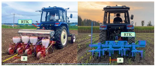
Figure 7.
Schematic of positional misalignment between sowing rows and the inter-row cultivation path. (where the two marked “a” denote the same line).
Meteorological data during the experiments were obtained from the automatic weather station at the experimental base. For each inter-row cultivation operation at the V2 to V3, V4 to V5, and V6 to V8 stages, daily mean air temperature, mean relative humidity, 10 min mean wind speed, and daily global solar radiation on the corresponding date were extracted, and the statistics are summarized in Table 1. The latitude–longitude data of the sowing and cultivation trajectories were fitted into geometric strips, and a strip representation consisting of the root-distribution zone, the cultivation zone, and the root-injury zone was constructed; the intersections of these strips were used as the basis for judging root injury. According to the root-system plan-view diameters at the V2 to V3, V4 to V5, and V6 to V8 stages reported in [32,33], a circular root-influence zone was defined for each plant by extending half of the corresponding diameter from the sowing-row centerline to either side, and this circle was regarded as the effective root-activity area of a single maize plant. After projecting the discrete RTK coordinates of the cultivation trajectory into the same coordinate system, the lateral position of each point was examined to determine whether it fell within the root-influence zone of the corresponding crop row; if it did, the cultivating blade at that location was considered to have entered the root zone and the point was counted as a root-injury point. Using the fixed spacing of the common coordinate axis together with the change in latitude between neighboring positions, the forward travel length associated with each location entering the root zone was calculated. The forward lengths of all points judged to have entered the root zone were then accumulated to obtain the total length inside the root zone. Using the same procedure over the entire operation yielded the total arc length of the cultivation trajectory. The root-damage rate was defined as the ratio of the total length inside the root zone to the total arc length of the cultivation trajectory, and the mean value of the three replicate operations was used to characterize the root-damage risk at each growth stage. It should be emphasized that only the overlapping segment between the cultivation band and the safety (root-distribution) zone contributes to the root-injury arc length; therefore, the root-damage rate actually reflects the proportion of this overlapping segment in the total cultivation trajectory length.

Table 1.
Meteorological data from the automatic weather station at the experimental base.
2.4. Statistical Analysis
The statistical metrics (MAE, RMSE, SD, and E95) were calculated from the original measurement data. For each cultivation pass, the lateral tracking error between the implement trajectory and the target row-guidance trajectory was obtained as an error sequence consisting of all discrete sampling points along the path. This error sequence was processed in Microsoft Excel (Version 2021). The mean absolute error (MAE) was computed as the arithmetic mean of the absolute errors, the root mean square error (RMSE) was obtained as the square root of the mean of the squared errors, the standard deviation (SD) was calculated from the error sequence, and the 95th percentile error (E95) was defined as the 95th percentile of the absolute error values. For each operating condition, the reported statistics are the averages over three replicate passes and are used to characterize the row-tracking performance under that condition.
In the root-damage risk analysis, the root-damage rate for a single pass was calculated as the ratio of the root-injury arc length (length of the trajectory segment overlapping the root-influence zone) to the total cultivation arc length, and the mean over three replicate passes was taken as the root-damage index for each growth stage. To assess whether the differences in mean root-damage rate among growth stages were statistically significant, one-way analysis of variance (ANOVA) was performed in Excel for the V2 to V3, V4 to V5, and V6 to V8 stages, with the significance level set at p < 0.001.
3. Results and Discussion
3.1. Controlled-Site Test
3.1.1. The Dynamic Response Test of the Row-Guidance Lateral-Shift Mechanism
Under unchanged control parameters, 20 datasets with target displacements from 1 to 20 cm in 1 cm increments were analyzed. As shown in Figure 8, the total time for the servo-electric cylinder to complete one commanded displacement increases approximately proportionally with displacement. To quantify this trend, a least squares linear regression was fit: each additional 1 cm of displacement increased the total time by 0.1426 s; moreover, as displacement approached zero, a fixed time of 0.025 s remained, attributable to start-up. The linear model achieved R2 0.997 (Coefficient of Determination); the deviation between regression predictions and measurements was at most 0.0010 s (mean 0.00011 s), indicating that a linear relation is sufficient and robust for the time–displacement relationship. Taking the reciprocal of the time-per-centimeter slope yields a reference speed of about 7.014 cm/s, interpretable as the asymptotic overall average speed for sufficiently large displacements.
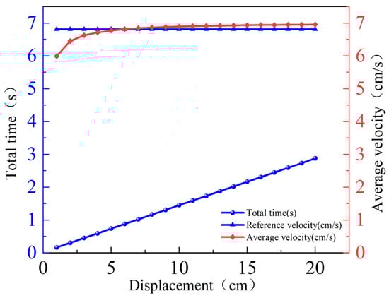
Figure 8.
Results of the lateral-shift mechanism response test.
The average speed shows the same pattern, increasing monotonically and gradually stabilizing: 5.99 cm/s at 1 cm, 6.78 cm/s at 5 cm, 6.90 cm/s at 10 cm, and 6.95 cm/s at 20 cm. Relative to the 7.014 cm/s reference speed, the deviation decreases from about 14.6% to <1%. This indicates that at small displacements, the fixed-time and the acceleration–deceleration phases occupy a larger fraction of the motion, lowering the average speed; as displacement increases, the constant-speed phase occupies a larger share, and the average speed approaches the reference. In sum, a stable calibration relationship between time and displacement was established and two quantities directly usable for subsequent control design were obtained: a fixed time of about 0.025 s and a reference speed of about 7.014 cm/s. Accordingly, the minimum look-ahead compensation time threshold should not be lower than this fixed time plus the delays of recognition and communication, and the initial per-cycle displacement limit can be computed from the reference speed and the control period and then checked with a conservative factor.
3.1.2. The Row-Guidance Accuracy Test at Different Speeds
Across the three preset offset magnitudes, the inter-row cultivator trajectory followed the reference centerline. As speed increased, the lateral-shift servo-electric cylinder initiated motion in advance of the target point to ensure on-time arrival at the commanded offset.
As shown in Figure 9, for a 5 cm preset offset, the inter-row cultivator trajectories at 0.31 m/s, 0.42 m/s, and 0.51 m/s nearly coincided with the reference centerline, with only slight lateral adjustment near the offset initiation point at approximately cm. The three curves nearly overlap, indicating rapid correction and high trajectory stability under small-offset conditions.
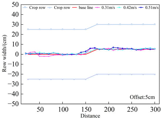
Figure 9.
Row-guidance trajectories at different speeds (5 cm offset).
As shown in Figure 10, with a 10 cm preset offset the correction exhibited a noticeable lag: at the offset initiation point, the trajectory deviated from the reference centerline, then gradually returned toward it over the next 50–80 cm of travel. Compared with the 5 cm case, oscillations were more pronounced; at 0.51 m/s the correction amplitude was slightly larger than at the lower speeds, indicating a slight amplification of the correction dynamics with increasing speed.
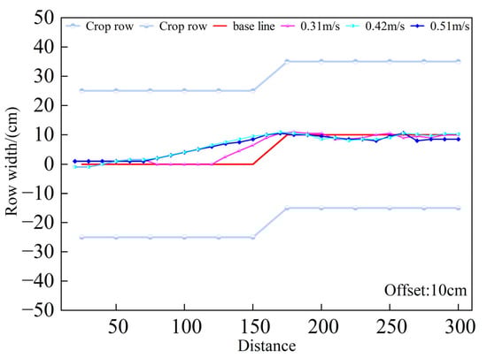
Figure 10.
Row-guidance trajectories at different speeds (10 cm offset).
As shown in Figure 11, for a 15 cm preset offset, both the trajectory deviation and the distance required for correction increased markedly. Across the three speeds, the trajectories exhibited larger instantaneous lateral excursions and required a longer correction distance to realign with the reference centerline. Oscillation amplitude was greatest under this condition, indicating reduced stability at large offsets. Nevertheless, the trajectories remained qualitatively consistent across speeds, with no loss of control or severe departure from the inter-row corridor.
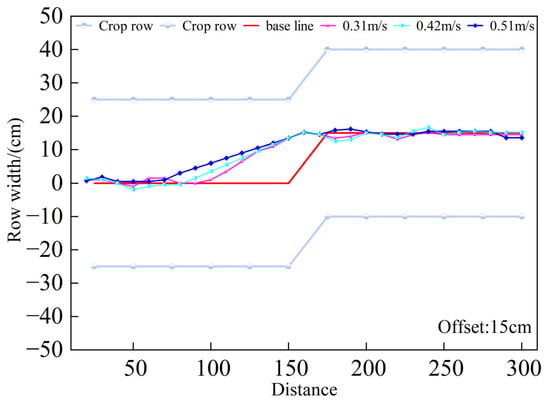
Figure 11.
Row-guidance trajectories at different speeds (15 cm offset).
Overall, increasing the imposed offset led to larger instantaneous deviation, longer correction distance, and more pronounced oscillations, whereas within 0.31–0.51 m/s the effect of speed on trajectory shape was minor and became apparent only at large offsets. This indicates that under low-speed operation the system maintains stable tracking, but larger offsets substantially increase the difficulty of correction.
Table 2 quantifies these patterns. With a 5 cm preset offset, MAE was 0.76–1.03 cm, RMSE was 0.94–1.44 cm, the 95th percentile absolute error (E95) did not exceed 3.1 cm, and the maximum absolute error was 4.0 cm, indicating high accuracy under small-offset conditions and very small deviations for most points. At a 10 cm offset, errors increased markedly: RMSE reached 1.07–2.31 cm, E95 rose to 5.3 cm, and the maximum absolute error reached 6.5 cm, reflecting longer correction distances and larger oscillations. At a 15 cm offset, errors increased further, with RMSE up to 3.13 cm, E95 7.5 cm, and maximum absolute error 9.0 cm, roughly doubling or more compared with the 5 cm condition. In contrast, for a fixed offset the effect of speed was small: across the three speeds, differences in MAE and RMSE were < 0.5 cm, and SD remained 0.8–2.8 cm, indicating strong robustness within the low-speed range (0.31–0.51 m/s). Thus, offset is the primary determinant of row-guidance accuracy, whereas speed plays a limited role in this range. Mechanistically, the lateral-shift servo-electric cylinder has a physical speed limit: larger offsets require more time to reach the target position, so the controller must trigger earlier to ensure arrival before the crop row. If the lead time is insufficient, instantaneous deviation and correction distance increase—consistent with the trajectory plots and error statistics. Even under the most adverse 15 cm offset, 100% of deviations fell within ±15 cm, meeting agronomic requirements. This shows that, with appropriate look-ahead compensation, the proposed row-guidance control method delivers stable, reliable operation despite actuator speed limits.
Table 2.
Row-guidance error statistics under different speeds and offsets.
3.2. Field Trial
At the V2 to V3 stage, maize roots were mainly distributed in the shallow soil on both sides of the row, with a narrow lateral spread and an overall banded, concentrated pattern (Figure 12a). During this stage, the inter-row cultivator’s trajectory remained near the inter-row centerline and was stable, theoretically within the root-zone safety band. However, the enlarged view (Figure 12b) shows that, due to small deviations in machine motion and surface undulations, portions of the cultivation trajectory already overlapped the root-zone band; the intersection arc lengths for row 5 and row 7 were 13.5 cm and 26 cm, respectively. These results indicate that even at an early growth stage, roots may locally extend into the inter-row corridor, so minor lateral offsets of the cultivation trajectory can still pose a risk of cutting marginal roots.
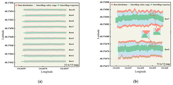
Figure 12.
Inter-row cultivation trajectory and root-zone distribution at the V2 to V3 stage: (a) overview; (b) root-injury detail.
At the V4 to V5 stage, maize roots expanded markedly from both sides into the inter-row corridor, widening the root-zone band and sharply narrowing the root-zone safety band (Figure 13a). The implement trajectory generally remained near the inter-row centerline, but root expansion combined with small lateral offsets produced clear spatial intersections in some rows; the intersection arc lengths were 330.6 cm and 141 cm, respectively (Figure 13b).
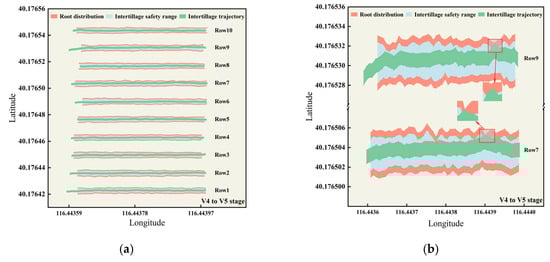
Figure 13.
Inter-row cultivation trajectory and root-zone distribution at the V4 to V5 stage: (a) overview; (b) root-injury detail.
These results indicate a reduced safety margin at this stage: spatial interference between the root zone and the cultivation band intensifies, and the risk of root injury increases. Compared with the V2 to V3 stage, segments that were previously separated became intersecting, consistent with the field-measured root-injury rate rising to 1.46%. Although cultivation remains feasible at the V4 to V5 stage, tighter path control is required, and operating parameters should be adjusted in response to root-zone expansion—for example, narrowing the blade working width and increasing the safety clearance—to achieve efficient, low-injury operation.
At the V6 to V8 stage, maize roots laterally spanned the inter-row corridor, causing a substantial reduction in the width of the root-zone safety band (Figure 14a). The cultivation trajectory exhibited strong, continuous overlap with the root zone, with a local maximum intersection arc length of ~562.4 cm. Quantitatively, the cumulative injury arc length totaled ~3106 cm, and the root-injury rate rose to 9.61%, an ~6.6-fold increase over the 1.46% at the V4 to V5 stage (Figure 14b). Although coverage increased to 57%, the benefit–risk trade-off deteriorated markedly, indicating that a conventional strategy assuming fixed row spacing and constant tillage depth is no longer suitable at this stage. Accordingly, the V6 to V8 stage marks the spatial closure of the cultivation window. If cultivation is still required, shallow, low-disturbance passes with depth-limiting and variable-width tools, combined with root-zone avoidance and adaptive trajectory control, are recommended to achieve low-intrusion, low-injury, root-preserving operation.
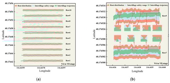
Figure 14.
Inter-row cultivation trajectory and root-zone distribution at the V6 to V8 stage: (a) overview; (b) root-injury detail.
The field results show that as maize development progressed, lateral root expansion intensified and continuously compressed the root-zone safety band, leading to concurrent increases in both the injury arc length and the root-injury rate: as shown in Table 3, at the V2 to V3 stage, the injury rate was 0.12% with ~40% coverage, representing a root-preserving regime; at the V4 to V5 stage, the injury rate was 1.46% with ~45% coverage, achieving the best balance between safety and coverage; at the V6 to V8 stage, the injury rate was 9.61% with ~57% coverage, and operational risk increased markedly. Based on the data from three replicate passes, as shown in Table 4, the results of one-way analysis of variance (ANOVA) showed that growth stage had a highly significant effect on root-damage rate (p < 0.001); the mean root-damage rate at the V6 to V8 stage was significantly higher than at the V2 to V3 and V4 to V5 stages, whereas the difference between the V2 to V3 and V4 to V5 stages was not statistically significant. Beyond temporal effects, local row-directional skew interfered with vision-based row guidance, causing the cultivation path to exhibit mild-to-moderate incursions into the sowing trajectory in several segments, with the most evident recurrence at the same segment of rows 7 and 9.
Table 3.
Statistics of root injury and coverage across leaf stages.
Table 4.
One-way ANOVA of root-damage rate among maize growth stages.
3.3. Discussion
Within a unified coordinate framework, this study registers the row-guidance trajectories, root distribution, and cultivation outcomes. The results show that as the growth stage advances, the inter-row safety belt continuously shrinks and tends to close; even when the mean absolute row-guidance error is on the order of 1 cm, multiple local and continuous overlaps still occur in the middle and late stages, causing the injury arc length and root-damage rate to increase in step with the lateral expansion of the root system. The field results can be summarized in three stages: at the V2 to V3 stage, root damage remains at a very low level while weed control can be maintained; at the V4 to V5 stage, a compromise is achieved between safety and coverage; at the V6 to V8 stage, pronounced accumulation of root damage appears under the same tracking accuracy. This indicates that cultivation timing is the primary risk-control variable under given row spacing and operational accuracy, whereas geometric row-guidance error alone cannot fully represent operational safety. Repeated overlaps at headlands, outer rows, and segments with abrupt changes in row direction suggest that sowing-row skew and micro-topographic undulations amplify local risk, but the overall trend is still dominated by the temporal lateral expansion of the root zone. Taken together, the spatial-registration evidence indicates that early cultivation provides a larger safety margin; the V4 to V5 stage is the recommended window that balances root safety and weed-control coverage, and if cultivation is required at the V6 to V8 stage for management reasons, shallow tillage, reduced working width, and moderate speed reduction should be adopted to lower the probability of entering the root zone while retaining the necessary coverage.
Compared with existing camera-guided hoeing studies [34], this work introduces a quantitative evaluation of root damage under a similar level of row-guidance accuracy. Previous studies have achieved high inter-row operational efficiency and stable geometric accuracy at low to medium speeds, but system performance has mostly been evaluated by indicators such as row-center deviation, and comparable root-damage data are rarely reported. Research in near-crop spaces has shown that, for crops such as tomato and lettuce, geometric detection and real-time control of in-row tools can realize deterministic trajectories within a narrow safety belt, whereas higher speeds or unstable implement attitude tend to amplify lateral deviation and increase the risk of crop interference [35]. In contrast, the present study uses electric lateral shifting and delay compensation to keep row-guidance error within less than a 1 cm range and, at this accuracy level, achieves a combined performance of low root damage and relatively high coverage. Thus, the performance evaluation is extended from geometric accuracy to root-risk indicators, providing experimental evidence for determining maize cultivation windows under root-zone safety constraints.
From an engineering perspective, the system takes the sowing RTK trajectory as the primary reference, uses visual detection for auxiliary correction, and combines delay compensation with servo-electric cylinder control so that the row-position information acquired during sowing can be used directly for row guidance during cultivation. This maintains consistency between sowing and cultivation tracks in fields with terrain undulations and row-direction deviations. Field results show that row-guidance error increases with forward speed, while the effective width of the safety belt is correspondingly reduced and local risk increases [36]; related studies have likewise indicated that tight coupling among perception, positioning, and actuation is essential for maintaining trajectory consistency under continuous operation [37]. Therefore, combining low-delay control and trajectory-consistency design with parameter adaptation offers promising engineering potential for wider deployment of such systems [38].
4. Conclusions
In this study, we developed a vision-based row-guidance inter-row cultivator for maize, integrating a deep learning row-line detection module with a lateral-shift servo-electric cylinder actuator, together with a root-injury quantification method based on a unified coordinate frame and arc-length integration. Controlled-site offset tests showed stable correction at offsets of 5, 10, and 15 cm and speeds of 0.31, 0.42, and 0.51 m/s. Under low-speed, small-offset conditions, the MAE was 0.76–1.03 cm, for instance, at a 5 cm initial offset and 0.51 m/s, and the lateral deviation was 0.76 ± 0.86 cm. Across these conditions, the 95th percentile absolute error was 1.5–3.1 cm, and the maximum absolute error was 3.5–4.0 cm; with a 15 cm offset at 0.51 m/s, the tail of the error distribution increased markedly (MAE = 1.94 ± 2.76 cm; 95th percentile absolute error ≈ 7.5 cm; maximum absolute error 9.0 cm). These results indicate high accuracy and robustness at small offsets; offset dominates the error distribution and correction distance, while speed mainly amplifies tail risk when combined with larger offsets. Compared with existing row-guided cultivators that mainly rely on hydraulic actuation or evaluate performance only in terms of geometric deviation, the proposed system integrates electric lateral shifting with delay compensation to maintain centimeter-level row-guidance accuracy while introducing injury arc-based risk quantification and cultivation-window determination, thereby providing an engineering-feasible route for safe mechanical inter-row cultivation of maize at the seedling stage. However, these quantitative thresholds were derived from tests at a single forward speed of 0.51 m/s in one soil type and implement configuration and should therefore be regarded as indicative rather than universally applicable. Future work will refine force and attitude feedback and injury risk-based closed-loop control, will validate the system’s adaptability to higher speeds, other row crops, and different cultivator geometries, and will investigate integrating wireless communication and remote monitoring to support higher levels of automation.
In field operation at 0.51 m/s, the root-injury rate and coverage were 0.12% and 40% at the V2 to V3 stage, 1.46% and 45% at the V4 to V5 stage, and 9.61% and 57% at the V6 to V8 stage. With speed and row-guidance accuracy held constant, root injury increased with plant age as lateral root growth progressively compressed the root-zone safety margin, which is the primary driver of operational risk. Mechanically, larger offsets or higher speeds increase demands on stroke and rate, raise the correction frequency, and elevate the risks of overshoot and local overlap; working width, penetration depth, and tool flexibility jointly determine the disturbance footprint, so adopting narrow working width, depth-limiting, and flexible tools helps reduce root-zone impact. On the control side, delay compensation matched to operating conditions and an adequate actuator response rate are essential to avoid correction lag and error accumulation. Within the scope of the present experiments with a forward speed of 0.51 m/s, a single soil condition, and the tested implement–field combination, these results indicate that inter-row cultivation should preferably be scheduled during the V4 to V5 stage window. If mid- or late-stage cultivation is unavoidable under similar conditions, the adoption of shallow, depth-limited, narrow-width flexible tools coupled with risk-segment identification and adaptive trajectory control technology can achieve a dynamic balance between weeding coverage and root system safety. However, their effectiveness under other soil types, climatic conditions, and crop architectures requires further verification.
Author Contributions
Conceptualization, H.Y. and X.Z.; methodology, H.Y. and C.L.; software, Z.Y.; data curation, H.L., Z.Y. and C.Z.; formal analysis, X.Z. and C.L.; validation, H.L. and X.Z.; writing—original draft preparation, H.Y.; writing—review and editing, L.W. and C.Z.; funding acquisition, C.L. and L.W. All authors have read and agreed to the published version of the manuscript.
Funding
This research was funded by the National Natural Science Foundation of China (Grant No. 32201647), the Special Program for Innovation Capacity Building of Beijing Academy of Agriculture and Forestry Sciences (Grant No. 02Z0009143), the Basic Scientific Research Project of Liaoning Provincial Department of Education (Grant No. LJ222510157002), and the Key Research and Development Project of Liaoning Province (Grant No. 2024020988-JH2/1025).
Data Availability Statement
The data used in this study are available from the corresponding author upon reasonable request.
Conflicts of Interest
The authors declare that they have no competing interests.
Abbreviations
The following abbreviations are used in this manuscript:
| FoV | Field of View |
| MAE | Mean Absolute Error |
| RMSE | Root Mean Square Error |
| SD | Standard Deviation |
| R2 | Coefficient of Determination |
| RTK | Real-Time Kinematic |
| USB | Universal Serial Bus |
| CAN | Controller Area Network |
| USB-CAN | USB-to-CAN Interface |
| ID | Identifier |
| RPM | Revolutions Per Minute |
| YOLOv8s | You Only Look Once, version 8, small |
Appendix A
Table A1.
Comparison of mechanical inter-row cultivation with other non-chemical weeding technologies.
Table A1.
Comparison of mechanical inter-row cultivation with other non-chemical weeding technologies.
| Technique (Non-Chemical) | Principle/Typical Targets | Main Advantages (Non-Chemical Benefits) | Main Limitations/Challenges |
|---|---|---|---|
| Mechanical inter-row cultivation (this study) | Steel sweeps or hoes cut, uproot, or bury weeds between rows; shallow loosening of inter-row soil; typically combined with guidance system | No herbicides; high field capacity at practical travel speeds; can be mounted on standard tractors; directly integrates soil loosening with weed removal; robust under a wide range of field conditions [6] | Risk of crop or root injury if guidance accuracy or timing is poor; less effective on in-row weeds; performance sensitive to soil moisture, clods, and surface residues; requires careful matching of tools to crop stage [6] |
| Laser/electric weeding | Vision system detects individual weeds close to the crop, followed by focused laser beam or electric discharge to thermally destroy the meristem [4] | Very high spatial selectivity; minimal soil disturbance; suitable for intra-row weeds that are difficult to reach mechanically; no chemical residues [4,6] | High capital and maintenance cost; narrow effective working width and relatively low forward speed; high energy demand; strict safety and eye-protection requirements; currently more suited to small areas or high-value crops [4,6] |
| Flame/thermal weeding (incl. hot water/steam) | Propane flame, hot gases, or hot water/steam rapidly heat seedlings and denature proteins, causing desiccation [5] | Fully herbicide-free; can be effective against many small annual broadleaf weeds; applicable in organic systems; little mechanical disturbance of soil structure [5,6] | High fuel consumption and associated CO2 emissions; risk of fire and crop scorching; efficacy strongly affected by wind and rainfall; often requires repeated passes to control regrowth and perennial weeds; operator safety must be ensured [5] |
| Mulching (organic, plastic, or biodegradable) | Straw, compost, plastic film, or biodegradable mulch forms a physical barrier at the soil surface, blocking light and physically hindering weed emergence [5,6] | Strong suppression of new weed flushes; improves soil moisture retention and can buffer soil temperature; may substantially reduce herbicide demand in some systems [5,6] | Cost and availability of mulch materials; plastic films require removal or recycling and may leave residues; mulches can interfere with mechanical operations and may increase certain pests (e.g., slugs or rodents) under humid conditions [5,6] |
| Crop-timing strategies (early sowing, transplanting, stale seedbed, etc.) | Adjust sowing date or use transplants so that the crop emerges and closes canopy before the main weed flush; stale seedbed encourages weeds to germinate and be destroyed before planting [6] | Very low direct input cost; can considerably reduce early-season weed pressure and herbicide use; compatible with both mechanical and chemical strategies; may contribute to more stable yields [6] | Strongly climate- and site-dependent; planting too early can result in poor crop establishment; stale seedbeds require additional passes and machinery; does not directly remove later weed flushes and therefore usually needs to be combined with other control methods [6] |
References
- Zhang, Z.; Li, R.; Zhao, C.; Qiang, S. Reduction in weed infestation through integrated depletion of the weed seed bank in a rice-wheat cropping system. Agron. Sustain. Dev. 2021, 41, 10. [Google Scholar] [CrossRef]
- Parven, A.; Meftaul, I.M.; Venkateswarlu, K.; Megharaj, M. Herbicides in modern sustainable agriculture: Environmental fate, ecological implications, and human health concerns. Int. J. Environ. Sci. Technol. 2025, 22, 1181–1202. [Google Scholar] [CrossRef]
- European Innovation Partnership for Agricultural Productivity and Sustainability (EIP-AGRI). Inspirational Ideas: Weed Control Without Chemicals. Available online: https://ec.europa.eu/eip/agriculture/en/news/inspirational-ideas-weed-control-without-chemicals.html (accessed on 9 October 2025).
- Mwitta, C.; Rains, G.C.; Prostko, E.P. Autonomous diode laser weeding mobile robot in cotton field using deep learning, visual servoing and finite state machine. Front. Agron. 2024, 6, 1388452. [Google Scholar] [CrossRef]
- Upadhyay, A.; Singh, K.P.; Jhala, K.B.; Kumar, M.; Salem, A. Non-chemical weed management: Harnessing flame weeding for effective weed control. Heliyon 2024, 10, e32776. [Google Scholar] [CrossRef]
- Adeleke, A.A. Technological advancements in cotton agronomy: A review and prospects. Technol. Agron. 2024, 4, e008. [Google Scholar] [CrossRef]
- Rao, A.N.; Singh, R.G.; Mahajan, G.; Wani, S.P. Weed research issues, challenges, and opportunities in India. Crop Prot. 2020, 134, 104451. [Google Scholar] [CrossRef]
- Heisel, T.; Andreasen, C.; Christensen, S. Sugarbeet yield response to competition from Sinapis arvensis or Lolium perenne growing at three different distances from the beet and removed at various times during early growth. Weed Res. 2002, 42, 406–413. [Google Scholar] [CrossRef]
- Xu, H.; Li, T.; Hou, X. Key technologies and research progress of intelligent weeding robots. Weed Sci. 2025, 73, e25. [Google Scholar] [CrossRef]
- Machleb, J.; Peteinatos, G.G.; Kollenda, B.L.; Andújar, D.; Gerhards, R. Sensor-based mechanical weed control: Present state and prospects. Comput. Electron. Agric. 2020, 176, 105638. [Google Scholar] [CrossRef]
- Chen, Z.; Zhang, C.; Li, N.; Sun, Z.; Li, W.; Zhang, B. Study review and analysis of high performance intra-row weeding robot. Trans. Chin. Soc. Agric. Eng. 2015, 31, 1–8. [Google Scholar] [CrossRef]
- Bloomer, D.J.; Harrington, K.C.; Ghanizadeh, H.; James, T.K. Robots and shocks: Emerging non-herbicide weed control options for vegetable and arable cropping. N. Z. J. Agric. Res. 2024, 67, 81–103. [Google Scholar] [CrossRef]
- Cordill, C.; Grift, T.E. Design and testing of an intra-row mechanical weeding machine for corn. Biosyst. Eng. 2011, 110, 247–252. [Google Scholar] [CrossRef]
- Jiang, B.; Zhang, J.-L.; Su, W.-H.; Hu, R. A SPH-YOLOv5x-Based Automatic System for Intra-Row Weed Control in Lettuce. Agronomy 2023, 13, 2915. [Google Scholar] [CrossRef]
- Pérez-Ruiz, M.; Slaughter, D.C.; Gliever, C.J.; Upadhyaya, S.K. Automatic GPS-based intra-row weed knife control system for transplanted row crops. Comput. Electron. Agric. 2012, 80, 41–49. [Google Scholar] [CrossRef]
- Pérez-Ruiz, M.; Slaughter, D.C.; Fathallah, F.A.; Gliever, C.J.; Miller, B.J. Co-robotic intra-row weed control system. Biosyst. Eng. 2014, 126, 45–55. [Google Scholar] [CrossRef]
- Zheng, S.; Zhao, X.; Fu, H.; Tan, H.; Zhai, C.; Chen, L. Design and Experimental Evaluation of a Smart Intra-Row Weed Control System for Open-Field Cabbage. Agronomy 2025, 15, 112. [Google Scholar] [CrossRef]
- Li, Y.; Qu, Y.; Fang, Y.; Yang, J.; Lu, Y. Design and Experiment of Autonomous Shield-Cutting End-Effector for Dual-Zone Maize Field Weeding. Agriculture 2025, 15, 1549. [Google Scholar] [CrossRef]
- Zhao, C.-T.; Wang, R.-F.; Tu, Y.-H.; Pang, X.-X.; Su, W.-H. Automatic Lettuce Weed Detection and Classification Based on Optimized Convolutional Neural Networks for Robotic Weed Control. Agronomy 2024, 14, 2838. [Google Scholar] [CrossRef]
- FarmDroid FD20—FarmDroid. Available online: https://farmdroid.com/products/farmdroid-fd20/ (accessed on 9 November 2025).
- Automatic Weeder—Ferrari Growtech REMOWEED and SCORPION. Available online: https://ferrarigrowtech.com/en/automated-weeders/28-remoweed.html (accessed on 9 November 2025).
- EC–Weeder LEMKEN. Available online: https://lemken.com/en-en/agricultural-machines/cropcare/weed-control/mechanical-weed-control/ec-weeder (accessed on 9 November 2025).
- Nørremark, M.; Griepentrog, H.W.; Nielsen, J.; Søgaard, H.T. The Development and Assessment of the Accuracy of an Autonomous GPS-Based System for Intra-Row Mechanical Weed Control in Row Crops. Biosyst. Eng. 2008, 101, 396–410. [Google Scholar] [CrossRef]
- Nørremark, M.; Griepentrog, H.W.; Nielsen, J.; Søgaard, H.T. Evaluation of an Autonomous GPS-Based System for Intra-Row Weed Control by Assessing the Tilled Area. Precis. Agric. 2012, 13, 149–162. [Google Scholar] [CrossRef]
- Liu, H.; Wang, Y.; Zhai, C.; Wu, H.; Fu, H.; Feng, H.; Zhao, X. DWG-YOLOv8: A Lightweight Recognition Method for Broccoli in Multi-Scene Field Environments Based on Improved YOLOv8s. Agronomy 2025, 15, 2361. [Google Scholar] [CrossRef]
- Lyu, Z.; Lu, A.; Ma, Y. Improved YOLOv8-Seg Based on Multiscale Feature Fusion and Deformable Convolution for Weed Precision Segmentation. Appl. Sci. 2024, 14, 5002. [Google Scholar] [CrossRef]
- Khan, M.N.; Rahi, A.; Rajendran, V.P.; Al Hasan, M.; Anwar, S. Real-time crop row detection using computer vision—Application in agricultural robots. Front. Artif. Intell. 2024, 7, 1435686. [Google Scholar] [CrossRef] [PubMed]
- Ota, K.; Kasahara, J.Y.L.; Yamashita, A.; Asama, H. Weed and crop detection by combining crop row detection and k-means clustering in weed-infested fields. In Proceedings of the 2022 IEEE/SICE International Symposium on System Integration (SII), Narvik, Norway, 9–12 January 2022; pp. 985–990. [Google Scholar] [CrossRef]
- Liu, Y.; Guo, Y.; Wang, X.; Yang, Y.; Zhang, J.; An, D.; Han, H.; Zhang, S.; Bai, T. Crop Root Rows Detection Based on Crop Canopy Image. Agriculture 2024, 14, 969. [Google Scholar] [CrossRef]
- Wang, C.; Ding, Y.; Cui, K.; Li, J.; Xu, Q.; Mei, J. A Perspective Distortion Correction Method for Planar Imaging Based on Homography Mapping. Sensors 2025, 25, 1891. [Google Scholar] [CrossRef]
- Zheng, K.; Zhao, X.; Han, C.; He, Y.; Zhai, C.; Zhao, C. Design and Experiment of an Automatic Row-Oriented Spraying System Based on Machine Vision for Early-Stage Maize Corps. Agriculture 2023, 13, 691. [Google Scholar] [CrossRef]
- Quan, L.; Zhang, J.; Jiang, W.; Li, H.; Yang, C.; Zhang, X. Development and experiment of an intra-row weeding robot system based on protection of maize root system. Trans. Chin. Soc. Agric. Mach. 2021, 52, 115–123. [Google Scholar] [CrossRef]
- Chen, Y.; Yang, Q.; Wang, J.; Miao, Z.; Zhao, W.; Jia, X.; Dong, P.; Wang, Q. Effects of Intercropping on Root Distribution, Nutrient Accumulation and Yield of Maize with Different Root Architecture. J. Nucl. Agric. Sci. 2023, 37, 594–605. [Google Scholar] [CrossRef]
- Gerhards, R.; Kollenda, B.L.; Machleb, J.; Möller, K.; Butz, A.; Reiser, D.; Griepentrog, H.-W. Camera-guided weed hoeing in winter cereals with narrow row distance. Gesunde Pflanz. 2020, 72, 403–411. [Google Scholar] [CrossRef]
- Raja, R.; Nguyen, T.T.; Slaughter, D.C.; Fennimore, S.A. Real-time robotic weed knife control system for tomato and lettuce based on geometric appearance of plant labels. Biosyst. Eng. 2020, 194, 152–164. [Google Scholar] [CrossRef]
- Dallas, J.; Jain, K.; Dong, Z.; Sapronov, L.; Cole, M.P.; Jayakumar, P.; Ersal, T. Online terrain estimation for autonomous vehicles on deformable terrains. J. Terramech. 2020, 91, 11–22. [Google Scholar] [CrossRef]
- Visentin, F.; Cremasco, S.; Sozzi, M.; Signorini, L.; Signorini, M.; Marinello, F.; Muradore, R. A mixed-autonomous robotic platform for intra-row and inter-row weed removal for precision agriculture. Comput. Electron. Agric. 2023, 214, 108270. [Google Scholar] [CrossRef]
- Upadhyay, A.; Zhang, Y.; Koparan, C.; Rai, N.; Howatt, K.; Bajwa, S.; Sun, X. Advances in ground robotic technologies for site-specific weed management in precision agriculture: A review. Comput. Electron. Agric. 2024, 225, 109363. [Google Scholar] [CrossRef]
Disclaimer/Publisher’s Note: The statements, opinions and data contained in all publications are solely those of the individual author(s) and contributor(s) and not of MDPI and/or the editor(s). MDPI and/or the editor(s) disclaim responsibility for any injury to people or property resulting from any ideas, methods, instructions or products referred to in the content. |
© 2025 by the authors. Licensee MDPI, Basel, Switzerland. This article is an open access article distributed under the terms and conditions of the Creative Commons Attribution (CC BY) license (https://creativecommons.org/licenses/by/4.0/).