You are currently viewing a new version of our website. To view the old version click .
Polymers
  • Article
  • Open Access

10 November 2025

Enabling Industrial Re-Use of Large-Format Additive Manufacturing Molding and Tooling

,
,
,
,
,
,
,
,
and
1
Oak Ridge National Laboratory, Manufacturing Science Division, 1 Bethel Valley Rd., Oak Ridge, TN 37830, USA
2
Department of Mechanical & Aerospace Engineering, University of Tennessee Knoxville, 400 W. Summit Hill Dr., Knoxville, TN 37902, USA
3
Airtech International Inc., 5700 Skylab Road, Huntington Beach, CA 92647, USA
4
Department of Materials Science & Engineering, University of Tennessee Knoxville, 400 W. Summit Hill Dr., Knoxville, TN 37902, USA
Polymers2025, 17(22), 2981;https://doi.org/10.3390/polym17222981 
(registering DOI)
This article belongs to the Special Issue Additive Manufacturing of Polymer Based Materials

Abstract

Large-format additive manufacturing (LFAM) is an enabling manufacturing technology capable of producing large parts with highly complex geometries for a wide variety of applications, including automotive, infrastructure/construction, and aerospace mold and tooling. In the past decade, the LFAM industry has seen widespread use of bio-based, glass, and/or carbon fiber reinforced thermoplastic composites which, when printed, serve as a lower-cost alternative to metallic parts. One of the highest-volume materials utilized by the industry is carbon fiber (CF)-filled polycarbonate (PC), which in out-of-autoclave applications can achieve comparable mechanical performance to metal at a significantly lower cost. Previous work has shown that if this material is recovered at various points throughout the manufacturing process for both the lab and pilot scale, it can be mechanically recycled with minimal impacts on the functional performance and printability of the material while significantly reducing the feedstock costs. End-of-life (EOL) CF-PC components were processed through industrial shredding, melt compounding, and LFAM equipment, followed by evaluation of the second-life material properties. Experimental assessments included quantitative analysis of fiber length attrition, polymer molecular weight degradation using gel permeation chromatography (GPC), density changes via pycnometry, thermal performance using dynamic mechanical analysis (DMA), and mechanical performance (tensile properties) in both the X- and Z-directions. Results demonstrated a 24.6% reduction in average fiber length compared to virgin prints, accompanied by a 21% decrease in X-direction tensile strength and a 39% reduction in tensile modulus. Despite these reductions, Z-direction tensile modulus improved by 4%, density increased by 6.8%, and heat deflection temperature (HDT) under high stress retained over 97% of its original value. These findings underscore the potential for integrating mechanically recycled CF-PC into industrial LFAM applications while highlighting the need for technological innovations to mitigate fiber degradation and enhance material performance for broader adoption. This critical step toward circular material practices in LFAM offers a pathway to reducing feedstock costs and environmental impact while maintaining functional performance in industrial applications.

1. Introduction

Fiber-reinforced polymeric composites combine structural fibers (e.g., carbon or glass fiber) with polymer resin, delivering performance levels of commercial metals, but are more easily manufacturable and come at a fraction of the cost and density []. Because of this, they have become widely adopted as lightweight, high-performance alternatives to metals in several industries, including aerospace, transportation, medical, sporting goods, and energy generation [,,,,]. Currently, the majority (~60%) of the resins used for composites are thermoset materials, such as epoxy and vinyl ester [,]. While effective, these materials are difficult to recycle or re-shape at the end of their life cycle and are typically landfilled at rates > 90% [,,,]. This challenge has led to increasing interest in thermoplastic materials, such as polycarbonate (PC), which offer the potential for recycling, particularly in non- or semi-structural applications []. Due to its glass transition temperature (Tg) (~150 °C) and stiffness, carbon fiber (CF)-filled PC (CF-PC) is commonly used for the transportation and/or aerospace industry for molds and tools that need to cure at elevated temperatures []. However, thermoplastic options like CF-PC come at a significantly higher price point—about 35 USD/kg—compared to thermoset composites, at 1–3 USD/kg [,]. This price point poses a major barrier to broader industrial adoption of CF-PC composites; however, this material has seen significant growth as a feedstock for large-format additive manufacturing (LFAM), where its high strength and low coefficient of thermal expansion are significant advantages.
LFAM is an industrially available technology that is uniquely capable of producing complex geometries more than 90 m3 in volume without the use of jigs or tools [,]. LFAM has been transformative for several industries, including aerospace, automotive, and even construction, generating previously un-manufacturable products, as well as rapid prototyping tools/molds [,]. When considering lower-cost feedstocks like plastics, scaling up additive manufacturing to these volumes necessitates the use of fiber-reinforced thermoplastics that can withstand the thermal stresses experienced within the printed material volume to prevent print warpage [,]. Such material systems include CF-filled acrylonitrile butadiene styrene (ABS), poly(ethyleneimine), polyether ether ketone, and PC, among others [,,]. Because this technology does not require a tool or jig, LFAM is largely considered less wasteful than other manufacturing technologies []. However, there are multiple points throughout the process where waste can be generated, especially at larger build volumes []. Notable points for waste generation include while (1) purging between printed layers to achieve desired layer times, (2) generating failed prints that cannot be recovered, (3) machining flakes when the parts are milled to their final shape, and (4) at end-of-life (EOL) of the printed part. Successful prints can have functional lifetimes as short as a single use or as many as a few hundred cycles, after which these molds are typically landfilled [,,,]. This landfilling is largely due to a lack of understanding around how these materials would perform in their second life if recycled, complex reverse logistics associated with recycling, increased propensity for cross-contamination from bolts/screws/coatings, and perceived high costs of recycling as compared to virgin material production [].
These LFAM materials can be recycled, however, using several techniques, including mechanical, chemical, thermal, pressure-based, and even enzymatic technologies [,,,,,,,,,]. Of these available technologies, mechanical recycling has been shown to generate new feedstocks at significantly reduced cost and energy as compared to other technologies while still meeting product specifications [,,]. For mechanical recycling, which depends upon the use of a uni-material stream, materials are shredded and granulated, then either directly printed using LFAM or melt-compounded and re-pelletized into feedstocks for LFAM [,]. Previous lab-scale research has shown that recycling CF-ABS can result in materials that meet performance specifications at a 73% cost saving over incumbent pristine feedstocks [,]. However, some have explored the direct re-use of composite granulate in LFAM applications, demonstrating that a loss of fiber content, rather than fiber length degradation, could contribute to a reduction in composite properties []. In contrast, others have explored recycling by melt compounding and re-pelletizing machining scrap but found the reduction in fiber length from milling significantly reduced properties in the re-manufactured parts []. People have explored degradation pathways for bio-sourced feedstocks, such as poly (lactic acid) (PLA), in LFAM over multiple cycles and observed molecular weight reduction caused by thermomechanical, oxidative degradation []. When PLA is used in composites such as those with wood flour fillers, minimal degradation is observed in functional performance with recycling [,]. Others have explored the use of non-mechanical methods of recycling, including chemical recycling. However, although there is growing academic research on the degradation pathways for CF-ABS, to the best of the authors’ knowledge, there is no existing research quantifying the degradation pathways (if any) for CF-PC components processed using LFAM. This is a critical research gap to close, considering the cost and performance of PC composites is significantly higher than that of ABS composites for LFAM [,]. In particular, within the literature it is not yet clear (1) whether different resins/resin properties can change the degree of degradation observed in materials recycled using industrial equipment and (2) whether these recycled feedstocks are viable alternatives for LFAM products as is seen at the lab/pilot scale. A deeper understanding of the degradation pathways of CF-PC is needed.
In this work, industrially scaled mechanical recycling of an LFAM material stream, CF-PC, was performed to understand the impacts on the base material. The impacts of mechanical recycling (i.e., shredding/granulating, melt compounding, and re-pelletizing) on the resulting recycled material properties were quantified. EOL CF-PC prints and purge materials were shredded and granulated, and properties such as fiber length attrition, PC molecular weight degradation, density of parts, and other impacts were tracked throughout the manufacturing, recycling, and re-manufacturing processes to understand their impact on functional (mechanical and thermomechanical) performance. By understanding how these properties changed as a function of processing at industrial scale, the LFAM industry can begin to incorporate recycled AM feedstock into new and existing processes.

2. Materials and Methods

2.1. Materials

Dahltram C-250CF (CF-PC) thermoplastic pellets, purge piles, failed prints, and other manufacturing CF-PC scrap were provided by Airtech, LLC. (Huntington Beach, CA, USA), and used as received. Chloroform and tetrahydrofuran (THF) were purchased from Fisher Scientific and used as received.

2.2. Material Processing

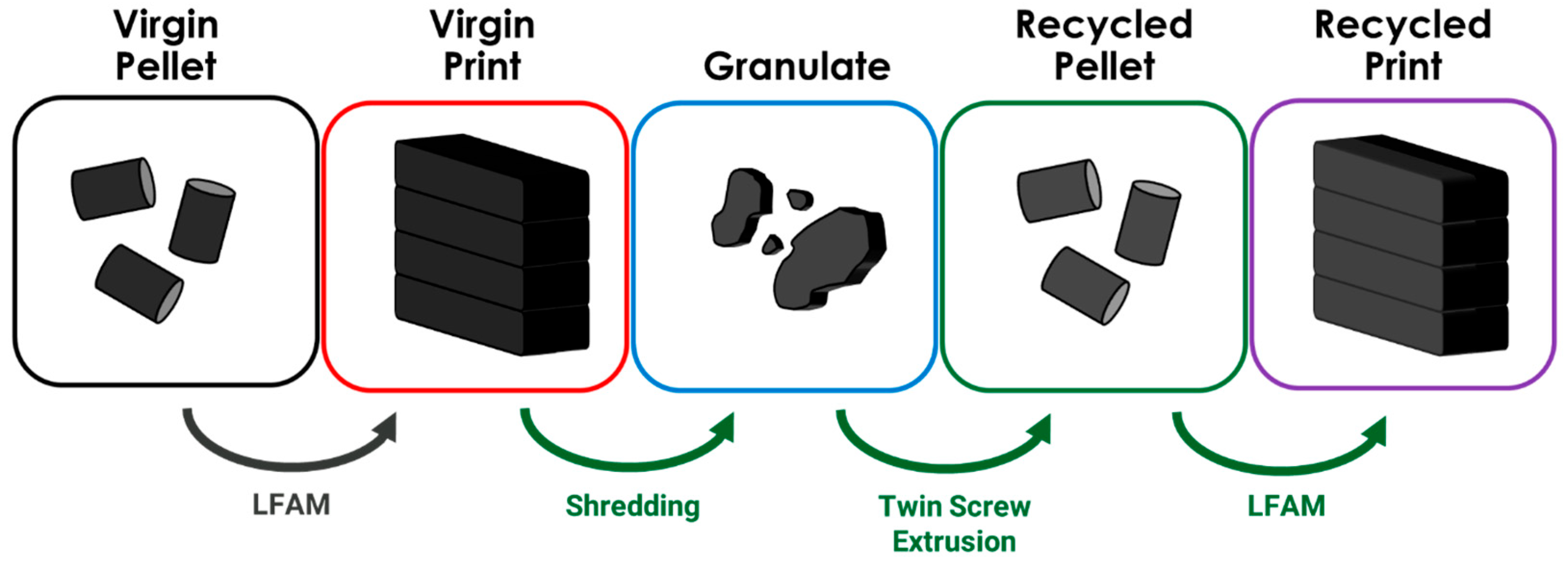
The process flow for this project is summarized in Figure 1. Virgin (0% recycled) CF-PC pellets (black), manufactured by Airtech, were printed into test hexagons for characterization (red). Waste printed materials were shredded/granulated and sieved using a 6 mm mesh. The granulate (blue) was then compounded on a twin screw extruder and cut into pellets (green). These pellets were then re-printed into test samples (purple) in the same way that virgin materials were printed.
Figure 1. Project flow summary that visualizes the material throughout the lifecycle.

2.3. Shredding

Waste CF-PC was shredded using a stacked Cumberland Plastics MR49120 shredder and 56U granulator system (New Berlin, WI, USA) equipped with a 0.6 cm sieve capable of generating granulate at a rate of 2000 kg/h. An industrial blower blew granulate through a cyclonic separator which filtered and captured nanoparticles from the granulate material. A visual of the shredding equipment is shown in Figure S1.

2.4. Twin Screw Extrusion

Compounds for testing were made using Airtech-owned twin screw compounding equipment with screw designs, vents, vacuum, and feed locations for all materials being selected based on best shop practices. All pelletizing and sifting was performed with the applicable equipment to meet an acceptable pellet geometry suitable for LFAM processing. All formulations were continuously monitored, and composition was confirmed with in-process quality validation prior to being sent for additive trials.

2.5. Large-Format Additive Manufacturing (LFAM)

All samples were printed on Airtech-owned in-house LFAM equipment with standard bead geometries. Processing was completed with recommended machine set points and moisture content was checked to be at acceptable levels prior to processing. Test coupons were fabricated for subsequent testing using best shop practices and sized based on the relevant ASTM. A visual of LFAM is shown in Figure S2.

2.6. Fiber Length and Granulate Analysis

Pellets and granulate samples were imaged using an HX-6000 Series Keyence (Itasca, IL, USA) optical microscope. Surface area analysis was performed using Keyence XG VisionEditor software (Version 12). At least 50 samples were measured for each sample type. To prepare the fiber samples for imaging, samples were dissolved in chloroform to yield a 100 mg/mL mixture. The mixture was stirred overnight to dissolve PC and suspend the CF. The fibers were then isolated by vacuum filtration using a Büchner funnel equipped with filter paper. To assure removal of PC from the fibers, the fibers were rinsed further with chloroform. The fibers on filter paper were then dried in a vacuum oven at room temperature overnight and then collected for imaging.

2.7. Mechanical Testing

Mechanical testing samples were machined from test panels printed using LFAM. Dogbone samples were prepared from the center of the printed bead in both the print direction (X) and stacking direction (Z) to measure the samples’ anisotropic tensile strength and modulus. Samples in the Z direction were centered on the panel, whereas samples in the X direction were collected at the center of the bead, cut several inches above the print surface, and machined to ensure interlayer strength did not contribute to changes in observed tensile strength. Z samples were machined at all heights in the sample to ensure variability in thermal history was captured within the sample set. Samples were tested using an MTS servo-hydraulic frame equipped with a 22k lb-f load cell (MTS, Eden Prairie, MN, USA). Samples were equipped with an extensometer and pulled at 1.5 mm/min until fracture. Five samples of each direction and material were tested to ensure statistical significance.

2.8. Thermogravimetric Analysis (TGA)

A TGA Q500 (TA instruments, New Castle, DE, USA) system was used to study the thermal stability of the samples. Samples were heated from room temperature to 80 °C at the heating rate of 10 °C/min and held isothermally for 5 min to remove moisture. Samples were then heated from 80 °C to 700 °C at a rate of 10 °C/min. Experiments were conducted under a nitrogen atmosphere at a sample purge flow rate of 60 mL/min. Each experiment was repeated three times per sample type.

2.9. Dynamic Mechanical Analysis (DMA)

Dynamic mechanical analysis (DMA) was performed on samples that were 60 mm × 10 mm × 3 mm (l × w × h), where all samples were tested in the flexural fixture. First, temperature sweeps were performed to determine the Tg and the storage modulus in the glassy regime; samples were heated from 30 °C to 200 °C at a ramp rate of 3 °C min−1 under an air environment. Fixtures were oscillated at a 0.02% strain and a frequency of 1 Hz, where these parameters were selected from strain and frequency sweeps to ensure all materials remained within the linear viscoelastic regime. Second, heat deflection temperature (HDT) experiments were performed according to a modified form of ASTM D648 under high-stress conditions (1.822 MPa), where samples were heated from 30 °C to 150 °C at a ramp rate of 2 °C min−1 and deflection temperature was recorded at 0.121% strain according to previous work []. A minimum of three samples were tested for each experiment type to ensure statistical significance.

2.10. Coefficient of Thermal Expansion (CTE)

CTE values were measured using a digital image correlation (DIC) oven to characterize thermomechanical performance. The DIC oven is advantageous for LFAM material characterization because this technique better represents thermomechanical response of LFAM parts by accounting for the impact of meso-structural features (multiple layers and beads interacting together) on CTE rather than depending on discrete, localized data points [,,]. Samples were prepared for DIC oven testing by machining a flat, parallel face of interest from each print with final dimensions 50 mm × 50 mm × 3.5 mm. These samples were dried overnight at 120 °C and allowed to cool to room temperature in a desiccator until testing began. Samples were painted white using a matte high-temperature spray paint and speckled using black ink to create a unique contrast for accurate DIC testing. The sample was positioned and imaged at room temperature. The furnace was then heated to 115 °C and the sample was allowed to reach thermal equilibrium before taking a set of images to represent a steady-state response. The set of room temperature and steady state images were uploaded to Correlated Solutions Vic-2D software (Version 7) to calculate thermal-induced strain experienced by the sample. Directional CTE values for each sample tested in the DIC oven were calculated by dividing the difference in strain measurements by the difference in temperature. To best represent the average response of the part, this process was repeated for samples from two unique locations of the part. Each sample was tested twice with corresponding CTE values averaged with a total of four data points to represent each value of each sample tested in the DIC oven.

2.11. Gel Permeation Chromatography (GPC)

Gel permeation chromatography (GPC) was performed to determine the weight average molecular weight (Mw), number average molecular weight (Mn), and polydispersity index (PDI) of PC in the CF-PC composites. Pellets were dissolved in chloroform to yield a 100 mg/mL mixture. The mixtures were vortexed for 10 s and then filtered through a cotton plugged pipette to yield a PC solution with fewer fibers. The solution was then centrifuged at 1000 rpm for 10 min, and the supernatant was collected without disturbing the precipitated carbon fibers. PC was then isolated by removing chloroform in vacuo using a rotary evaporator. The PC was dissolved in HPLC-grade tetrahydrofuran to make a 3 mg/mL solution for GPC analysis. The solutions were syringe-filtered and added to high-performance liquid chromatography (HPLC) vials. GPC was carried out on an Agilent 1260 SEC system with three Phenogel columns (pore sizes of 50, 103, and 106 Å) with a 1 mL/min THF mobile phase at 35 °C and calibration using polystyrene standards. Three samples were run for each sample type.

2.12. Pycnometry

A Micromeritics AccuPyc II 1340 (Norcross, GA, USA) gas pycnometer was used to determine the skeletal density of the PC samples, defined as the ratio of the mass of PC to the sum of the volumes of PC and the closed (or blind) pores within the PC. The sum of these two volumes, sometimes referred to as the skeletal volume, is measured by gas displacement. Samples of 0.3–0.5 g were placed into the 1 cc sample cup of the pycnometer. The cup was purged ten times to ~2 atm with Airgas UHP helium (99.999 purity), and the sample’s skeletal density was determined based on its mass and 5–10 sequential measurements of its skeletal volume. At least 3 samples with 5 replicates each were run for sample type.

2.13. Scanning Electron Microscopy

Fractured tensile bars were sputtered with platinum/palladium and imaged using an EVO MA15 scanning electron microscope (Zeiss Group, Oberkochen, DE, EU) at a scanning voltage of 30 kV in magnifications 100× and 300×.

2.14. Statistical Analysis

Statistical analyses were performed using JMP software (Version 16) (SAS Institute, Cary, NC, USA). Student’s t-test was run to compare samples. A p value less than 0.05 was used to identify statistically significant differences between samples.

3. Results and Discussion

3.1. Mechanical Performance

The functional and mechanical performance in printed parts was measured in both virgin and recycled prints (Figure 2, Table S1). Tensile testing is commonly used in the research literature as a way to measure the mechanical performance of virgin and recycled composites manfuactured using LFAM [,,]. As can be seen, a significant reduction in the average X-direction (direction of the print) tensile strength (21%) in recycled samples was observed. However, no significant difference was calculated in the average Z-direction tensile strength. A significant reduction in the average tensile modulus in the X-direction (39%) was also observed. However, a significant increase in the modulus in the Z-direction was observed (4%). No significant change in the strain at the break in the X- or Z-directions was observed. The reduction in mechanical properties with recycling, as evidenced by the X-direction samples in Figure 2A, is not surprising based on the previous literature, which indicates a propensity for fiber breakage during mechanical recycling []; however, the minor yet significant increase in Z-direction modulus with recycling seen in Figure 2B is surprising. The previous literature has shown that while the load-bearing fiber breakage can reduce mechanical performance, it is also likely to produce print beads with lower surface roughness, potentially allowing for minimized interstitial porosity between the print beads and some mechanical property retention []. Previous research has shown that functional performance in the X-direction in LFAM parts is due to an increased propensity for fiber alignment in the printing direction due to shear forces within the nozzle []. This dataset supports this claim as when visualizing the surface of fractured samples using SEM (Figure S3), it was clear to see evidence of fiber pull-out in the X-direction samples. In the Z-direction, there appears to be less evidence of fiber pull-out and instead fibers appear to have an increased propensity for alignment in the direction transverse to the image plane. No other clear differences are observed between virgin and recycled samples. However, in addition to causing fiber attrition, mechanical recycling can cause reduction in both density (increased porosity) and resin molecular weight (chain scission) [].
Figure 2. Results from mechanical testing of both virgin and recycled CF-PC samples including (A) tensile strength, (B) modulus, and (C) strain at break.

3.2. Particle Size Analysis and Density

It is understood that changes in input particle size in 3D printing can contribute to changes in resulting print density and, thus, mechanical properties []. To understand whether input particle size/shape had any impacts on printed material density, particle size analysis was performed on virgin pellets, recycled granulate, and recycled pellet samples, and pycnometry was run on printed samples using both virgin pellets and recycled pellets (Figure 3). Images of the samples can be visualized in Figure S4. The resulting granulate samples present a significant particle size variation, with an increased propensity for smaller particles on average as compared to pellet samples. The distribution of the granulate sample is consistent with the previous literature, where a screen-based shredding system results in particles whose maximum particle size can be controlled by the screen/sieve used, but this process results in significant dust (or small-size particles) generation []. From this, a broad particle size is expected. However, no significant difference was calculated between the virgin and recycled pellet samples. This result is unsurprising but does confirm that both the virgin and recycled pellets have a similar shape (length and thickness) when processed under the same conditions. However, when these pellets were printed into parts and then analyzed by pycnometry, recycled print samples had a surprising significant increase in average apparent density as compared to virgin print samples (Figure 3B).
Figure 3. (A) Results from quantitative particle size analysis and (B) density as measured by pycnometry.

3.3. Molecular Weight Analysis

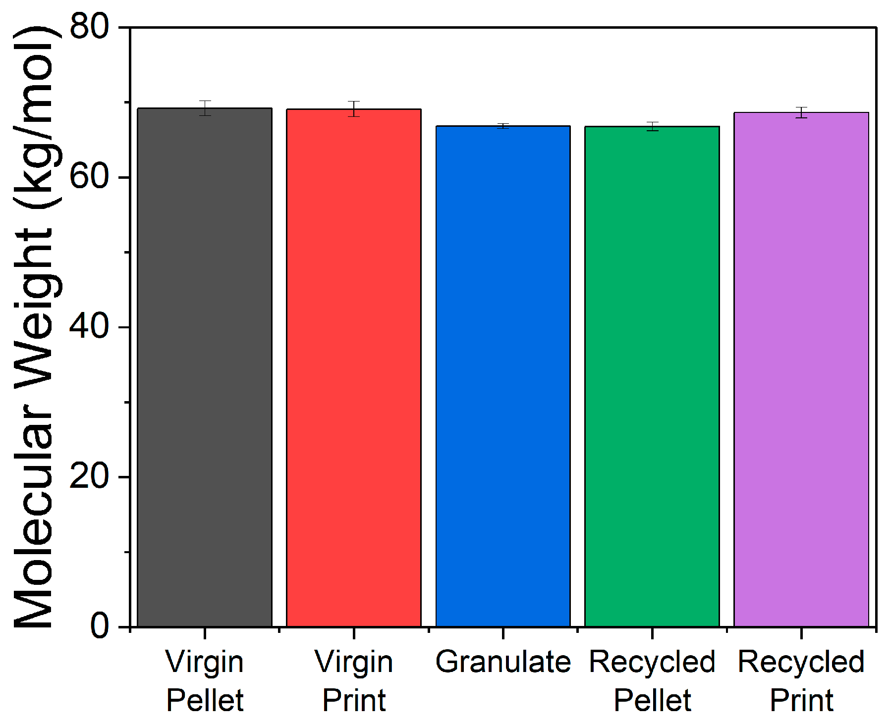
Mechanical recycling can additionally cause chain scission in both the twin screw extrusion and re-manufacturing steps from thermomechanical shear in the screw/nozzle []. GPC was run to quantify the molecular weight at each step of the recycling process (Figure 4). As can be seen, although a reduction in the molecular weight of granulate and recycled pellets (p < 0.05) is observed, no significant difference in molecular weight between printed samples is observed. Thus, it is unlikely that changes in molecular weight contributed to the changes in the functional performance in the printed parts. This result is consistent with the previous literature [,].
Figure 4. Molecular weight of samples at each step in the recycling process.

3.4. Fiber Length Analysis and Fiber Content

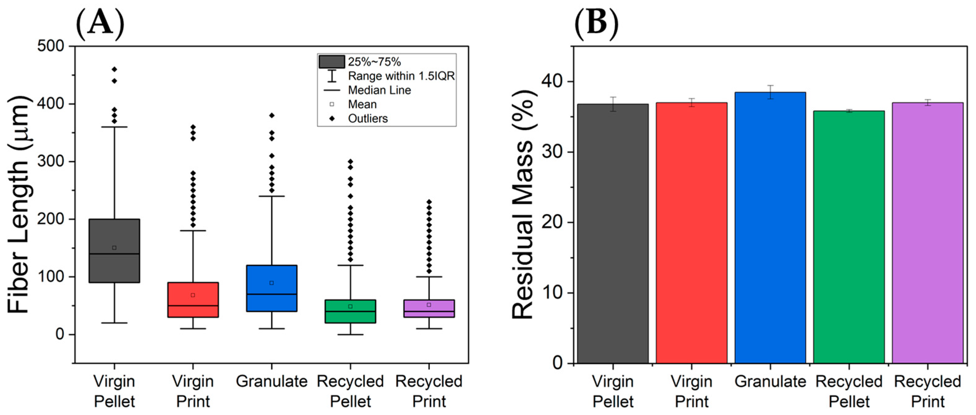
Given the minimal changes in the polymer matrix material as measured via GPC, the reductions in mechanical performance and increased sample density with mechanical recycling are likely to be occurring due to variations in the fiber. As such, fiber length and residual fiber content were measured in samples at each step in the recycling process (Figure 5, Table S2). As can be seen, a significant reduction in fiber length is observed in virgin print samples as compared to virgin pellets (55.0%). This is anticipated and consistent with the previous literature, which has shown that the printing process causes fiber length attrition due to thermomechanical shear in the nozzle [,]. After the composites are granulated, an associated increase in the average fiber length is observed. This is consistent with previous work from this group, which indicated that the cyclonic separator may play a key role in filtering off fine fibers during the shredding/granulating processes, resulting in an overall higher fraction of longer fibers []. Unsurprisingly, the compounding step and printing steps again reduce the fiber lengths, likely due to thermomechanical shear in the screw and nozzle, respectively []. There is also a reduction in the concentration of longer fibers in the recycled print samples as compared to the recycled pellet samples. It is likely that longer fibers have an increased propensity for breaking during the extrusion processes. The average fiber length is significantly reduced (24.6%) in recycled print samples as compared to virgin print samples, indicating that the fiber length is a likely contributor to the reductions in mechanical performance (Figure 2). No significant difference in the residual mass at 600 °C was calculated between the virgin and recycled prints (Figure 5B). Thus, it is unlikely that changes in the CF content contributed to changes observed in the functional performance of the recycled prints as compared to the virgin prints.
Figure 5. (A) Quantitative fiber length analysis results for samples at all stages of the mechanical recycling process and (B) residual mass as measured on TGA at each step in the recycling process.
These results in parallel indicate that fiber length attrition is the most likely contributing factor impacting the mechanical performance in the X-direction of prints. Reduction in fiber length is directly correlated with a resulting reduction in viscosity in the screw (melt compounding) and nozzle (LFAM), as found in previous work from this team []. Because fiber length in recycled printed samples is significantly smaller than in virgin printed samples, it is postulated that this could result in a lower viscosity at the processing temperature and reduce inter-bead porosity, which would explain the higher density of recycled samples []. Previous work has suggested that the mechanism for this is a reduction in alignment of fiber in the direction of the print caused by the reduction in viscosity and thus the shear in the nozzle [,]. This reduction in fiber alignment could be contributing to the reduction in the mechanical performance in the direction of the print and the increase in performance in the transverse direction. It is important to note that previous work has shown that recycling of CF polymers can result in a loss of adhesion at the CF–polymer interface, which can be overcome through the incorporation of nanomaterials, such as carbon nanotubes [,,,]. However, in this work, SEM analysis suggested that there was no visible difference in the quality of the fibers, fiber surface, or the fiber–polymer interface on the fracture surfaces in the samples in this work (Figure S5). Nevertheless, these results indicate that changes in the resin phase of the material may not significantly contribute to changes observed in the density and mechanical properties.

3.5. Thermomechanical Performance

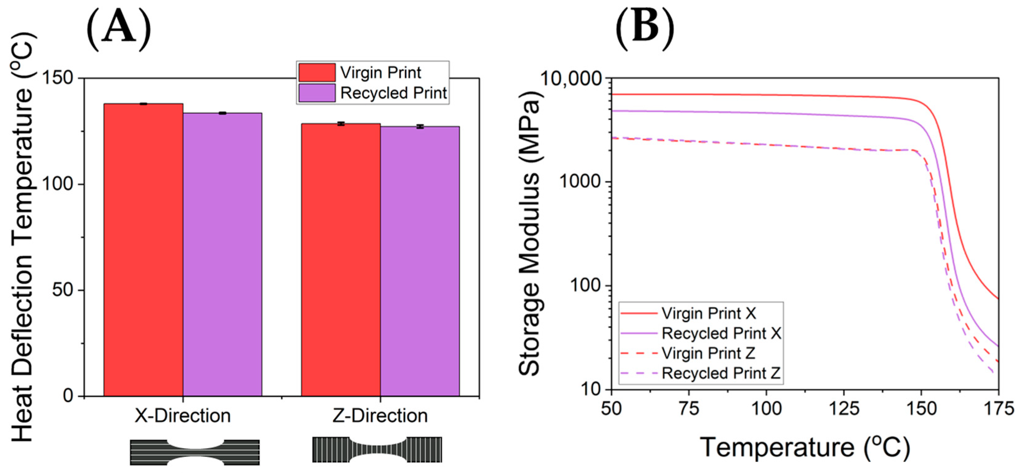
To further quantify the impacts on the material properties relevant to CF-PC in LFAM, the high-stress HDT (1.82 MPa) was measured using DMA. HDT is a critical factor for materials used in tooling at elevated temperatures as any distortion can result in undesired warpage of the final part []. Changes to HDT can significantly reduce the applicability of the material []. A slight (3%) reduction in the HDT in recycled prints was observed as compared to the virgin print (p < 0.05) in the X-direction (Figure 6A). No significant change in the average HDT was observed in the Z-direction samples. These results indicate that the vast majority of the HDT performance was retained, even with a significant reduction in average fiber length in samples. Thus, the resulting reduction in fiber length observed in these samples likely does contribute to the changes in HDT observed, but perhaps not to the same extent as the mechanical performance alone. It is worth noting that the HDT values are measured under a flexural load, rather than tensile load; the alignment of the fiber is less significant when measured under flexural load but is more indicative of the stresses experienced by molds during their application use life. The high HDT retention with mechanical recycling is a strong indicator for the use of these recovered materials in mold and tooling for multiple lifetimes where the use temperatures remain below the Tg of CF-PC.
Figure 6. (A) HDTs (high stress: 1.82 MPa) for virgin print and recycled print samples in the X- and Z-directions and (B) raw DMA thermograms of these samples.
Thermomechanical performance of recycled samples showed a significant reduction in the storage modulus in recycled print samples as compared to virgin prints in the X-direction (Figure 6B). This is expected based on the mechanical data previously observed with these samples and indicates that the fiber length plays a key role in the thermomechanical performance of the parts overall. In addition, a slight (but not statistically significant) reduction in the Tg is observed in recycled print samples (158.5 ± 1.1 °C) in the X-direction as compared to virgin prints (161.4 ± 3.3 °C) in the X-direction. This is expected as the molecular weight did not change between these samples []. In the Z-direction, no significant differences were observed in the storage modulus or Tg. This result suggests that the change in fiber length during recycling likely had more significant impacts on the storage modulus of the material than it did the glass transition temperature. This result suggests the fibers themselves play a key role in resisting the flexural deformation in the sample as loaded in the DMA. However, as the material passes through its Tg, the resistance to flexural deformation is primarily dominated by the resin phase of the material, which results so far have indicated is largely unchanged throughout the recycling process.

3.6. Coefficient of Thermal Expansion

To better understand these phenomena and probe the local microstructural performance, DIC was used to measure local thermal performance (Figure 7A). As can be observed, a significant increase in the X-direction CTE is seen in the recycled print samples as compared to the virgin print samples. In addition, a significant reduction in the average Z-direction strain is observed in recycled prints as compared to the virgin print samples. In addition, the bulk CTE data indicated a significant increase in X-direction CTE and a significant reduction in the Z-direction CTE (Figure 7B). These results in tandem indicate that recycled molds are less capable of resisting thermal deformation in the direction of the print but more likely to resist the deformation in the transverse direction.
Figure 7. (A) Localized thermal strain as measured using DIC analysis in both virgin and recycled samples in the X- and Z-directions and (B) bulk average CTE as measured by DMA in both virgin and recycled samples in X- and Z-directions.
The localized strain and bulk CTE data suggest that as fibers are broken during the recycling process, this likely results in a reduction in fiber alignment in the direction of the bead itself. This conclusion is also supported by the increase in tensile modulus observed in the Z-direction, and the reduction in tensile strength/modulus in the X-direction. Essentially, fibers are less likely to be aligned in the direction of the print in recycled prints as compared to virgin prints. Because of shear stresses in the nozzle of a printer, CF has a propensity for aligning in the direction of the print. The region of highest shear stress in the nozzle has been previously found to be at the edges of the nozzle, which correlates to the edges of the bead in the resulting printed part []. For this reason, LFAM parts tend to have a region of higher alignment at the edges of the bead, with more randomly oriented fiber in the middle of the bead [,]. The strain results in Figure 7A for virgin prints in the Z-direction show distinct bands of high and medium strain values at layer interfaces that seem to diminish as the part was recycled due to less severe impact from fiber alignment []. These results suggest that longer fibers, which have a longer lever arm for the stress/force to act across, are more likely to be driven to alignment by the apparent torque applied by the shear stresses at the edges of the bead in the direction of the bead. Shorter fibers experience less force over their lever arm and therefore less torque. Thus, they are less likely to align in the direction of the print itself. When these parts are then recycled, and the resulting fiber length is significantly reduced in the compounding and re-printing step, these fibers cannot align as effectively along the edges of the bead as they did in their first lifetime. As such, they are more randomly oriented in the printed part. This phenomenon could explain the local strain plot which (in recycled samples in the Z-direction) shows less distinct bands of strain due to less fiber alignment in recycled parts. This is also likely supported by the photos of the surface of the failed samples (Figure S6), where there are visible layers at a consistent height to the layer height on the X-direction samples (~0.5 cm) that do not appear visibly in the Z-direction samples. The bulk CTE results are also consistent with this phenomenon as more randomly oriented, shorter fibers will result in reduced ability to resist thermal expansion in the X-direction (and an associated increase in CTE), as well as an increase in the ability to resist thermal expansion in the Z-direction.

4. Conclusions

This study demonstrates the promising potential of mechanically recycling CF-PC for industrial applications in LFAM while identifying and addressing critical challenges inherent to the recycling process. Quantitative analysis revealed that
  • Mechanical recycling significantly reduced fiber length, with a 55.0% decrease observed during the transition from virgin pellets to virgin prints due to thermomechanical shear in the nozzle.
  • Recycled prints exhibited a further 24.6% reduction in average fiber length compared to virgin prints, while fiber lengths remained largely unaffected during shredding.
  • This reduction in fiber length correlated with a 21% drop in X-direction tensile strength, a 39% reduction in tensile modulus, and a 6.8% increase in X-direction CTE.
  • Conversely, Z-direction modulus improved by 4%, Z-direction strength remained unchanged, and sample density increased, indicating reduced bead porosity.
These shifts likely result from the diminished ability of shorter fibers to align under shear forces during printing in the recycled samples, which could alter the material’s flow properties during manufacturing and resulting interlayer bonding/surface dynamics. While the resin phase remained largely stable, with molecular weight remaining constant across recycling steps, these mechanical and thermomechanical changes suggest the need for targeted innovation to enable circularity in LFAM. Now that fiber length attrition during extrusion and printing is quantified and understood, it must be addressed and subsequently overcome to maintain alignment and performance to enable the production of recycled composites that meet specifications. Interestingly, these results are consistent with previous studies on the recycling of LFAM composites made using ABS and PLA [,,]. This suggests the degradation pathway in PC composites is likely to be consistent with most if not all thermoplastic resin systems when printed at large scale. Future work will require the development of methodologies to increase average fiber length in recycled samples or minimize fiber length degradation in the manufacturing process itself. Additionally, there is a need to understand the long-term impacts, such as aging and cyclic loading in the printed parts, which can be useful for tools/molds made for LFAM that can see cyclic use. Finally, work is needed to quantify the performance of this material over multiple use/recycling cycles. These findings emphasize the importance of developing strategies to mitigate fiber breakage or otherwise compensate for these changes/reductions in viscosity, advancing the circularity and sustainability of LFAM materials.

Supplementary Materials

The following supporting information can be downloaded at https://www.mdpi.com/article/10.3390/polym17222981/s1, Figure S1: A visual of the mechanical recycling equipment used in this work. Herein, a stacked shredder/granulator system equipped with a 5 cm sieve on the shredder and a 1 cm sieve on the granulator is shown; Figure S2: In this work, large-format additive manufacturing (LFAM) is purging carbon fiber-filled composite material into a metal baking pan. A photo of an LFAM system is attached purely to aid the reader in visualization of the manufacturing technology and its scale; Figure S3: Scanning electron microscopy (SEM) of fracture surfaces. Top row shows virgin prints in the (A) X-direction and (B) Z-direction. Bottom row shows recycled prints in the (C) X-direction and (D) Z-direction. Evidence of fiber pull-out can be seen in X-direction prints. Fibers tend to be aligned perpendicular to the fracture surface in Z-direction samples; Figure S4: Visuals for the particles generated by mechanical recycling as compared to virgin pellets. (A) Virgin pellets, (B) granulate, (C) 100% recycled CF-PC samples prior to manufacturing. As can be seen, recycled and virgin pellet samples appear visibly similar. However, granulate samples appear to have a more distributed particle size with increased presence of smaller particles; Figure S5: Zoomed images of the fracture surfaces in virgin and recycled print samples. No visible differences in the quality of the fibers or the quality of the fiber–resin interface can be observed; Figure S6: Images of fracture surfaces of samples. X-direction (direction of the print) samples show visible printed layers on the fracture surface. Z-direction samples do not show such a layered structure. Arrows in the images point to some of the layers to aid the eye. This is to be expected as fibers are expected to be aligned in the X-direction; Table S1: Compiled thermal, mechanical, and density data for the printed samples in this work; Table S2: Compiled fiber length and particle size analysis for samples measured in this work.

Author Contributions

Conceptualization, M.K.; data curation, M.K.; formal analysis, M.K., A.M.H., K.C., T.C. and W.M.G.; investigation, M.K., G.H., R.B. and Z.S.; methodology, M.K., A.M.H., R.B., Z.S., N.M., A.L.S.A., K.S., K.C., T.C. and D.X.B.; project administration, G.H.; resources, G.H. and Z.S.; supervision, W.M.G., C.D. and S.O.; validation, M.K. and R.B.; visualization, M.K.; writing—original draft, M.K.; writing—review and editing, A.M.H., R.B., K.C., T.C. and W.M.G. All authors have read and agreed to the published version of the manuscript.

Funding

The work was funded by Oak Ridge National Laboratory operated by UT-Battelle, LLC. under Contract No. DE-AC05-00OR22725 with the U.S. Department of Energy.

Data Availability Statement

The datasets presented in this article are not readily available because the dataset is protected as part of the ongoing research program. Requests to access the datasets should be directed to the corresponding author: koreym@ornl.gov.

Acknowledgments

The authors want to thank Adwoa Owusu for performing the SEM on samples in the Supplemental Information of this publication.

Conflicts of Interest

The authors G.H., R.B., and Z.S. are employed by the company Airtech International Inc. The remaining authors declare that the research was conducted in the absence of any commercial or financial relationships that could be construed as potential conflicts of interest.

References

  1. Hsissou, R.; Seghiri, R.; Benzekri, Z.; Hilali, M.; Rafik, M.; Elharfi, A. Polymer composite materials: A comprehensive review. Compos. Struct. 2021, 262, 113640. [Google Scholar] [CrossRef]
  2. Egbo, M.K. A fundamental review on composite materials and some of their applications in biomedical engineering. J. King Saud Univ.-Eng. Sci. 2021, 33, 557–568. [Google Scholar] [CrossRef]
  3. Schweizer, K.; Bhandari, S.; Lopez-Anido, R.A.; Korey, M.; Tekinalp, H. Recycling Large-Format 3D Printed Polymer Composite Formworks Used for Casting Precast Concrete–Technical Feasibility and Challenges. J. Compos. Constr. 2024, 28, 1–16. [Google Scholar] [CrossRef]
  4. Sproul, E.; Williams, M.; Rencheck, M.L.; Korey, M.; Ennis, B. Life Cycle Assessment of Wind Turbine Blade Recycling Approaches in the United States. In Proceedings of the 43rd Risø International Symposium on Materials Science: Composite for Wind Energy: Manufacturing, Operation and End-of-Life, Roskilde, Denmark, 4–7 September 2023. [Google Scholar]
  5. Zhang, J.; Lin, G.; Vaidya, U.; Wang, H. Past, present and future prospective of global carbon fibre composite developments and applications. Compos. Part B Eng. 2023, 250, 110463. [Google Scholar] [CrossRef]
  6. Air, A.; Shamsuddoha, M.; Gangadhara Prusty, B. A review of Type V composite pressure vessels and automated fibre placement based manufacturing. Compos. Part B Eng. 2023, 253, 110573. [Google Scholar] [CrossRef]
  7. Thermoplastic Composites Market Size, Share & Industry Analysis, By Fiber Type (Glass Fiber-reinforced Polymer, Carbon Fiber-reinforced Polymer, and Others), By Resin Type (Polypropylene (PP), Polyamide (PA), Polyetheretherketone (PEEK), and Others), By Application (Transportation, Construction, Electrical & Electronics, Sports & Leisure, and Others), and Regional Forecast, 2024–2032. 2025, Fortune Business Insights. Available online: https://www.fortunebusinessinsights.com/thermoplastic-composites-market-110534 (accessed on 5 June 2025).
  8. Global Thermoset Composites Market Size By Fiber Type, By Resin Type, By Geographic Scope And Forecast. 2025, Verified Market Research. Available online: https://www.verifiedmarketresearch.com/product/thermoset-composites-market/ (accessed on 5 June 2025).
  9. Liu, X.Q.; Huang, W.; Jiang, Y.H.; Zhu, J.; Zhang, C.Z. Preparation of a bio-based epoxy with comparable properties to those of petroleum-based counterparts. Express Polym. Lett. 2012, 6, 293–298. [Google Scholar] [CrossRef]
  10. Oliveux, G.; Dandy, L.O.; Leeke, G.A. Current status of recycling of fibre reinforced polymers: Review of technologies, reuse and resulting properties. Prog. Mater. Sci. 2015, 72, 61–99. [Google Scholar] [CrossRef]
  11. Rathore, N.; Panwar, N.L. Environmental impact and waste recycling technologies for modern wind turbines: An overview. Waste Manag. Res. 2023, 41, 744–759. [Google Scholar] [CrossRef]
  12. Henao, Y.; Grubert, E.; Korey, M.; Bank, L.C.; Gentry, R. Life Cycle Assessment and Life Cycle Cost Analysis of Repurposing Decommissioned Wind Turbine Blades as High-Voltage Transmission Poles. J. Constr. Eng. Manag. 2024, 150, 1–15. [Google Scholar] [CrossRef]
  13. Hartwig, G.; Evans, D. Nonmetallic Materials and Composites at Low Temperatures 3, 1st ed.; Plenum Press: New York, NY, USA, 1986. [Google Scholar]
  14. Dahltram C250CF Thermoplastic Pellet Mid Temp 25 kgs. Available online: https://estore.airtechintl.com/print-techr.html (accessed on 5 June 2025).
  15. Verrey, J.; Wakeman, M.D.; Michaud, V.; Månson, J.A.E. Manufacturing cost comparison of thermoplastic and thermoset RTM for an automotive floor pan. Compos. Part A Appl. Sci. Manuf. 2006, 37, 9–22. [Google Scholar] [CrossRef]
  16. Simpson, T. With Additive Manufacturing, No Tooling Is Required, in Compositesworld. 2018. Available online: https://www.additivemanufacturing.media/articles/with-additive-manufacturing-no-tooling-is-required (accessed on 5 June 2025).
  17. Xu, W.; Jambhulkar, S.; Zhu, Y.; Ravichandran, D.; Kakarla, M.; Vernon, B.; Lott, D.G.; Cornella, J.L.; Shefi, O.; Miquelard-Garnier, G.; et al. 3D printing for polymer/particle-based processing: A review. Compos. Part B Eng. 2021, 223, 109102. [Google Scholar] [CrossRef]
  18. Roschli, A.; Post, B.K.; Chesser, P.C.; Sallas, M.; Love, L.J.; Gaul, K.T. Precast concrete molds fabricated with big area additive manufacturing. In Proceedings of the 29th Annual International Solid Freeform Fabrication Symposium, Austin, TX, USA, 13–15 August 2018. [Google Scholar]
  19. Walker, R.; Webb, D.; Bhagia, S.; Black, N.; Collier, A.; Ozcan, S.; Kunc, V.; Duty, C. Enabling Recycling Of Composites: Understanding The Impacts Of Multiple Thermal Processing Cycles. In Proceedings of the SAMPE North America Conference & Exhibition, Seattle, WA, USA, 17–20 April 2023. [Google Scholar]
  20. Love, L.J.; Kunc, V.; Rios, O.; Duty, C.E.; Elliott, A.M.; Post, B.K.; Smith, R.J.; Blue, C.A. The importance of carbon fiber to polymer additive manufacturing. J. Mater. Res. 2014, 29, 1893–1898. [Google Scholar] [CrossRef]
  21. Armstrong, K.O.; Kamath, D.; Zhao, X.; Rencheck, M.L.; Tekinalp, H.; Korey, M.; Hun, D.; Ozcan, S. Life cycle cost, energy, and carbon emissions of molds for precast concrete: Exploring the impacts of material choices and additive manufacturing. Resour. Conserv. Recycl. 2023, 197, 107117. [Google Scholar] [CrossRef]
  22. Korey, M.; Rencheck, M.L.; Tekinalp, H.; Wasti, S.; Wang, P.; Bhagia, S.; Walker, R.; Smith, T.; Zhao, X.; Lamm, M.E.; et al. Recycling polymer composite granulate/regrind using big area additive manufacturing. Compos. Part B Eng. 2023, 256, 110652. [Google Scholar] [CrossRef]
  23. Song, R.; Telenko, C. Material and energy loss due to human and machine error in commercial FDM printers. J. Clean. Prod. 2017, 148, 895–904. [Google Scholar] [CrossRef]
  24. Walker, R.; Korey, M.; Hubbard, A.M.; Clarkson, C.M.; Corum, T.; Smith, T.; Hershey, C.J.; Lindahl, J.; Ozcan, S.; Duty, C. Recycling of CF-ABS machining waste for large format additive manufacturing. Compos. Part B Eng. 2024, 275, 111291. [Google Scholar] [CrossRef]
  25. Skelton, Z.I.; Jackson, A.G.; Lunn, P.A. Long term autoclave cycling of additive manufactured demonstration tool. In Proceedings of the SAMPE, Seattle, WA, USA, 17–20 April 2023. [Google Scholar]
  26. Cruz Sanchez, F.A.; Boudaoud, H.; Camargo, M.; Pearce, J.M. Plastic recycling in additive manufacturing: A systematic literature review and opportunities for the circular economy. J. Clean. Prod. 2020, 264, 121602. [Google Scholar] [CrossRef]
  27. Zhang, Y.; Pontikes, Y.; Lessard, L.; Willem van Vuure, A. Recycling and valorization of glass fibre thermoset composite waste by cold incorporation into a sustainable inorganic polymer matrix. Compos. Part B Eng. 2021, 223, 109120. [Google Scholar] [CrossRef]
  28. Coughlin, D.; Ludwig, C.; Ozcan, S.; Hartman, D.; Ginder, R. Controlled Pyrolysis: A Robust Scalable Composite Recycling Technology; The Institute for Advanced Composites Manufacturing Innovation: U.S. Department of Energy: Knoxville, TN, USA, 2021. [Google Scholar] [CrossRef]
  29. Stelzer, P.S.; Cakmak, U.; Eisner, L.; Doppelbauer, L.K.; Kállai, I.; Schweizer, G.; Prammer, H.K.; Major, Z. Experimental feasibility and environmental impacts of compression molded discontinuous carbon fiber composites with opportunities for circular economy. Compos. Part B Eng. 2022, 234, 109638. [Google Scholar] [CrossRef]
  30. Caltagirone, P.E.; Ginder, R.S.; Ozcan, S.; Li, K.; Gay, A.M.; Stonecash, J.; Steirer, K.X.; Cousins, D.; Kline, S.P.; Maxey, A.T.; et al. Substitution of virgin carbon fiber with low-cost recycled fiber in automotive grade injection molding polyamide 66 for equivalent composite mechanical performance with improved sustainability. Compos. Part B Eng. 2021, 221, 109007. [Google Scholar] [CrossRef]
  31. Zhao, J.; Liu, P.; Yue, J.; Huan, H.; Bi, G.; Zhang, L. Recycling glass fibers from thermoset epoxy composites by in situ oxonium-type polyionic liquid formation and naphthalene-containing superplasticizer synthesis with the degradation solution of the epoxy resin. Compos. Part B Eng. 2023, 254, 110435. [Google Scholar] [CrossRef]
  32. Michener, J.; Saint-Vincent, P.; Cahill, J.; Drufva, E.; Valentino, H.; Kertesz, V.; Parks, J.; Demerdash, O.; Gainaru, C.; Bocharova, V.; et al. Discovery and engineering of nylon hydrolases for PA66 recycling. In Proceedings of the Enzyme Engineering XXVII, Singapore, 1–6 October 2023. [Google Scholar]
  33. Bocharova, V.; Drufva, E.E.; Cahill, J.F.; Popov, I.; Dishner, I.T.; Zhou, M.; Jung, G.S.; Ullman, A.M.; Carper, D.L.; Damron, J.T.; et al. Factors modulating the hydrolysis of Nylon-6,6 by a nylon hydrolase enzyme. Polym. Chem. 2025, 16, 1858–1868. [Google Scholar] [CrossRef]
  34. Ma, D.; Wang, Y.; Sarazen, M.L.; Boyer, C.; Saito, T.; Duan, H.; Huang, W. Catalysis for plastic deconstruction and upcycling. Cell Rep. Phys. Sci. 2024, 5, 102209. [Google Scholar] [CrossRef]
  35. Zhao, X.; Korey, M.; Li, K.; Copenhaver, K.; Tekinalp, H.; Celik, S.; Kalaitzidou, K.; Ruan, R.; Ragauskas, A.J.; Ozcan, S. Plastic waste upcycling toward a circular economy. Chem. Eng. J. 2022, 428, 131928. [Google Scholar] [CrossRef]
  36. Korey, M.; Sproul, E.; Rencheck, M.L.; Ennis, B.L. Development of wind turbine blade recycling baselines in the United States. IOP Conf. Ser. Mater. Sci. Eng. 2023, 1293, 012018. [Google Scholar] [CrossRef]
  37. Romani, A.; Perusin, L.; Ciurnelli, M.; Levi, M. Characterization of PLA feedstock after multiple recycling processes for large-format material extrusion additive manufacturing. Mater. Today Sustain. 2024, 25, 100636. [Google Scholar] [CrossRef]
  38. Copenhaver, K.; Smith, T.; Armstrong, K.; Kamath, D.; Rencheck, M.; Bhagia, S.; Korey, M.; Lamm, M.; Ozcan, S. Recyclability of additively manufactured bio-based composites. Compos. Part B Eng. 2023, 255, 110617. [Google Scholar] [CrossRef]
  39. Wasti, S.; Hubbard, A.M.; Clarkson, C.M.; Johnston, E.; Tekinalp, H.; Ozcan, S.; Vaidya, U. Long coir and glass fiber reinforced polypropylene hybrid composites prepared via wet-laid technique. Compos. Part C Open Access 2024, 14, 100445. [Google Scholar] [CrossRef]
  40. Corum, T.; O’Connell, J.; Brackett, J.; Spender, R.; Hassen, A.; Duty, C. Characterizing the Thermal-Induced Distortion of Large-Scale Polymer Composite Printed Structures. In Proceedings of the the 33rd Annual International Solid Freeform Fabrication Symposium, Austin, TX, USA, 25–27 July 2022. [Google Scholar]
  41. Corum, T.M.; O’Connell, J.C.; Brackett, J.C.; Hassen, A.A.; Duty, C.E. Measuring thermomechanical response of large-format printed polymer composite structures via digital image correlation. Addit. Manuf. 2024, 94, 104479. [Google Scholar] [CrossRef]
  42. Duty, C.; Ajinjeru, C.; Kishore, V.; Compton, B.; Hmeidat, N.; Chen, X.; Liu, P.; Hassen, A.A.; Lindahl, J.; Kunc, V. What makes a material printable? A viscoelastic model for extrusion-based 3D printing of polymers. J. Manuf. Process. 2018, 35, 526–537. [Google Scholar] [CrossRef]
  43. Butenegro, J.A.; Bahrami, M.; Abenojar, J.; Martinez, M.A. Recent Progress in Carbon Fiber Reinforced Polymers Recycling: A Review of Recycling Methods and Reuse of Carbon Fibers. Materials 2021, 14, 6401. [Google Scholar] [CrossRef] [PubMed]
  44. Boroujeni, A.Y.; Tehrani, M.; Nelson, A.J.; Al-Haik, M. Effect of carbon nanotubes growth topology on the mechanical behavior of hybrid carbon nanotube/carbon fiber polymer composites. Polym. Compos. 2016, 37, 2639–2648. [Google Scholar] [CrossRef]
  45. Fazeli, M.; Jayaprakash, S.; Baniasadi, H.; Abidnejad, R.; Lipponen, J. Recycled carbon fiber reinforced composites: Enhancing mechanical properties through co-functionalization of carbon nanotube-bonded microfibrillated cellulose. Compos. Part A Appl. Sci. Manuf. 2024, 180, 108097. [Google Scholar] [CrossRef]
  46. Aldosari, S.M.; AlOtaibi, B.M.; Alblalaihid, K.S.; Aldoihi, S.A.; AlOgab, K.A.; Alsaleh, S.S.; Alshamary, D.O.; Alanazi, T.H.; Aldrees, S.D.; Alshammari, B.A. Mechanical Recycling of Carbon Fiber-Reinforced Polymer in a Circular Economy. Polymers 2024, 16, 1363. [Google Scholar] [CrossRef] [PubMed]
Disclaimer/Publisher’s Note: The statements, opinions and data contained in all publications are solely those of the individual author(s) and contributor(s) and not of MDPI and/or the editor(s). MDPI and/or the editor(s) disclaim responsibility for any injury to people or property resulting from any ideas, methods, instructions or products referred to in the content.

Article Metrics

Citations

Article Access Statistics

Article metric data becomes available approximately 24 hours after publication online.