
Surface Ion-Imprinted Polypropylene Fibers for Selective and Rapid Adsorption of Borate Ions: Preparation, Characterization, and Performance Study

Abstract
1. Introduction
2. Experimental
2.1. Experimental Materials
2.2. Experimental Instruments
2.3. Experimental Methods
2.3.1. Material Pretreatment
2.3.2. Plasma Modification
2.3.3. Liquid-Phase Grafting Treatment
2.3.4. The Ring-Opening Amination Reaction
2.3.5. Preparation of the Borate-Imprinted Fiber I-(PP-g-GMA-NMDG)
2.3.6. Adsorption Experiment
2.3.7. Calculation of the Grafting Rate and Adsorption Amount
3. Results and Discussion
3.1. Optimization of the Low-Temperature Plasma Modification Conditions
3.1.1. The Influence of Different Discharge Powers on GMA Grafting
3.1.2. The Influence of Different Atmospheres on GMA Grafting
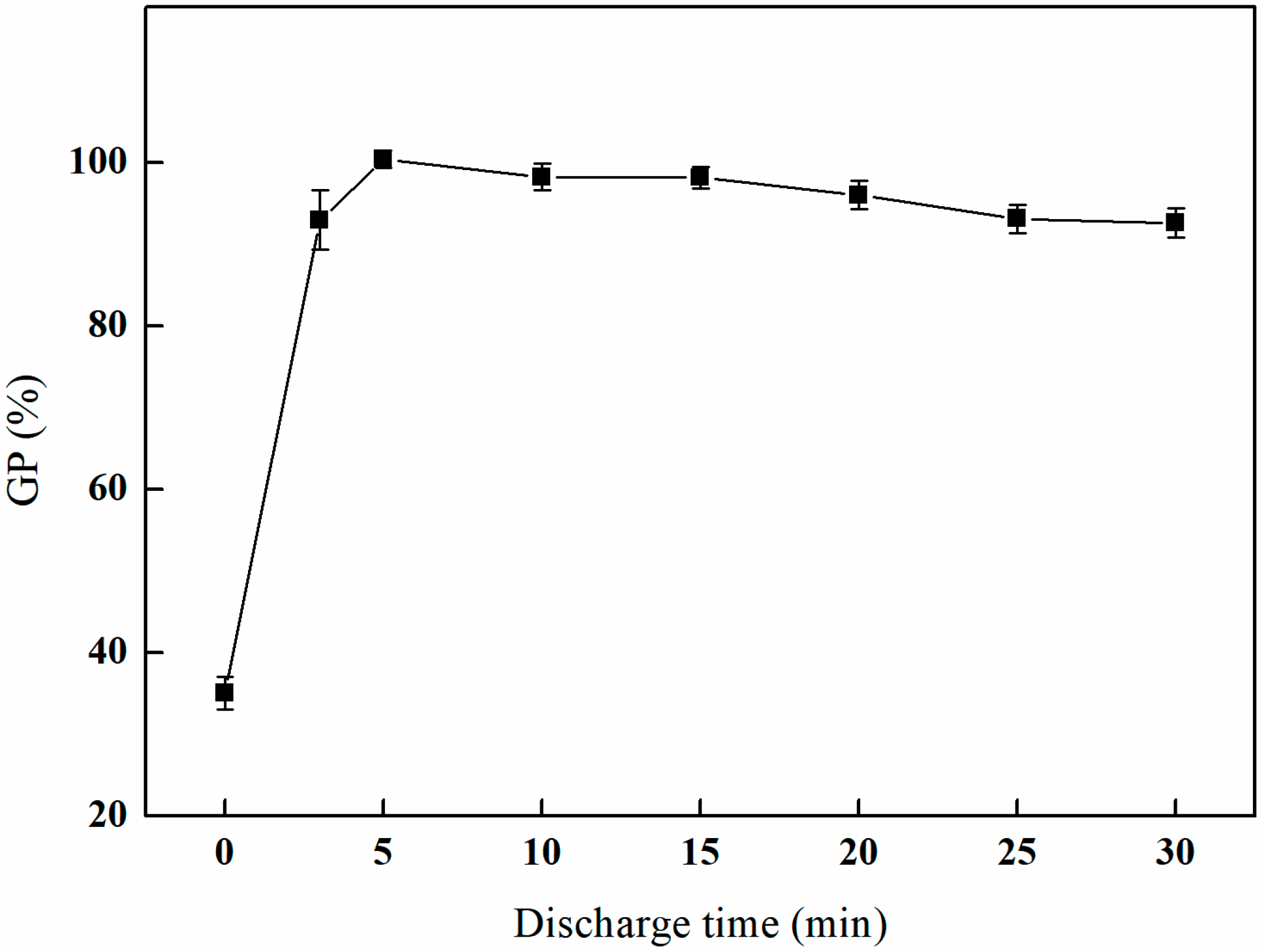
3.1.3. The Effect of Different Discharge Times on GMA Grafting
3.2. Optimization of the Liquid-Phase Grafting Conditions
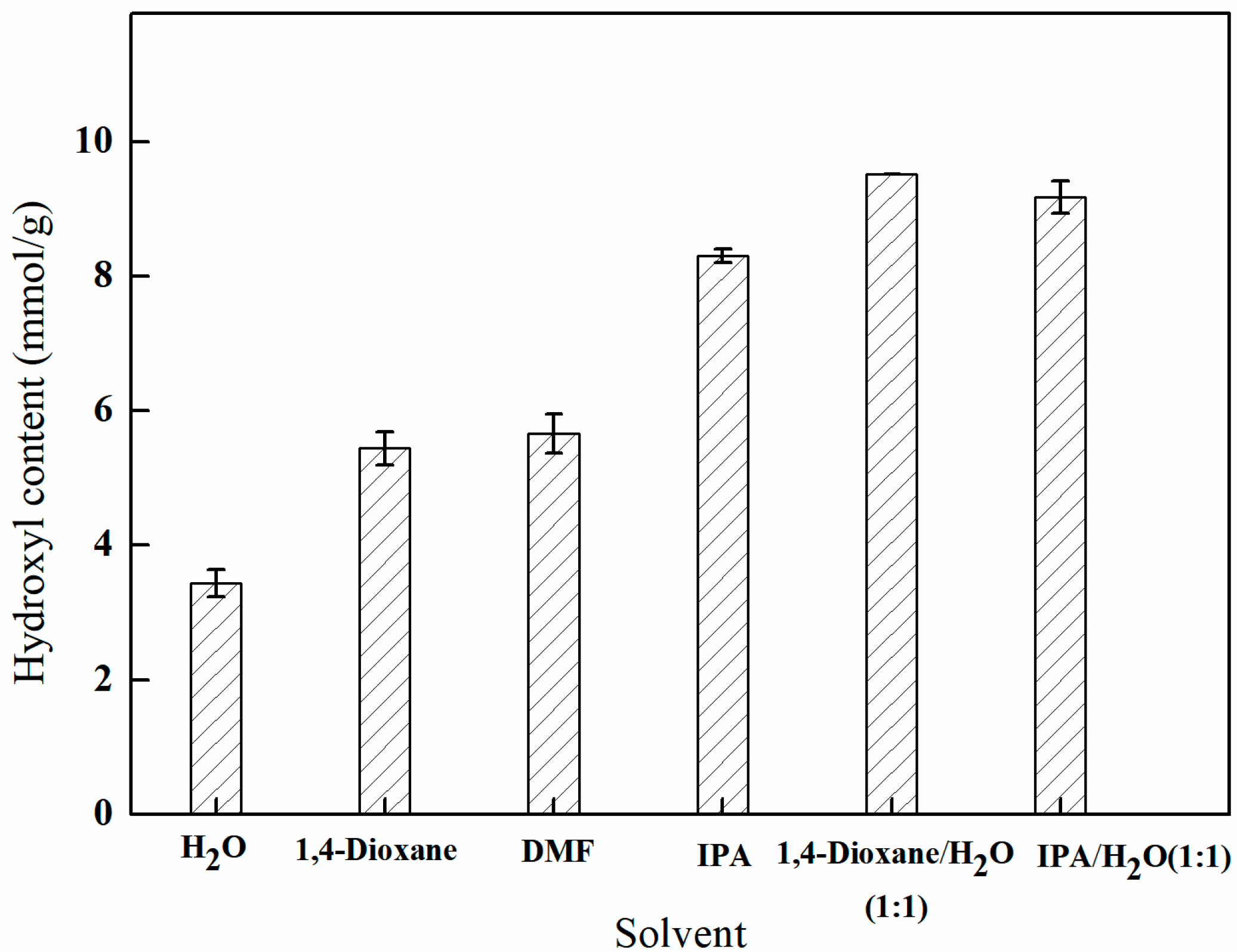
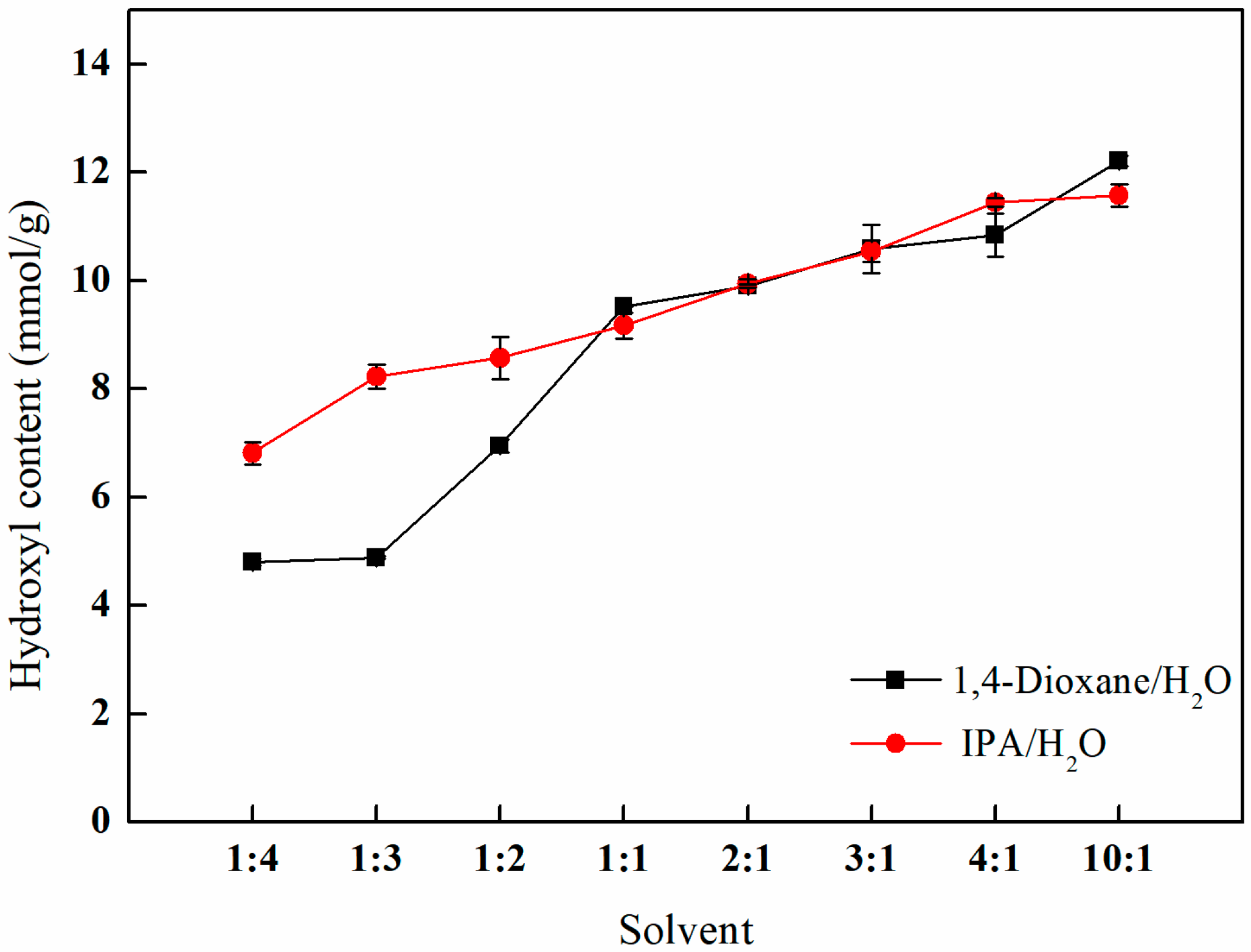
3.2.1. The Influence of Different Solvent Environments on GMA Grafting
3.2.2. The Effect of Different GMA Concentrations on GMA Grafting
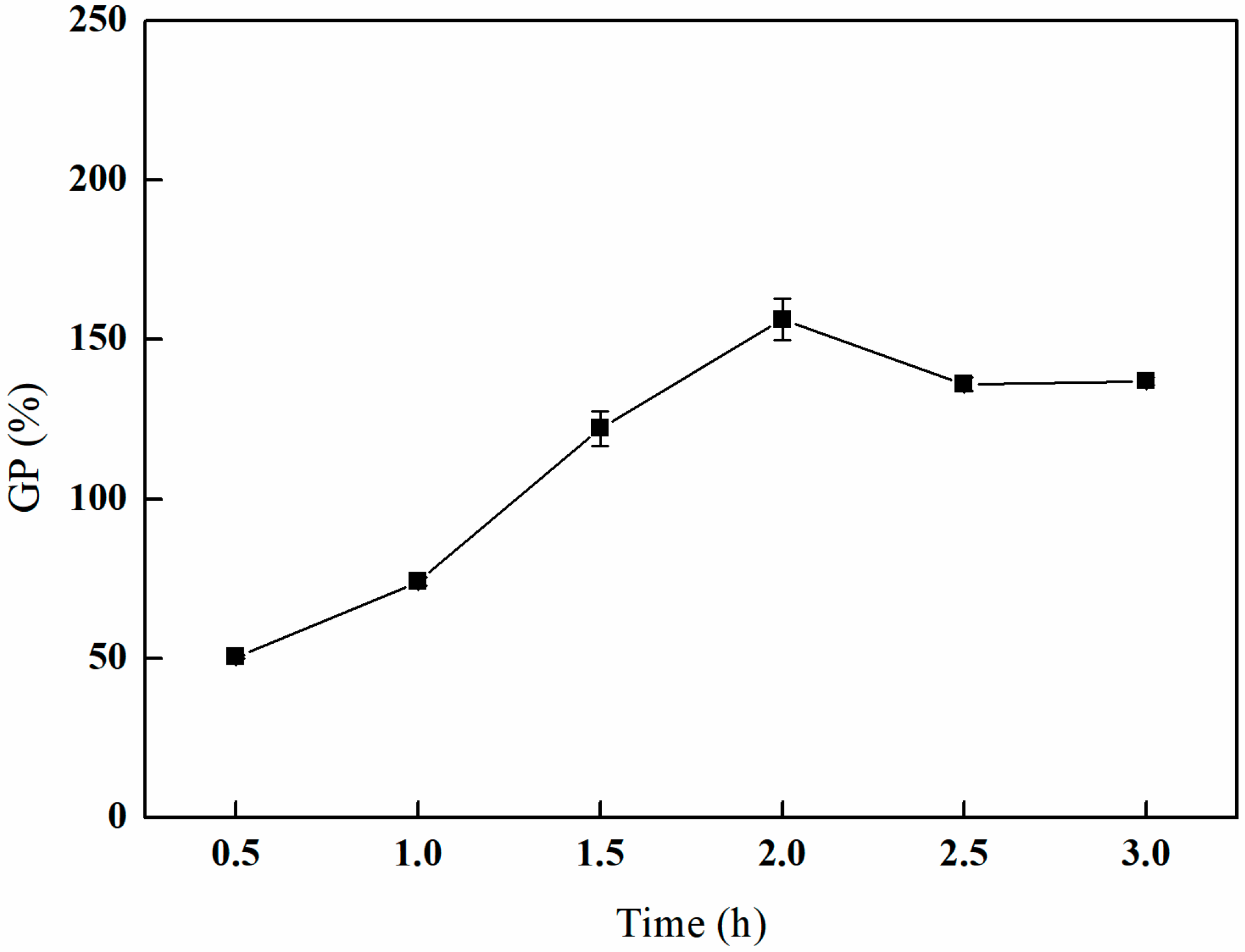
3.2.3. The Effect of Different Grafting Times on GMA Grafting
3.3. Response Surface Optimization Experiment
0.10608 Y2 + 22.102 Z2
3.4. Optimization of Open-Loop Amination Conditions
3.4.1. The Influence of Different Solvent Environments on Amination Efficiency
3.4.2. The Effect of Different Open-Loop Times on Amination Efficiency
3.4.3. The Effect of Different Open-Loop Temperatures on Amination Efficiency
3.4.4. The Influence of Different NMDG Amounts on the Amination Effect
3.5. Optimization of the Preparation Conditions for Imprinted Fibers
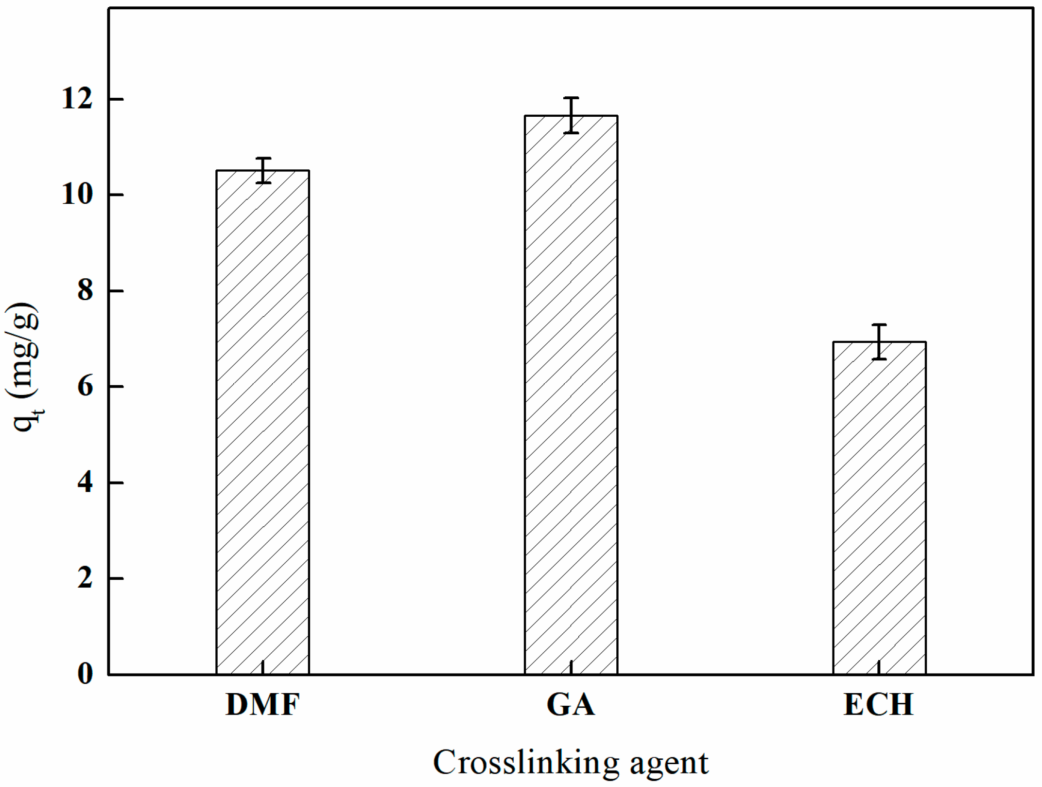
3.5.1. The Influence of Different Crosslinking Agents on Adsorption Efficiency
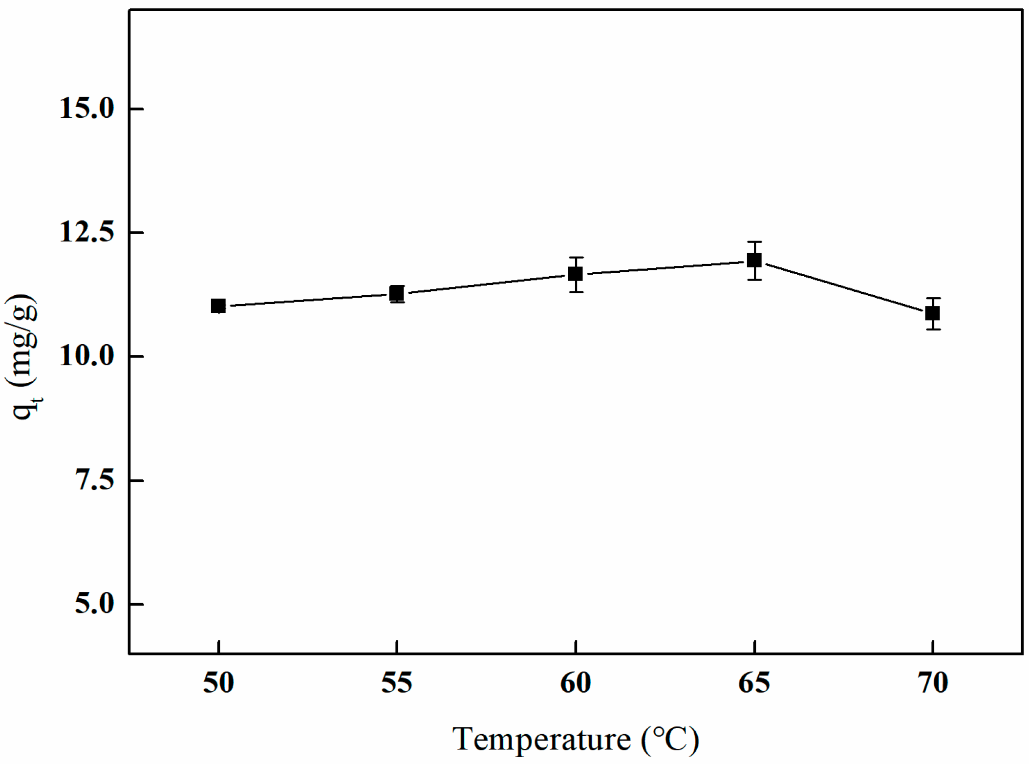
3.5.2. The Influence of Different Crosslinking Temperatures on Adsorption Efficiency
3.5.3. The Effect of Different Crosslinking Doses on Adsorption Efficiency
3.5.4. The Influence of Different Crosslinking Times on Adsorption Efficiency
3.6. Characterization
3.6.1. FT-IR
3.6.2. XRD
3.6.3. TGA
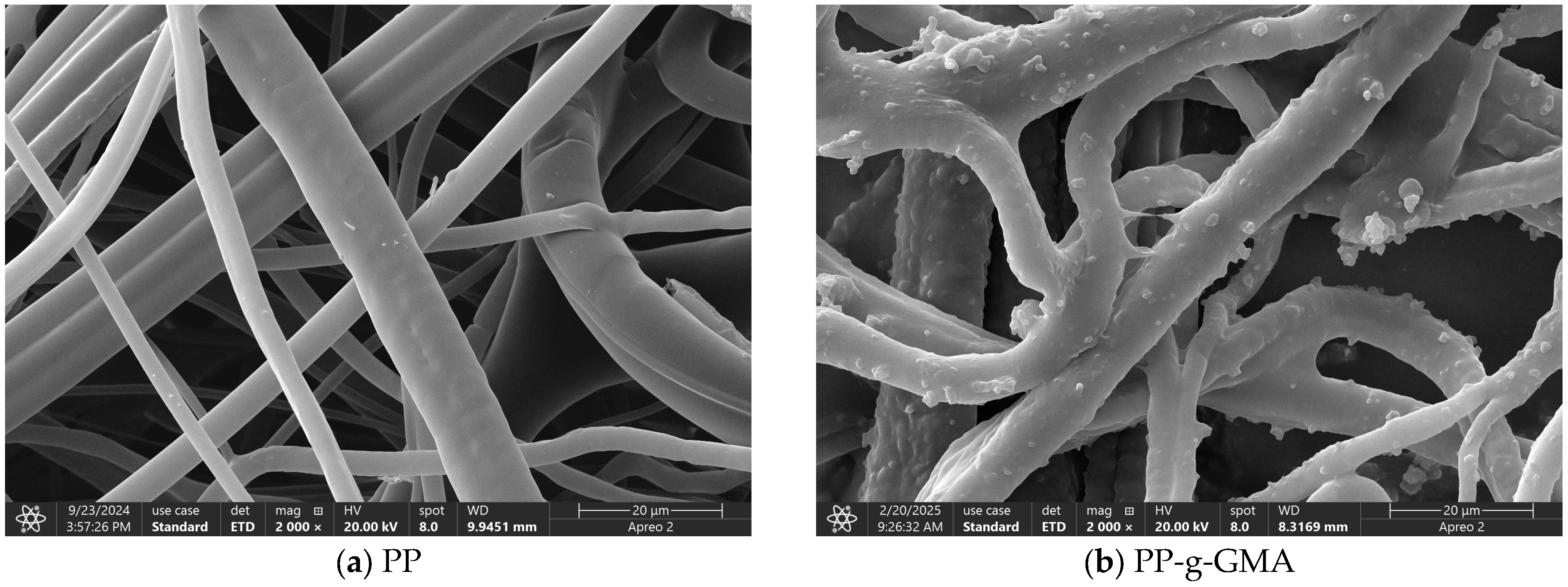
3.6.4. SEM
3.6.5. EDS
3.6.6. WCA
3.7. Exploration of Adsorption Performance
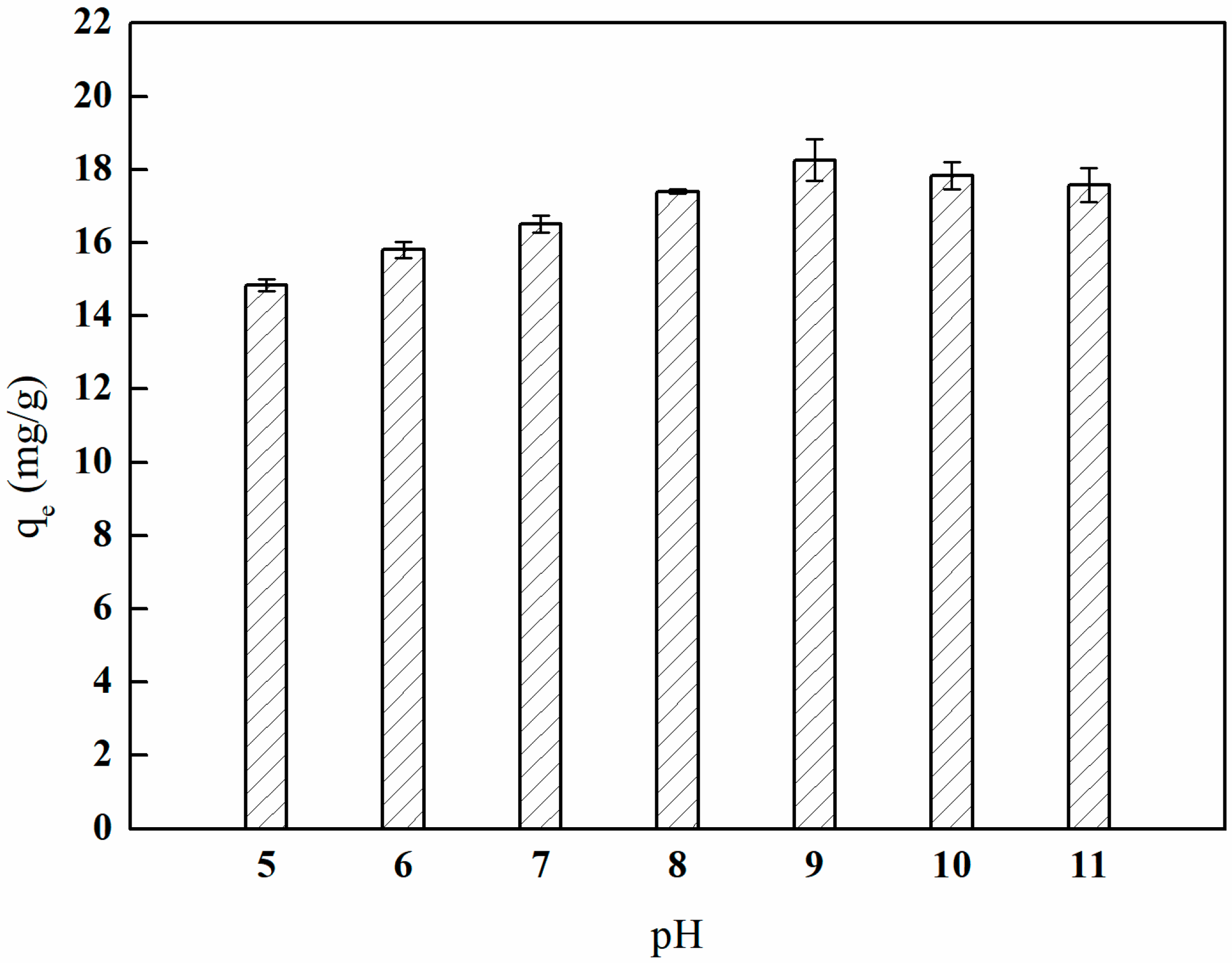
3.7.1. Adsorption Experiment with Different Solution pH Values
3.7.2. Adsorption Kinetics Experiment
3.7.3. Adsorption Isotherm
3.7.4. Adsorption Thermodynamics Experiment
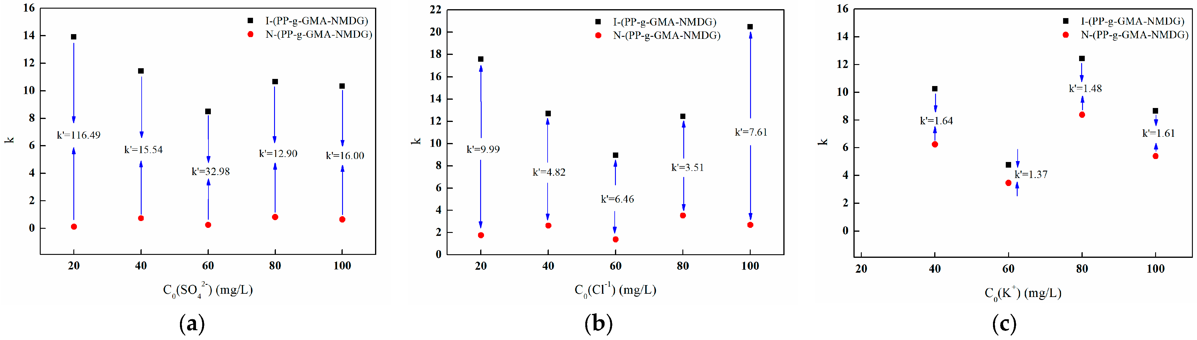
3.7.5. Adsorption Selectivity Experiment
3.8. Adsorption Mechanism of Borate Ions
3.9. Investigation of Reuse Performance
3.10. Characterization of the Imprinted Fibers Before and After Adsorption/Desorption
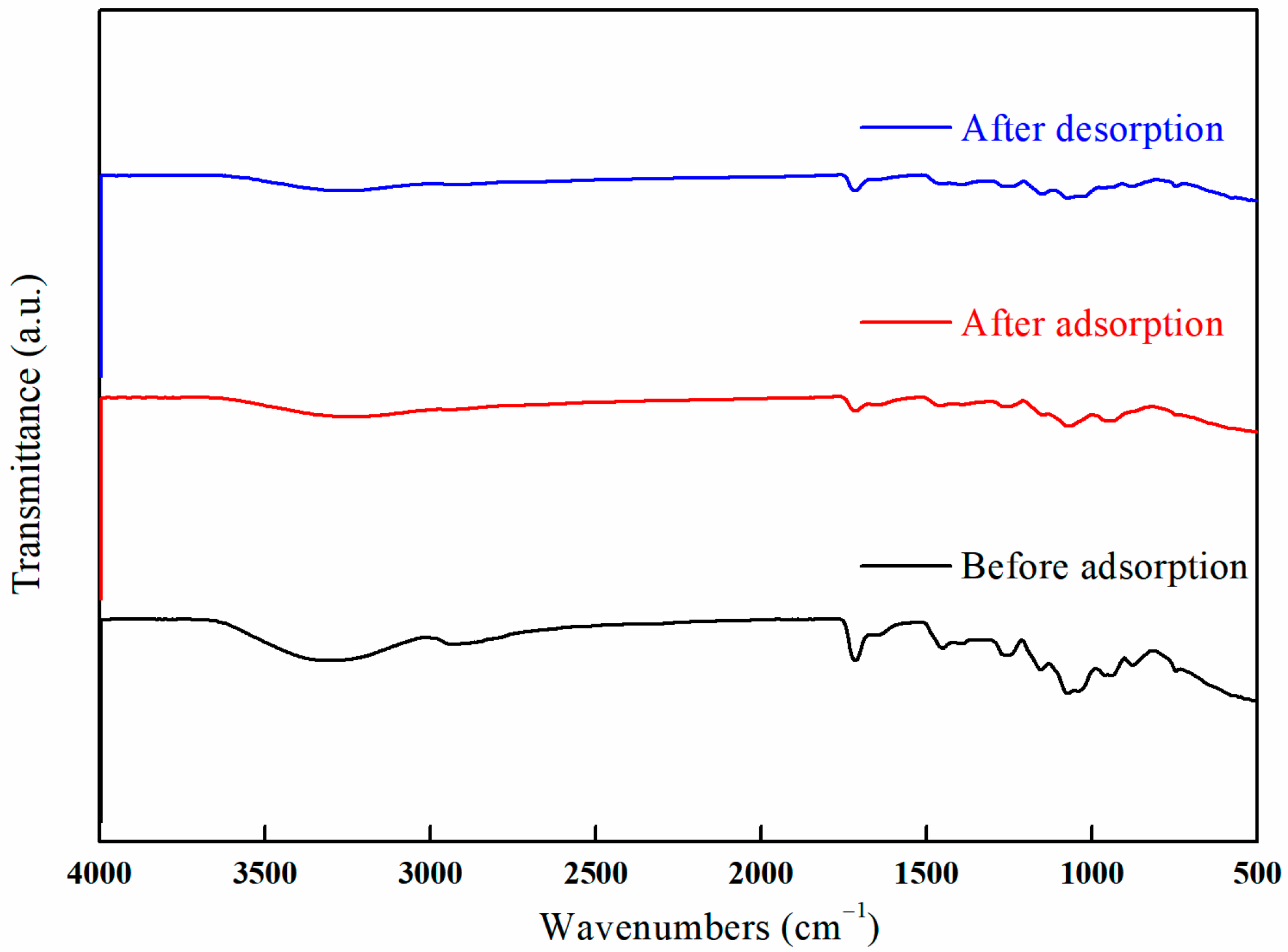
3.10.1. FT-IR
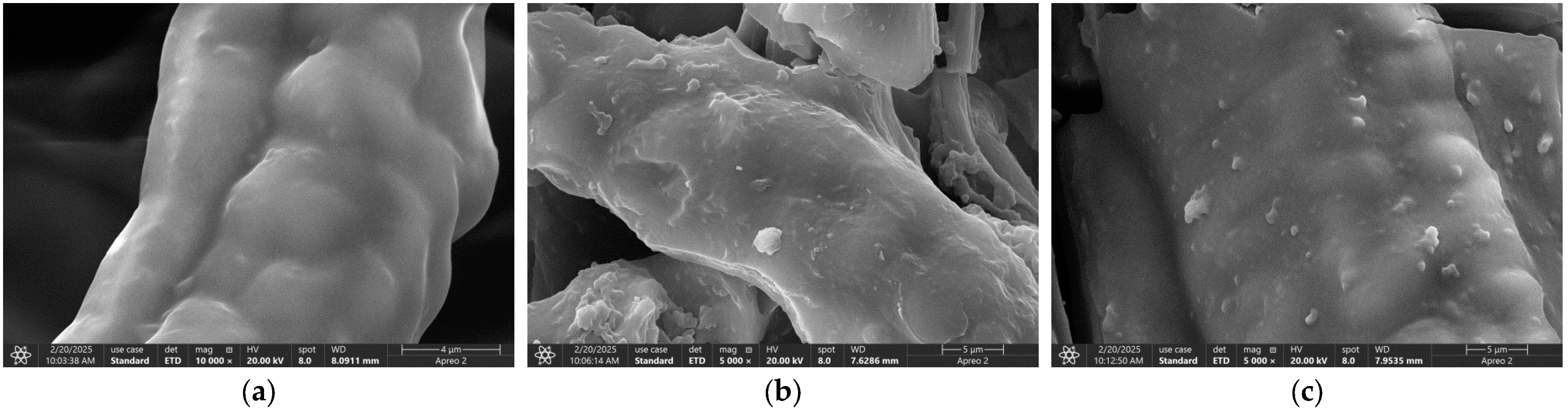
3.10.2. SEM
4. Conclusions
Author Contributions
Funding
Institutional Review Board Statement
Data Availability Statement
Conflicts of Interest
References
- Wolska, J.; Bryjak, M.; Koźlecki, T. Silica particles with N-methyl-D-glucamine for boron removal. Ion Exch. Lett. 2015, 8, 1–5. [Google Scholar]
- Schubert, D.M. Borates in Industrial Use; Springer: Berlin/Heidelberg, Germany, 2003; Volume 150, pp. 1–40. [Google Scholar]
- Hwang, S.D.; Byun, D.; Ianno, N.J.; Dowben, P.A.; Kim, H.R. Fabrication of boron-carbide/boron heterojunction devices. Appl. Phys. Lett. 1996, 68, 1495–1497. [Google Scholar] [CrossRef]
- Lin, C.T.; Chen, C.; Liu, H.Y. Boron prospecting based on boron cycling in subduction zone. Acta Petrol. Sin. 2020, 36, 5–12. [Google Scholar]
- Wu, Z.; Tai, G.; Shao, W.; Wang, R.; Hou, C. Experimental realization of quasicubic boron sheets. Nanoscale 2020, 12, 3787–3794. [Google Scholar] [CrossRef]
- Nasef, M.M.; Nallappan, M.; Ujang, Z. Polymer-based chelating adsorbents for the selective removal of boron from water and wastewater: A review. React. Funct. Polym. 2014, 85, 54–68. [Google Scholar] [CrossRef]
- Wu, Q.; Liu, M.; Wang, X. A novel chitosan based adsorbent for boron separation. Sep. Purif. Technol. 2019, 211, 162–169. [Google Scholar] [CrossRef]
- Kavak, D. Removal of boron from aqueous solutions by batch adsorption on calcined alunite using experimental design. J. Hazard. Mater. 2009, 163, 308–314. [Google Scholar] [CrossRef]
- Li, Z.; Ma, Y.H.; Yang, W.T. A Facile, Green, Versatile Protocol to Prepare Polypropylene-g-Poly(methyl methacrylate) Copolymer by Water-Solid Phase Suspension Grafting Polymerization Using the Surface of Reactor Granule Technology Polypropylene Granules as Reaction. J. Appl. Polym. Sci. 2013, 129, 3170–3177. [Google Scholar] [CrossRef]
- Wang, H.; Jin, X.Y.; Wu, H.B. Adsorption and Desorption Properties of Modified Feather and Feather/PP Melt-Blown Filter Cartridge of Lead Ion (Pb2+). J. Appl. Polym. Sci. 2014, 132, 41555–41562. [Google Scholar] [CrossRef]
- Salimi, A. Characterization of nano scale adhesion at solid surface of oxidized PP wax/PP blends. Int. J. Adhes. Adhes. 2012, 33, 61–66. [Google Scholar] [CrossRef]
- Biswajit, M.; Sabyasachi, M. Chemical modification of xanthan gum through graft copolymerization: Tailored properties and potential applications in drug delivery and wastewater treatment. Carbohydr. Polym. 2021, 251, 117095. [Google Scholar]
- Zhang, H.; Fang, D.; Kong, Z.; Wei, J.; Wu, X.; Shen, S.; Cui, W.; Zhu, Y. Enhanced adsorption of phthalic acid esters (PAEs) from aqueous solution by alkylbenzene-functionalized polypropylene nonwoven and its adsorption mechanism insight. Chem. Eng. J. 2018, 331, 406–415. [Google Scholar] [CrossRef]
- Zhou, Q.; Li, M.; Yao, X.; Lian, Z.; Zhang, C.; Wei, W.; Huang, J. Preparation of polypropylene chelating fibers by quenching pretreatment and suspension grafting and their Pb2+ adsorption ability. Fibers Polym. 2014, 15, 2238–2246. [Google Scholar] [CrossRef]
- Kong, C.; Kanezashi, M.; Yamomoto, T.; Shintani, T.; Tsuru, T. Controlled synthesis of high performance polyamide membrane with thin dense layer for water desalination. J. Membr. Sci. 2010, 362, 76–80. [Google Scholar] [CrossRef]
- Lau, W.J.; Ismail, A.F. Progress in interfacial polymerization technique on composite membrane preparation. In Proceedings of the 2011 2nd International Conference on Environmental Engineering and Applications (ICEEA 2011), Shanghai, China, 19–21 August 2011; pp. 586–588. [Google Scholar]
- Wang, T.; Liu, J.; Zhang, Y.S.; Zhang, H.C.; Chen, W.-Y.; Norris, P.; Pan, W.-P. Use of a non-thermal plasma technique to increase the number of chlorine active sites on biochar for improved mercury removal. Chem. Eng. J. 2018, 331, 536–544. [Google Scholar] [CrossRef]
- Li, D.; Xiong, M.; Wang, S.; Chen, X.; Wang, S.; Zeng, Q. Effects of low-temperature plasma treatment on wettability of glass surface: Molecular dynamic simulation and experimental study. Appl. Surf. Sci. 2020, 503, 144257. [Google Scholar] [CrossRef]
- Zhang, H.B.; Chen, Q. Recent progress of non-thermal plasma material surface treatment and functionalization. Acta Phys. Sin. 2021, 70, 095203–095217. [Google Scholar] [CrossRef]
- Yilma, B.B.; Luebben, J.F.; Nalankill, G. Cold Plasma Treatment in Wet Chemical Textile Processing. Fibres Text. East. Eur. 2020, 28, 118–126. [Google Scholar] [CrossRef]
- Smith, G.H.; Anderson, J.L. Solvent Polarity and Chemical Reactivity. J. Chem. Educ. 2015, 92, 1821–1828. [Google Scholar]
- Wang, Y.; Zhang, Y. Study on Grafting of Glycidyl Methacrylate onto Polymeric Substrates using Different Solvents. Polym. Int. 2018, 67, 309–318. [Google Scholar]
- Vendamme, R.; Eevers, W.; Kaneto, M.; Minamizaki, Y. Influence of Polymer Morphology on the Capacity of Molecularly Imprinted Resins to Release or to Retain their Template. Polym. J. 2009, 41, 1055–1066. [Google Scholar] [CrossRef]
- Yamaguchi, N.; Wang, J.S.; Hewitt, J.M.; Lenhart, W.C.; Mourey, T.H. Acid chloride-functionalized hyperbranched polyester for facile and quantitative chain-end modification: One-pot synthesis and structure characterization. J. Polym. Sci. Part A Polym. Chem. 2002, 40, 2855–2867. [Google Scholar] [CrossRef]
- Zhang, G.; Li, H.X.; Antensteiner, M.; Chung, T.C.M. Synthesis of Functional Polypropylene Containing Hindered Phenol Stabilizers and Applications in Metallized Polymer Film Capacitors. Macromolecules 2015, 48, 2925–2934. [Google Scholar] [CrossRef]
- Smith, J.; Johnson, K. Kinetics of graft copolymerization reactions. J. Polym. Sci. 2018, 56, 123–134. [Google Scholar]
- Wang, L.; Zhang, Y. Optimization of graft copolymerization conditions. Polym. Chem. 2020, 11, 567–578. [Google Scholar]
- Petruš, J.; Korčušková, M.; Kučera, F.; Jančář, J. Solid-state hydroxylation of polypropylene. Mater. Today Commun. 2022, 31, 103428. [Google Scholar] [CrossRef]
- Zhang, Y.; Ren, Y.L.; Liu, X.H.; Huo, T.G.; Qin, Y.W. Preparation of durable flame retardant PAN fabrics based on amidoximation and phosphorylation. Appl. Surf. Sci. 2018, 428, 395–403. [Google Scholar] [CrossRef]
- Sokker, H.H.; Badawy, S.M.; Zayed, E.M.; Eldien, F.; Farag, A.M. Radiation-induced grafting of glycidyl methacrylate onto cotton fabric waste and its modification for anchoring hazardous wastes from their solutions. J. Hazard. Mater. 2009, 168, 137–144. [Google Scholar] [CrossRef]
- Monier, M.; Kenawy, I.M.; Hashem, M.A. Synthesis and characterization of selective thiourea modified Hg(II) ion-imprinted cellulosic cotton fibers. Carbohydr. Polym. 2014, 106, 49–59. [Google Scholar] [CrossRef]
- Monier, M.; Ibrahim, A.A.; Metwally, M.M.; Badawy, D.S. Surface ion-imprinted amino-functionalized cellulosic cotton fibers for selective extraction of Cu(II) ions. Int. J. Biol. Macromol. 2015, 81, 736–746. [Google Scholar] [CrossRef]
- Zhu, F.; Li, L.; Xing, J. Selective adsorption behavior of Cd(II) ion imprinted polymers synthesized by microwave-assisted inverse emulsion polymerization: Adsorption performance and mechanism. J. Hazard. Mater. 2017, 321, 103–110. [Google Scholar] [CrossRef] [PubMed]
- Liu, H.N.; Qing, B.J.; Ye, X.S.; Li, Q.; Lee, K.; Wu, Z.J. Boron adsorption by composite magnetic particles. Chem. Eng. J. 2009, 151, 235–240. [Google Scholar] [CrossRef]
- Nishihama, S.; Sumiyoshi, Y.; Ookubo, T.; Yoshizuka, K. Adsorption of boron using glucamine-based chelate adsorbents. Desalination 2013, 310, 81–86. [Google Scholar] [CrossRef]
- Chashmejahanbin, M.R.; Daemi, H.; Barikani, M.; Salimi, A. Noteworthy impacts of polyurethane-urea ionomers as the efficient polar coatings on adhesion strength of plasma treated polypropylene. Appl. Surf. Sci. 2014, 317, 688–695. [Google Scholar] [CrossRef]
- Shek, T.H.; Ma, A.; Lee, V.; Mckay, G. Kinetics of zinc ions removal from effluents using ion exchange resin. Chem. Eng. J. 2009, 146, 63–70. [Google Scholar] [CrossRef]
- Liu, H.N.; Ye, X.S.; Li, Q.; Kim, T.; Qing, B.J.; Guo, M.; Ge, F.; Wu, Z.J.; Lee, K. Boron adsorption using a new boron-selective hybrid gel and the commercial resin D564. Colloids Surf. A Physicochem. Eng. Asp. 2009, 341, 118–126. [Google Scholar] [CrossRef]
- Jung, J.; Choi, H.; Hong, S.; Yoon, S.J.; Kim, T.-H.; Lee, J.Y.; Hong, Y.T.; So, S. Surface-initiated ATRP of Glycidyl Methacrylate in the Presence of Divinylbenzene on Porous Polystyrene-based Resins for Boron Adsorption. Desalination 2020, 473, 114166. [Google Scholar] [CrossRef]
- Wang, J.; Bao, Z.; Xing, H.; Su, B.; Zhang, Z.; Yang, Q.; Yang, Y.; Ren, Q.; Chen, B. Incorporation of N-Methyl-dglucamine Functionalized Oligomer into MIL-101(Cr) for Highly Efficient Removal of Boric Acid from Water. Chem. A Eur. J. 2016, 22, 15290–15297. [Google Scholar] [CrossRef]
- Lu, X.; Liu, Y.; Hu, H.; Wu, Z.; Chen, Q. Synthesis, characterization and application of a novel silica based adsorbent for boron removal. Desalination 2012, 294, 1–7. [Google Scholar]
- Kamcev, J.; Taylor, M.K.; Shin, D.M.; Jarenwattananon, N.N.; Colwell, K.A.; Long, J.R. Functionalized Porous Aromatic Frameworks as High-Performance Adsorbents for the Rapid Removal of Boric Acid from Water. Adv. Mater. 2019, 31, e1808027. [Google Scholar] [CrossRef]
- Bicak, N.; Gazi, M.; Bahire, F.S. Polymer supported amino bis(cis-propan 2,3 diol) functions for removal of trace boron from water. React. Funct. Polym. 2005, 65, 143–148. [Google Scholar] [CrossRef]
- Eljamal, O.; Maamoun, I.; Alkhudhayri, S.; Eljamal, R.; Falyouna, O.; Tanaka, K.; Kozai, N.; Sugihara, Y. Insights into boron removal from water using Mg-Al-LDH: Reaction parameters optimization & 3D-RSM modeling. J. Water Process Eng. 2022, 46, 102608. [Google Scholar]
- Liu, H.; Kong, D.L.; Sun, W.; Li, Q.S.; Zhou, Z.Y.; Ren, Z.Q. Effect of anions on the polymerization and adsorption processes of Cu(II) ion-imprinted polymers. Chem. Eng. J. 2016, 303, 348–358. [Google Scholar] [CrossRef]


| Factor | Code | Encoding Level | ||
|---|---|---|---|---|
| −1 | 0 | 1 | ||
| GMA concentration/% | A | 20 | 25 | 30 |
| Temperature/°C | B | 75 | 80 | 85 |
| Time/h | C | 1.5 | 2 | 2.5 |
| Experiment Number | A | B | C | GP (%) |
|---|---|---|---|---|
| 1 | 25 | 80 | 2 | 157.24 |
| 2 | 20 | 85 | 2 | 106.81 |
| 3 | 30 | 85 | 2 | 160.32 |
| 4 | 20 | 80 | 1.5 | 100.19 |
| 5 | 30 | 80 | 1.5 | 121.71 |
| 6 | 30 | 75 | 2 | 147.45 |
| 7 | 25 | 75 | 2.5 | 181.36 |
| 8 | 20 | 75 | 2 | 106.45 |
| 9 | 30 | 80 | 2.5 | 171.68 |
| 10 | 25 | 85 | 1.5 | 104.65 |
| 11 | 20 | 80 | 2.5 | 172.52 |
| 12 | 25 | 80 | 2 | 152.67 |
| 13 | 25 | 80 | 2 | 131.2 |
| 14 | 25 | 75 | 1.5 | 95.53 |
| 15 | 25 | 80 | 2 | 141.19 |
| 16 | 25 | 80 | 2 | 131.58 |
| 17 | 25 | 85 | 2.5 | 209.3 |
| Source | Sum of Squares | df | Mean Square | F-Value | p-Value | |
|---|---|---|---|---|---|---|
| Model | 14,345.96 | 9 | 1594 | 7.16 | 0.0083 | significant |
| A-GMA Concentration | 1714.93 | 1 | 1714.93 | 7.70 | 0.0275 | |
| B-Temperature | 397.76 | 1 | 397.76 | 1.79 | 0.2231 | |
| C-Time | 11,590.03 | 1 | 11,590.03 | 52.06 | 0.0002 | |
| AB | 1.54 | 1 | 1.54 | 0.0069 | 0.9361 | |
| AC | 61.70 | 1 | 61.70 | 0.2772 | 0.6148 | |
| BC | 158.38 | 1 | 158.38 | 0.7115 | 0.4268 | |
| A2 | 278.78 | 1 | 278.78 | 1.25 | 0.3000 | |
| B2 | 29.61 | 1 | 29.61 | 0.1330 | 0.7261 | |
| C2 | 128.55 | 1 | 128.55 | 0.5775 | 0.4721 | |
| Residual | 1558.28 | 7 | 222.61 | |||
| Lack of Fit | 1167.75 | 3 | 389.25 | 3.99 | 0.1074 | not significant |
| Pure Error | 390.53 | 4 | 97.63 | |||
| Cor Total | 15,904.24 | 16 |
| qe,experiment (mg/g) | Pseudo-First-Order Model | Pseudo-Second-Order Model | ||||
|---|---|---|---|---|---|---|
| qe (mg/g) | k1 (min−1) | R2 | qe (mg/g) | k2 (g/mg·min) | R2 | |
| 18.26 | 16.77 | 0.0392 | 0.9798 | 21.06 | 0.0029 | 0.9968 |
| T (°C) | Langmuir | Freundlich | Temkin | ||||||
|---|---|---|---|---|---|---|---|---|---|
| qm | KL | R2 | n | KF | R2 | BT | KT | R2 | |
| 25 | 39.05 | 0.0095 | 0.9517 | 2.1986 | 2.1129 | 0.9909 | 10.0508 | 0.0627 | 0.9717 |
| 30 | 24.06 | 0.0224 | 0.9170 | 3.7015 | 4.394 | 0.9945 | 4.8014 | 0.2580 | 0.9762 |
| 35 | 18.83 | 0.0335 | 0.9408 | 5.1840 | 5.5864 | 0.9941 | 2.8902 | 1.1672 | 0.9936 |
| Adsorbents | Substrate Material | qe (mg/g) | References |
|---|---|---|---|
| Commercial resin D564 | 15.78 | [38] | |
| PGMA–PS-NMDG | PGMA-PS | 21.66 | [39] |
| CTS-NMDG | CCTS | 20.36 | [7] |
| Poly(Si-NMDG)@MIL-101(Cr) | MIL-101 | 24.80 | [40] |
| Si-NMDG | SiO2 | 16.68 | [41] |
| PAF-1-NMDG | PAF-1 | 17.51 | [42] |
| CCTS-IBPG | CCTS | 29.19 | [43] |
| Mg-Al-CLDH | 22.1 | [44] | |
| I-(PP-g-GMA-NMDG) | PP | 35.85 | This work |
| T (°C) | ∆G0 (kJ/mol) | ∆H0 (kJ/mol) | ∆S0 (kJ/mol·K) |
|---|---|---|---|
| 25 | 3.615 | −8.796 | −0.0416 |
| 30 | 3.766 | −0.0414 | |
| 35 | 4.032 | −0.0416 |
Disclaimer/Publisher’s Note: The statements, opinions and data contained in all publications are solely those of the individual author(s) and contributor(s) and not of MDPI and/or the editor(s). MDPI and/or the editor(s) disclaim responsibility for any injury to people or property resulting from any ideas, methods, instructions or products referred to in the content. |
© 2025 by the authors. Licensee MDPI, Basel, Switzerland. This article is an open access article distributed under the terms and conditions of the Creative Commons Attribution (CC BY) license (https://creativecommons.org/licenses/by/4.0/).
Share and Cite
Jiang, H.; Zong, X.; Luo, Z.; Geng, W.; Zhu, J. Surface Ion-Imprinted Polypropylene Fibers for Selective and Rapid Adsorption of Borate Ions: Preparation, Characterization, and Performance Study. Polymers 2025, 17, 1368. https://doi.org/10.3390/polym17101368
Jiang H, Zong X, Luo Z, Geng W, Zhu J. Surface Ion-Imprinted Polypropylene Fibers for Selective and Rapid Adsorption of Borate Ions: Preparation, Characterization, and Performance Study. Polymers. 2025; 17(10):1368. https://doi.org/10.3390/polym17101368
Chicago/Turabian StyleJiang, Hui, Xinchi Zong, Zhengwei Luo, Wenhua Geng, and Jianliang Zhu. 2025. "Surface Ion-Imprinted Polypropylene Fibers for Selective and Rapid Adsorption of Borate Ions: Preparation, Characterization, and Performance Study" Polymers 17, no. 10: 1368. https://doi.org/10.3390/polym17101368
APA StyleJiang, H., Zong, X., Luo, Z., Geng, W., & Zhu, J. (2025). Surface Ion-Imprinted Polypropylene Fibers for Selective and Rapid Adsorption of Borate Ions: Preparation, Characterization, and Performance Study. Polymers, 17(10), 1368. https://doi.org/10.3390/polym17101368