Iridium and Ruthenium Modified Polyaniline Polymer Leads to Nanostructured Electrocatalysts with High Performance Regarding Water Splitting

 , , ,
, , ,  and
and 
Abstract
1. Introduction
2. Experimental
2.1. Materials and Chemicals
2.2. Synthesis of Polyaniline-Based Ruthenium and Iridium Materials
2.3. Physicochemical Characterization
2.4. Electrochemical and Electrocatalytic Measurements
3. Results and Discussion
3.1. Physicochemical Characterization of the Materials
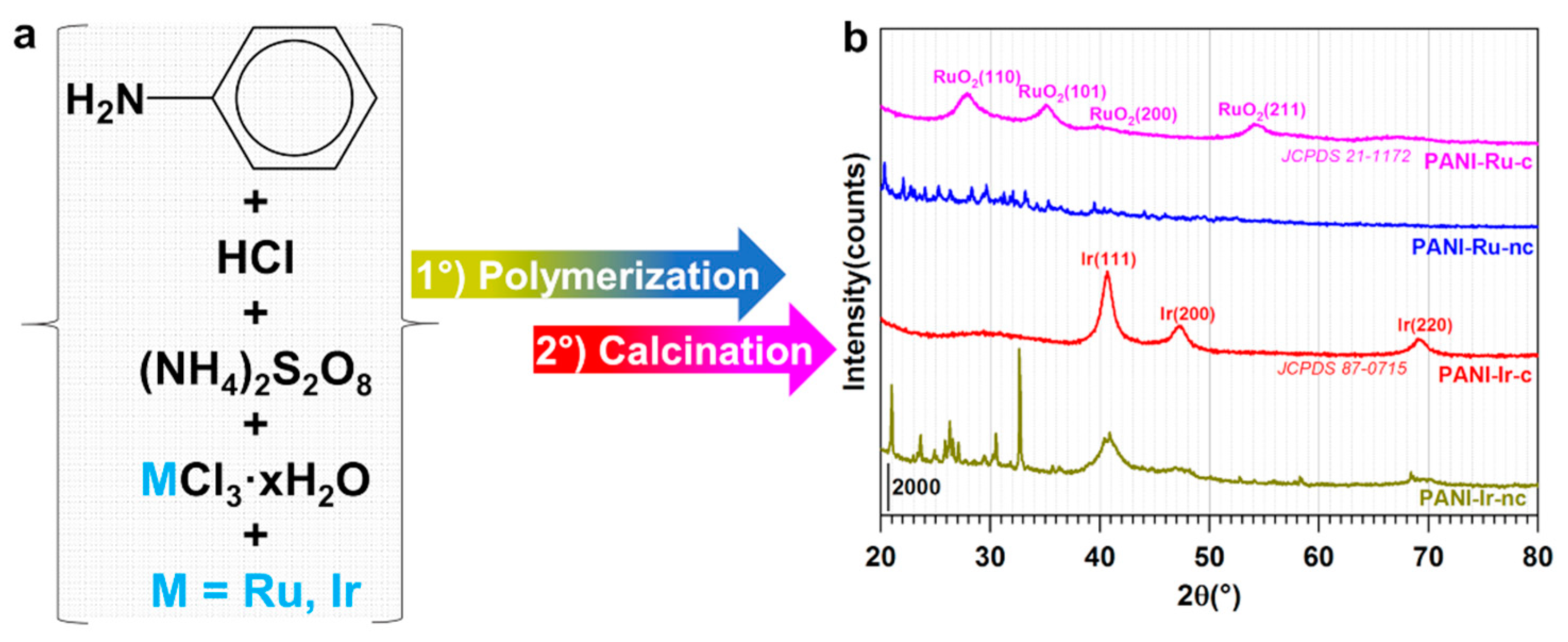
3.1.1. XRD Analysis
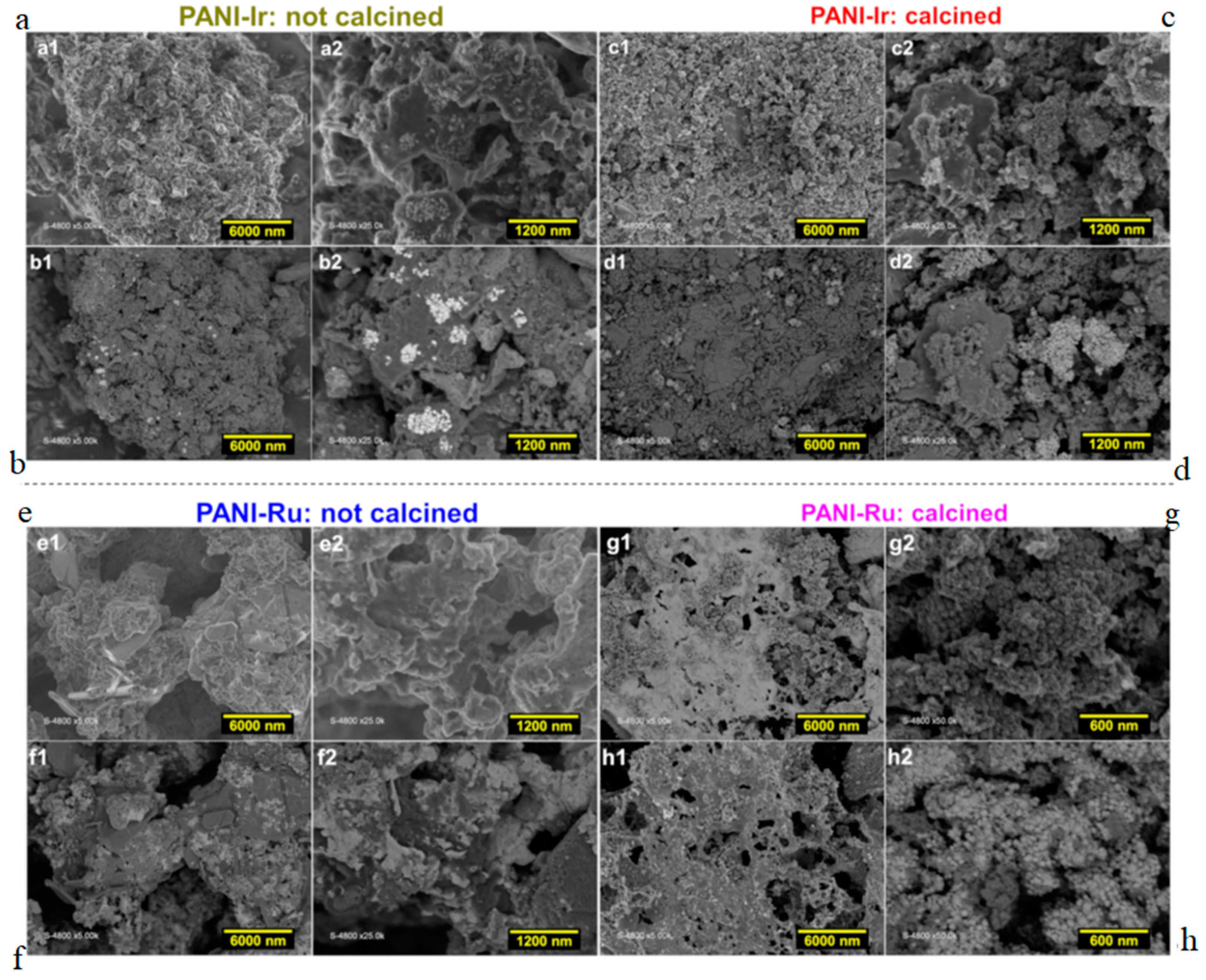
3.1.2. SEM Analysis
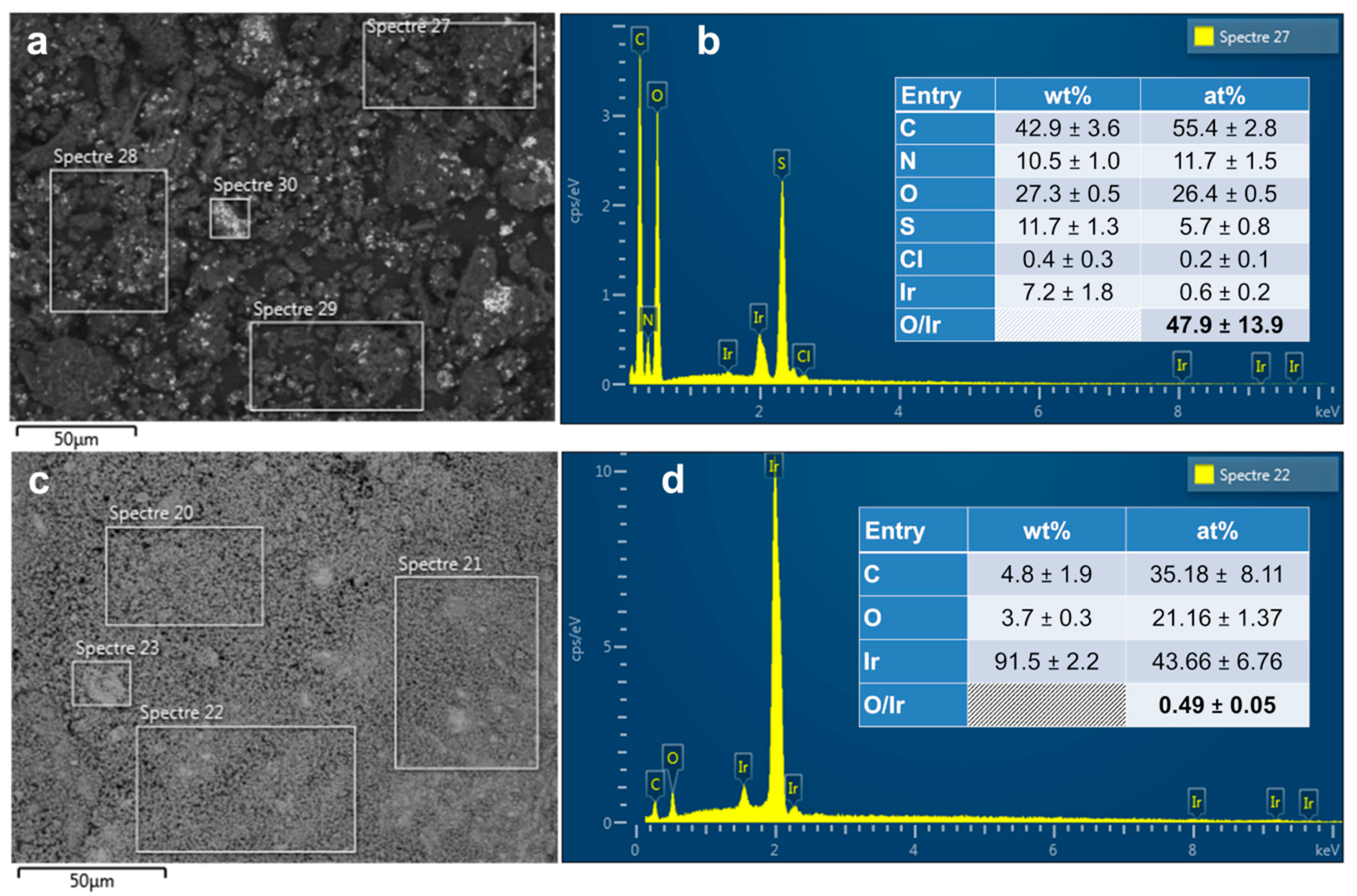
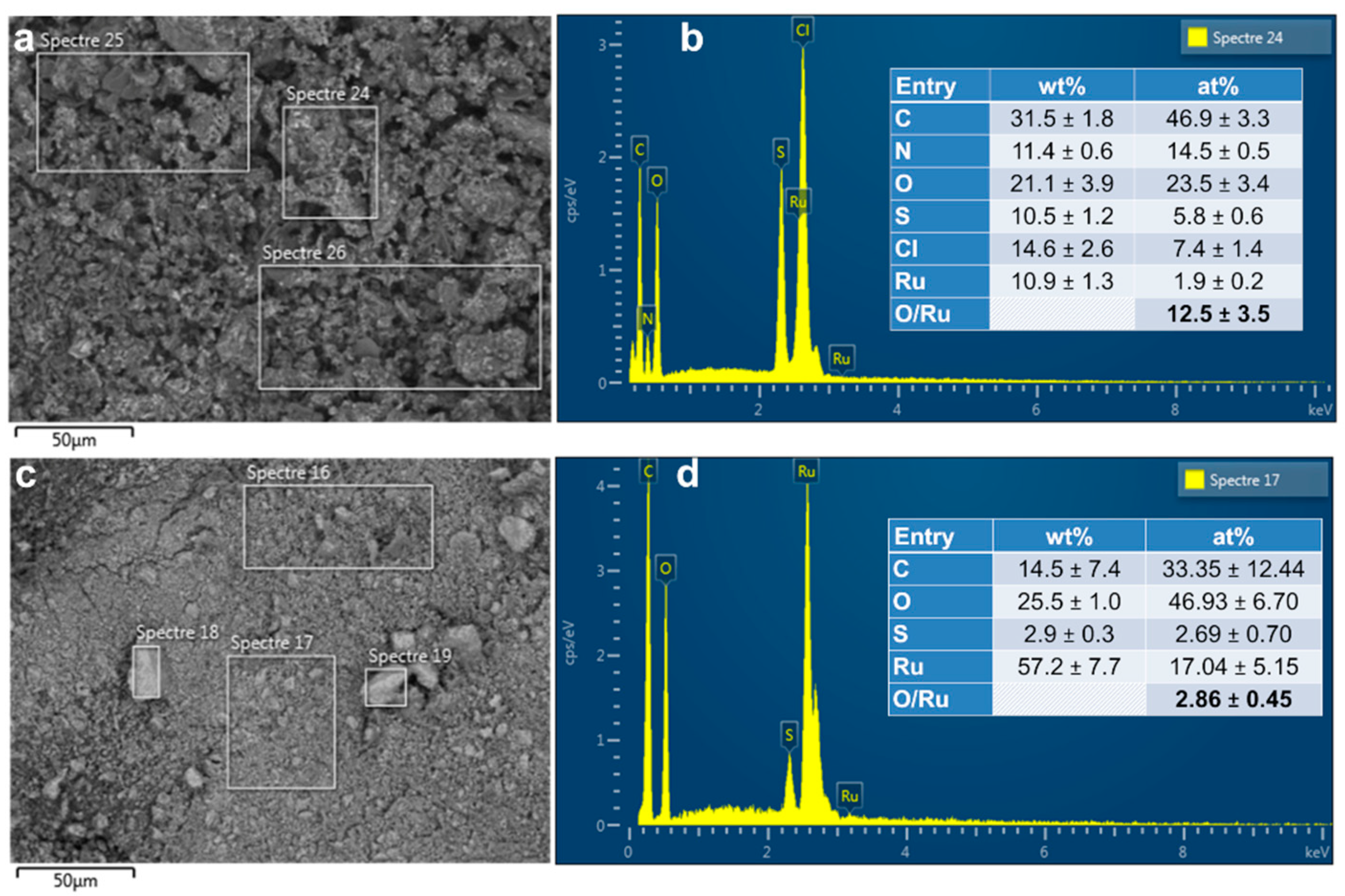
3.1.3. EDX Analysis
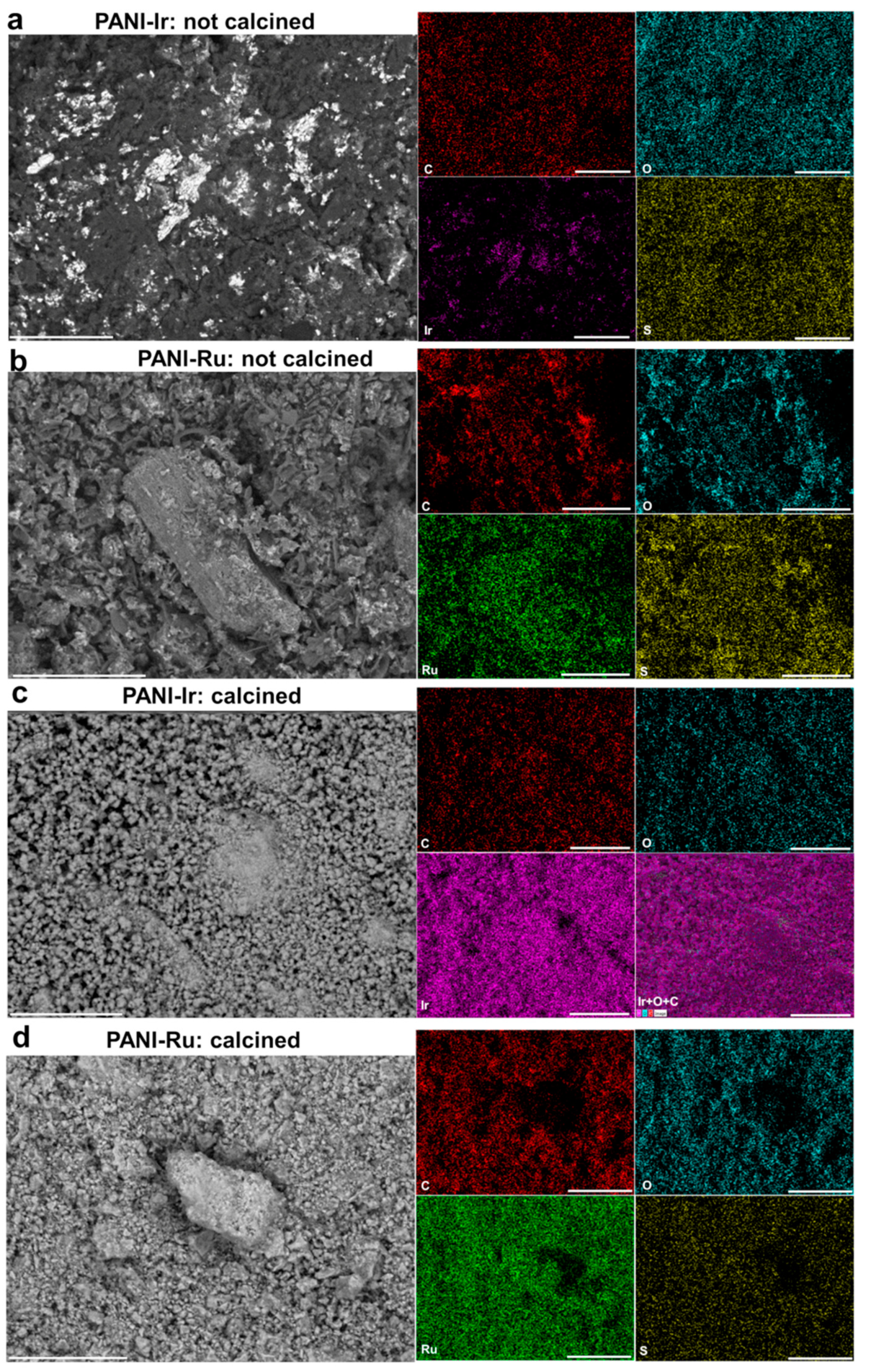
3.1.4. EDX Mapping
3.2. Electrochemical Performance
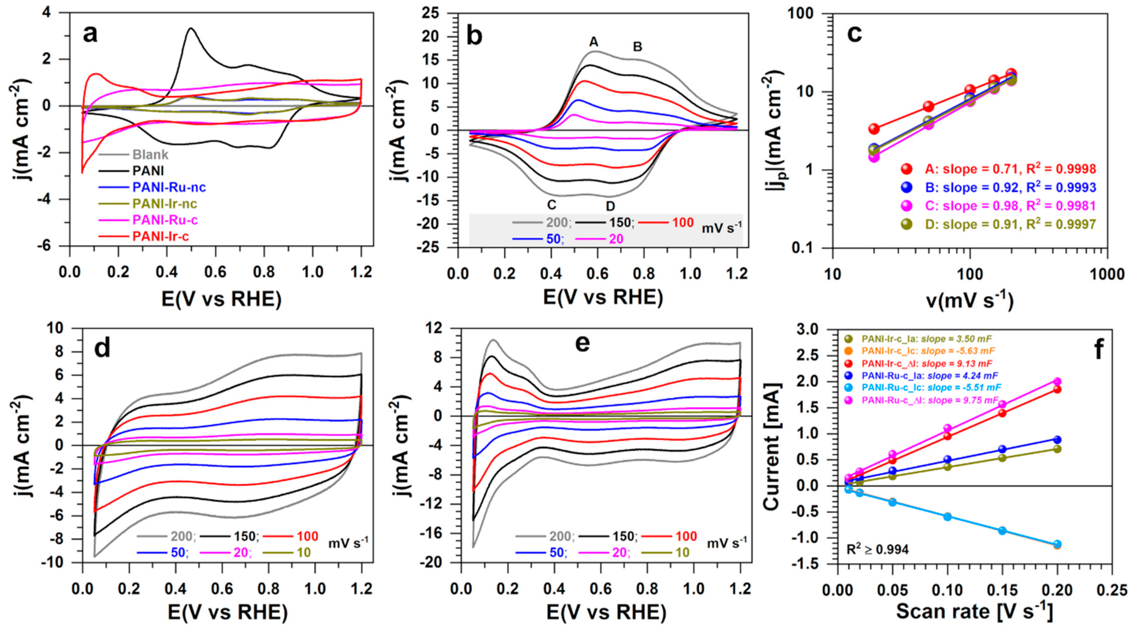
3.2.1. Electrochemical Characterization
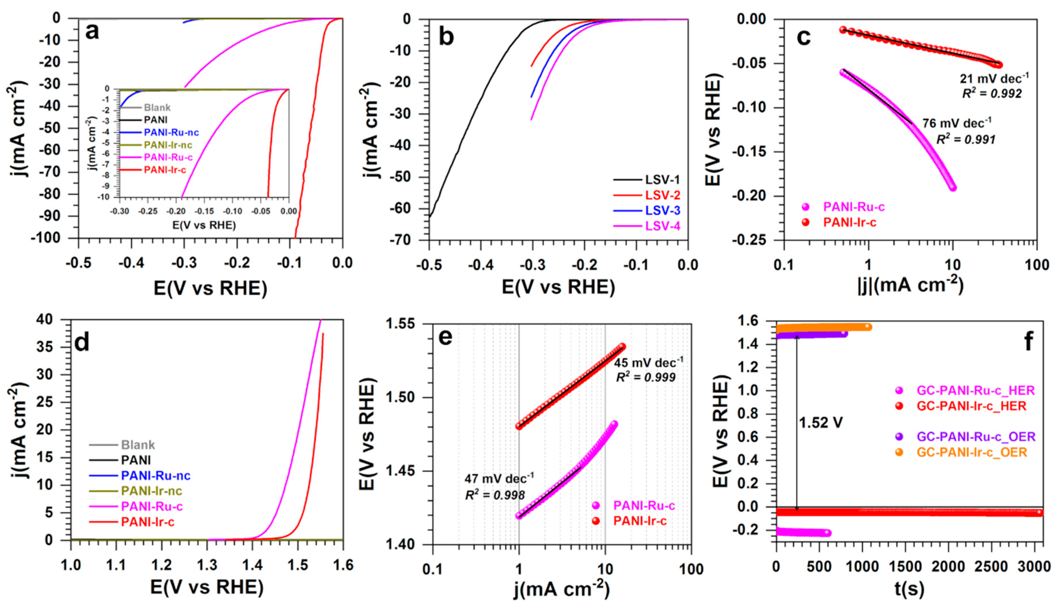
3.2.2. Half-Cell Performance Regarding Hydrogen Evolution Reaction and Oxygen Evolution Reaction
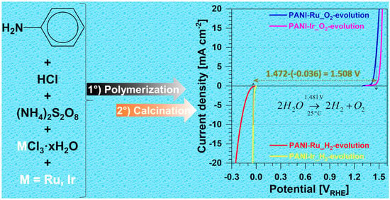
3.2.3. Overall Water Splitting
4. Conclusions
Author Contributions
Funding
Institutional Review Board Statement
Informed Consent Statement
Data Availability Statement
Acknowledgments
Conflicts of Interest
References
- Chung, D.Y.; Park, S.; Lopes, P.P.; Stamenkovic, V.R.; Sung, Y.-E.; Markovic, N.M.; Strmcnik, D. Electrokinetic Analysis of Poorly Conductive Electrocatalytic Materials. ACS Catal. 2020, 10, 4990–4996. [Google Scholar] [CrossRef]
- Djara, R.; Masquelez, N.; Lacour, M.-A.; Merzouki, A.; Cambedouzou, J.; Cornu, D.; Tingry, S.; Holade, Y. Self-Supported Electrocatalysts Derived from Nickel-Cobalt Modified Polyaniline Polymer for H2-Evolution and O2-Evolution Reactions. ChemCatChem 2020, 12, 5789–5796. [Google Scholar] [CrossRef]
- Djara, R.; Holade, Y.; Merzouki, A.; Lacour, M.-A.; Masquelez, N.; Flaud, V.; Cot, D.; Rebiere, B.; van der Lee, A.; Cambedouzou, J.; et al. Nanostructured Carbon-Nitrogen-Sulfur-Nickel Networks Derived From Polyaniline as Bifunctional Catalysts for Water Splitting. Front. Chem. 2020, 8, 385. [Google Scholar] [CrossRef]
- Xu, S.; Minteer, S.D. Pyrroloquinoline Quinone-Dependent Enzymatic Bioanode: Incorporation of the Substituted Polyaniline Conducting Polymer as a Mediator. ACS Catal. 2014, 4, 2241–2248. [Google Scholar] [CrossRef]
- Ghosh, S.; Bera, S.; Bysakh, S.; Basu, R.N. Conducting polymer nanofiber-supported Pt alloys: Unprecedented materials for methanol oxidation with enhanced electrocatalytic performance and stability. Sustain. Energy Fuels 2017, 1, 1148–1161. [Google Scholar] [CrossRef]
- Ghosh, S.; Bera, S.; Bysakh, S.; Basu, R.N. Highly Active Multimetallic Palladium Nanoalloys Embedded in Conducting Polymer as Anode Catalyst for Electrooxidation of Ethanol. ACS Appl. Mater. Interfaces 2017, 9, 33775–33790. [Google Scholar] [CrossRef] [PubMed]
- Song, F.; Li, W.; Han, G.; Sun, Y. Electropolymerization of Aniline on Nickel-Based Electrocatalysts Substantially Enhances Their Performance for Hydrogen Evolution. ACS Appl. Energy Mater. 2018, 1, 3–8. [Google Scholar] [CrossRef]
- Feng, J.-X.; Tong, S.-Y.; Tong, Y.-X.; Li, G.-R. Pt-like Hydrogen Evolution Electrocatalysis on PANI/CoP Hybrid Nanowires by Weakening the Shackles of Hydrogen Ions on the Surfaces of Catalysts. J. Am. Chem. Soc. 2018, 140, 5118–5126. [Google Scholar] [CrossRef] [PubMed]
- Kokoh, K.B.; Mayousse, E.; Napporn, T.W.; Servat, K.; Guillet, N.; Soyez, E.; Grosjean, A.; Rakotondrainibé, A.; Paul-Joseph, J. Efficient multi-metallic anode catalysts in a PEM water electrolyzer. Int. J. Hydrog. Energy 2014, 39, 1924–1931. [Google Scholar] [CrossRef]
- Audichon, T.; Napporn, T.W.; Canaff, C.; Morais, C.; Comminges, C.; Kokoh, K.B. IrO2 Coated on RuO2 as Efficient and Stable Electroactive Nanocatalysts for Electrochemical Water Splitting. J. Phys. Chem. C 2016, 120, 2562–2573. [Google Scholar] [CrossRef]
- Oh, H.-S.; Nong, H.N.; Reier, T.; Gliech, M.; Strasser, P. Oxide-supported Ir nanodendrites with high activity and durability for the oxygen evolution reaction in acid PEM water electrolyzers. Chem. Sci. 2015, 6, 3321–3328. [Google Scholar] [CrossRef] [PubMed]
- Wang, H.; Abruña, H.D. Rh and Rh Alloy Nanoparticles as Highly Active H2 Oxidation Catalysts for Alkaline Fuel Cells. ACS Catal. 2019, 9, 5057–5062. [Google Scholar] [CrossRef]
- Zheng, J.; Sheng, W.; Zhuang, Z.; Xu, B.; Yan, Y. Universal dependence of hydrogen oxidation and evolution reaction activity of platinum-group metals on pH and hydrogen binding energy. Sci. Adv. 2016, 2, e1501602. [Google Scholar] [CrossRef] [PubMed]
- Patra, B.C.; Khilari, S.; Manna, R.N.; Mondal, S.; Pradhan, D.; Pradhan, A.; Bhaumik, A. A Metal-Free Covalent Organic Polymer for Electrocatalytic Hydrogen Evolution. ACS Catal. 2017, 7, 6120–6127. [Google Scholar] [CrossRef]
- Jena, H.S.; Krishnaraj, C.; Parwaiz, S.; Lecoeuvre, F.; Schmidt, J.; Pradhan, D.; Van Der Voort, P. Illustrating the Role of Quaternary-N of BINOL Covalent Triazine-Based Frameworks in Oxygen Reduction and Hydrogen Evolution Reactions. ACS Appl. Mater. Interfaces 2020, 12, 44689–44699. [Google Scholar] [CrossRef]
- Roger, I.; Shipman, M.A.; Symes, M.D. Earth-abundant catalysts for electrochemical and photoelectrochemical water splitting. Nat. Rev. Chem. 2017, 1, Article number: 0003. [Google Scholar] [CrossRef]
- Zhao, T.; Hu, Y.; Gong, M.; Lin, R.; Deng, S.; Lu, Y.; Liu, X.; Chen, Y.; Shen, T.; Hu, Y.; et al. Electronic structure and oxophilicity optimization of mono-layer Pt for efficient electrocatalysis. Nano Energy 2020, 74, 104877. [Google Scholar] [CrossRef]
- Strmcnik, D.; Uchimura, M.; Wang, C.; Subbaraman, R.; Danilovic, N.; van der Vilet, D.; Paulikas, A.P.; Stamenkovic, V.R.; Markovic, N.M. Improving the hydrogen oxidation reaction rate by promotion of hydroxyl adsorption. Nat. Chem. 2013, 5, 300–306. [Google Scholar] [CrossRef]
- Ma, J.; Wang, M.; Lei, G.; Zhang, G.; Zhang, F.; Peng, W.; Fan, X.; Li, Y. Polyaniline Derived N-Doped Carbon-Coated Cobalt Phosphide Nanoparticles Deposited on N-Doped Graphene as an Efficient Electrocatalyst for Hydrogen Evolution Reaction. Small 2018, 14, 1702895. [Google Scholar] [CrossRef]
- Zhang, J.; Meng, X.; Zhao, J.; Zhu, Z. Construction of a MoxC/Ni Network Electrode with Low Overpotential for Hydrogen Generation. ChemCatChem 2014, 6, 2059–2064. [Google Scholar] [CrossRef]
- Djara, R.; Holade, Y.; Merzouki, A.; Masquelez, N.; Cot, D.; Rebiere, B.; Petit, E.; Huguet, P.; Canaff, C.; Morisset, S.; et al. Insights from the Physicochemical and Electrochemical Screening of the Potentiality of the Chemically Synthesized Polyaniline. J. Electrochem. Soc. 2020, 167, 066503. [Google Scholar] [CrossRef]
- Audichon, T.; Mayousse, E.; Morisset, S.; Morais, C.; Comminges, C.; Napporn, T.W.; Kokoh, K.B. Electroactivity of RuO2–IrO2 mixed nanocatalysts toward the oxygen evolution reaction in a water electrolyzer supplied by a solar profile. Int. J. Hydrog. Energy 2014, 39, 16785–16796. [Google Scholar] [CrossRef]
- Audichon, T.; Mayousse, E.; Napporn, T.W.; Morais, C.; Comminges, C.; Kokoh, K.B. Elaboration and characterization of ruthenium nano-oxides for the oxygen evolution reaction in a Proton Exchange Membrane Water Electrolyzer supplied by a solar profile. Electrochim. Acta 2014, 132, 284–291. [Google Scholar] [CrossRef]
- Mamaca, N.; Mayousse, E.; Arrii-Clacens, S.; Napporn, T.W.; Servat, K.; Guillet, N.; Kokoh, K.B. Electrochemical activity of ruthenium and iridium based catalysts for oxygen evolution reaction. Appl. Catal. B Environ. 2012, 111–112, 376–380. [Google Scholar] [CrossRef]
- Hammer, B.; Norskov, J.K. Why gold is the noblest of all the metals. Nature 1995, 376, 238–240. [Google Scholar] [CrossRef]
- Eckermann, A.L.; Feld, D.J.; Shaw, J.A.; Meade, T.J. Electrochemistry of redox-active self-assembled monolayers. Coord. Chem. Rev. 2010, 254, 1769–1802. [Google Scholar] [CrossRef]
- Liu, B.; Bard, A.J.; Mirkin, M.V.; Creager, S.E. Electron Transfer at Self-Assembled Monolayers Measured by Scanning Electrochemical Microscopy. J. Am. Chem. Soc. 2004, 126, 1485–1492. [Google Scholar] [CrossRef]
- Xing, J.; Liao, M.; Zhang, C.; Yin, M.; Li, D.; Song, Y. The effect of anions on the electrochemical properties of polyaniline for supercapacitors. Phys. Chem. Chem. Phys. 2017, 19, 14030–14041. [Google Scholar] [CrossRef]
- Sk, M.M.; Yue, C.Y.; Jena, R.K. Facile growth of heparin-controlled porous polyaniline nanofiber networks and their application in supercapacitors. RSC Adv. 2014, 4, 5188–5197. [Google Scholar] [CrossRef]
- Shah, A.-u.-H.A.; Kamran, M.; Bilal, S.; Ullah, R. Cost Effective Chemical Oxidative Synthesis of Soluble and Electroactive Polyaniline Salt and Its Application as Anticorrosive Agent for Steel. Materials 2019, 12, 1527. [Google Scholar] [CrossRef]
- Canales, M.; Torras, J.; Fabregat, G.; Meneguzzi, A.; Alemán, C. Polyaniline emeraldine salt in the amorphous solid state: Polaron versus bipolaron. J. Phys. Chem. B 2014, 118, 11552–11562. [Google Scholar] [CrossRef]
- Casanovas, J.; Canales, M.; Ferreira, C.A.; Alemán, C. A first principle analysis of the structure of oligoanilines doped with alkylsulfonic acids. J. Phys. Chem. A 2009, 113, 8795–8800. [Google Scholar] [CrossRef] [PubMed]
- Parpot, P.; Kokoh, K.B.; Beden, B.; Lamy, C. Electrocatalytic oxidation of saccharose in alkaline medium. Electrochim. Acta 1993, 38, 1679–1683. [Google Scholar] [CrossRef]
- Woods, R. Hydrogen adsorption on platinum, iridium and rhodium electrodes at reduced temperatures and the determination of real surface area. J. Electroanal. Chem. Interfacial Electrochem. 1974, 49, 217–226. [Google Scholar] [CrossRef]
- Fierro, S.; Kapałka, A.; Comninellis, C. Electrochemical comparison between IrO2 prepared by thermal treatment of iridium metal and IrO2 prepared by thermal decomposition of H2IrCl6 solution. Electrochem. Commun. 2010, 12, 172–174. [Google Scholar] [CrossRef]
- Chen, G.; Chen, X.; Yue, P.L. Electrochemical Behavior of Novel Ti/IrOx−Sb2O5−SnO2 Anodes. J. Phys. Chem. B 2002, 106, 4364–4369. [Google Scholar] [CrossRef]
- McCrory, C.C.L.; Jung, S.; Peters, J.C.; Jaramillo, T.F. Benchmarking Heterogeneous Electrocatalysts for the Oxygen Evolution Reaction. J. Am. Chem. Soc. 2013, 135, 16977–16987. [Google Scholar] [CrossRef]
- Li, M.; Wang, H.; Zhu, W.; Li, W.; Wang, C.; Lu, X. RuNi Nanoparticles Embedded in N-Doped Carbon Nanofibers as a Robust Bifunctional Catalyst for Efficient Overall Water Splitting. Adv. Sci. 2020, 7, 1901833. [Google Scholar] [CrossRef]
- Yang, J.; Mohmad, A.R.; Wang, Y.; Fullon, R.; Song, X.; Zhao, F.; Bozkurt, I.; Augustin, M.; Santos, E.J.G.; Shin, H.S.; et al. Ultrahigh-current-density niobium disulfide catalysts for hydrogen evolution. Nat. Mater. 2019, 18, 1309–1314. [Google Scholar] [CrossRef]
- Yoon, D.; Seo, B.; Lee, J.; Nam, K.S.; Kim, B.; Park, S.; Baik, H.; Hoon Joo, S.; Lee, K. Facet-controlled hollow Rh2S3 hexagonal nanoprisms as highly active and structurally robust catalysts toward hydrogen evolution reaction. Energy Environ. Sci. 2016, 9, 850–856. [Google Scholar] [CrossRef]
- Kwon, J.; Han, H.; Choi, S.; Park, K.; Jo, S.; Paik, U.; Song, T. Current Status of Self-Supported Catalysts for Robust and Efficient Water Splitting for Commercial Electrolyzer. ChemCatChem 2019, 11, 5898–5912. [Google Scholar] [CrossRef]
- Zhou, W.; Jia, J.; Lu, J.; Yang, L.; Hou, D.; Li, G.; Chen, S. Recent developments of carbon-based electrocatalysts for hydrogen evolution reaction. Nano Energy 2016, 28, 29–43. [Google Scholar] [CrossRef]
- Wang, X.; Li, W.; Xiong, D.; Petrovykh, D.Y.; Liu, L. Bifunctional Nickel Phosphide Nanocatalysts Supported on Carbon Fiber Paper for Highly Efficient and Stable Overall Water Splitting. Adv. Funct. Mater. 2016, 26, 4067–4077. [Google Scholar] [CrossRef]
- De Faria, L.A.; Boodts, J.F.C.; Trasatti, S. Electrocatalytic properties of ternary oxide mixtures of composition Ru0.3Ti(0.7−x)CexO2: Oxygen evolution from acidic solution. J. Appl. Electrochem. 1996, 26, 1195–1199. [Google Scholar] [CrossRef]
- Millet, P.; Mbemba, N.; Grigoriev, S.A.; Fateev, V.N.; Aukauloo, A.; Etiévant, C. Electrochemical performances of PEM water electrolysis cells and perspectives. Int. J. Hydrog. Energy 2011, 36, 4134–4142. [Google Scholar] [CrossRef]
- Dinh Nguyen, M.T.; Ranjbari, A.; Catala, L.; Brisset, F.; Millet, P.; Aukauloo, A. Implementing molecular catalysts for hydrogen production in proton exchange membrane water electrolysers. Coord. Chem. Rev. 2012, 256, 2435–2444. [Google Scholar] [CrossRef]
- Orazem, M.E.; Tribollet, B. Electrochemical Impedance Spectroscopy, 2nd ed.; John Wiley & Sons, Inc.: Hoboken, NJ, USA, 2017; p. 367. [Google Scholar]
- Lasia, A. Electrochemical Impedance Spectroscopy and Its Applications; Springer: New York, NY, USA, 2014; p. 367. [Google Scholar]


Publisher’s Note: MDPI stays neutral with regard to jurisdictional claims in published maps and institutional affiliations. |
© 2021 by the authors. Licensee MDPI, Basel, Switzerland. This article is an open access article distributed under the terms and conditions of the Creative Commons Attribution (CC BY) license (http://creativecommons.org/licenses/by/4.0/).
Share and Cite
Djara, R.; Lacour, M.-A.; Merzouki, A.; Cambedouzou, J.; Cornu, D.; Tingry, S.; Holade, Y. Iridium and Ruthenium Modified Polyaniline Polymer Leads to Nanostructured Electrocatalysts with High Performance Regarding Water Splitting. Polymers 2021, 13, 190. https://doi.org/10.3390/polym13020190
Djara R, Lacour M-A, Merzouki A, Cambedouzou J, Cornu D, Tingry S, Holade Y. Iridium and Ruthenium Modified Polyaniline Polymer Leads to Nanostructured Electrocatalysts with High Performance Regarding Water Splitting. Polymers. 2021; 13(2):190. https://doi.org/10.3390/polym13020190
Chicago/Turabian StyleDjara, Razik, Marie-Agnès Lacour, Abdelhafid Merzouki, Julien Cambedouzou, David Cornu, Sophie Tingry, and Yaovi Holade. 2021. "Iridium and Ruthenium Modified Polyaniline Polymer Leads to Nanostructured Electrocatalysts with High Performance Regarding Water Splitting" Polymers 13, no. 2: 190. https://doi.org/10.3390/polym13020190
APA StyleDjara, R., Lacour, M.-A., Merzouki, A., Cambedouzou, J., Cornu, D., Tingry, S., & Holade, Y. (2021). Iridium and Ruthenium Modified Polyaniline Polymer Leads to Nanostructured Electrocatalysts with High Performance Regarding Water Splitting. Polymers, 13(2), 190. https://doi.org/10.3390/polym13020190