Magnetically Tunable Liquid Crystal-Based Optical Diffraction Gratings


Abstract
1. Introduction
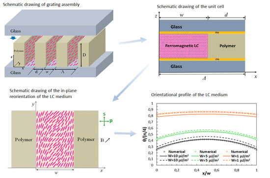
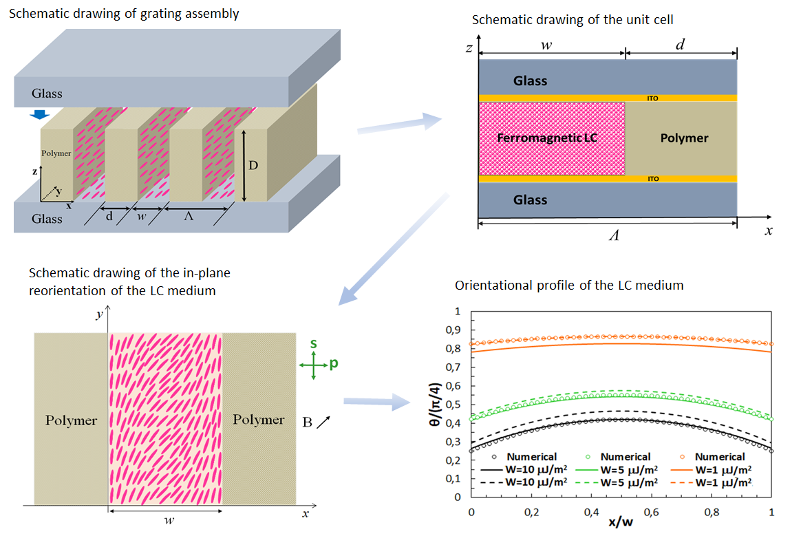
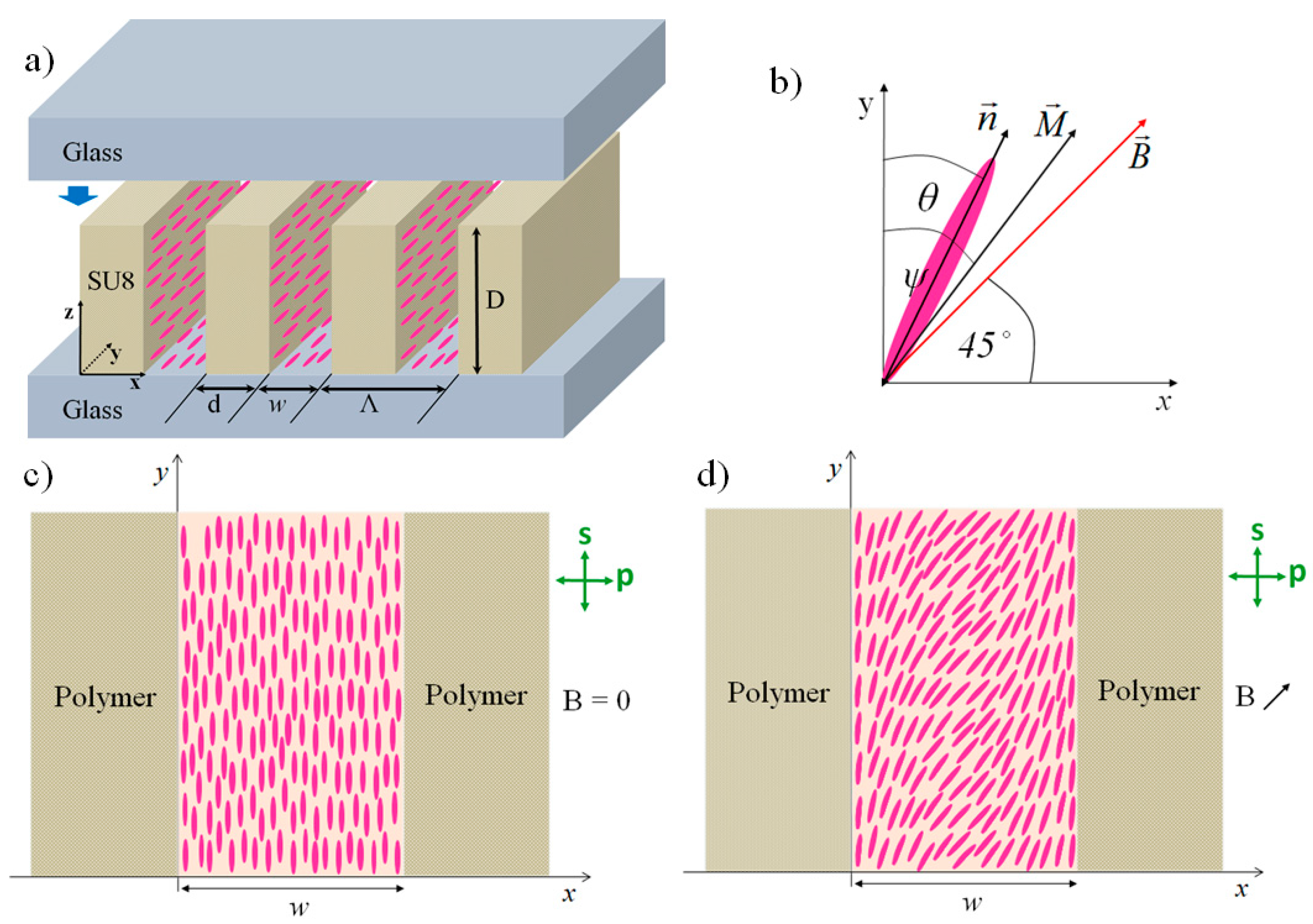
2. Grating Assembly
3. Orientational Profile of the Liquid Crystalline Medium
3.1. Minimization of Free Energy
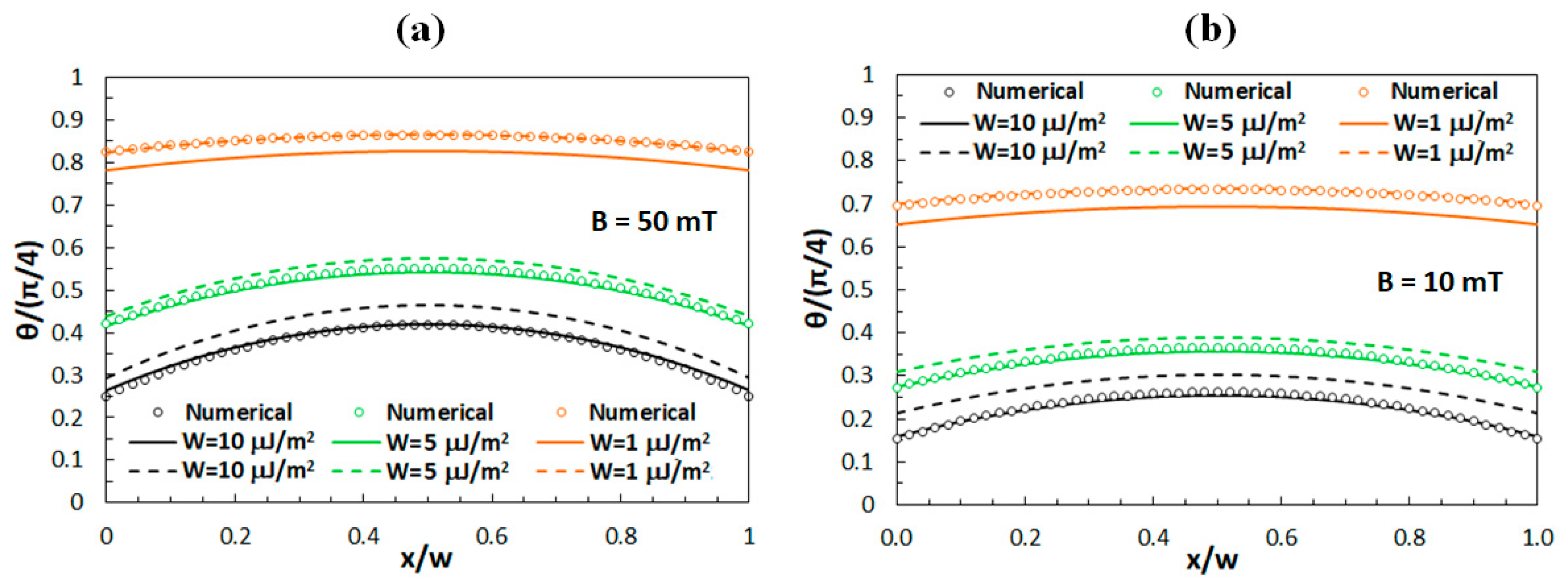
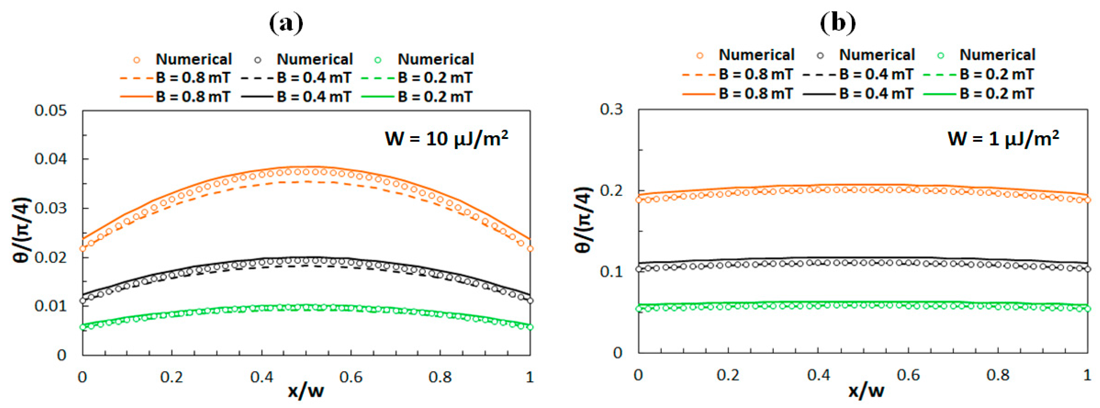
3.2. Comparison of Analytical and Numerical Results
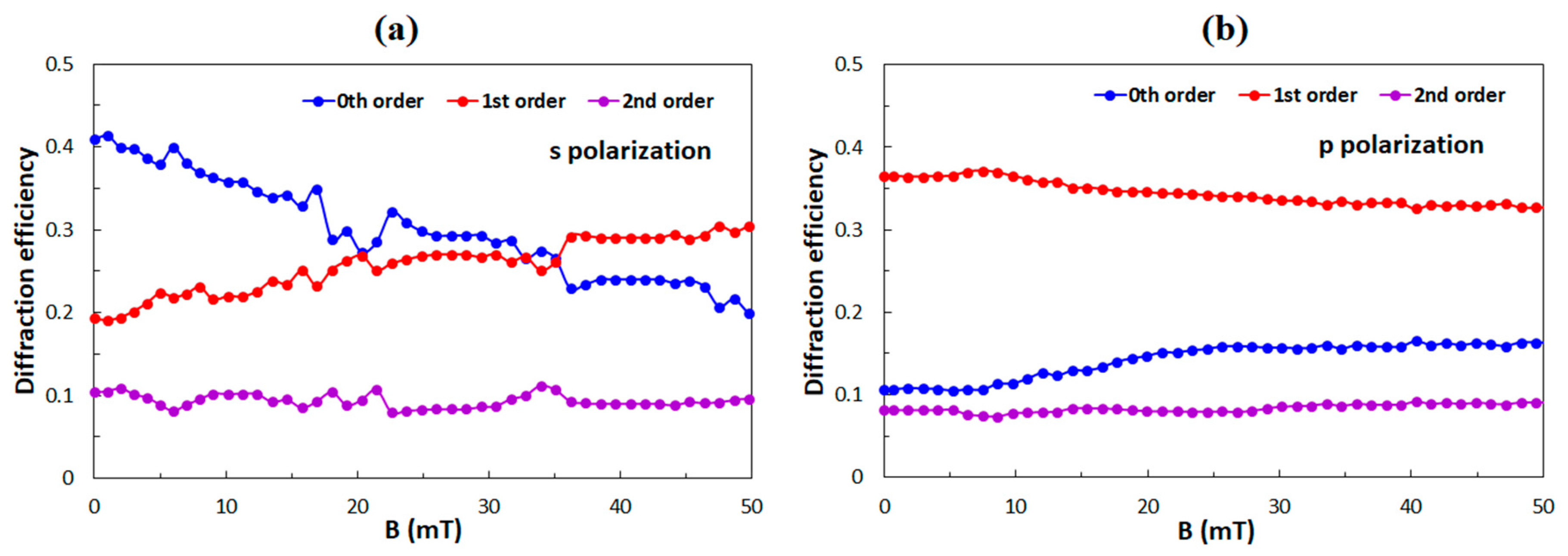
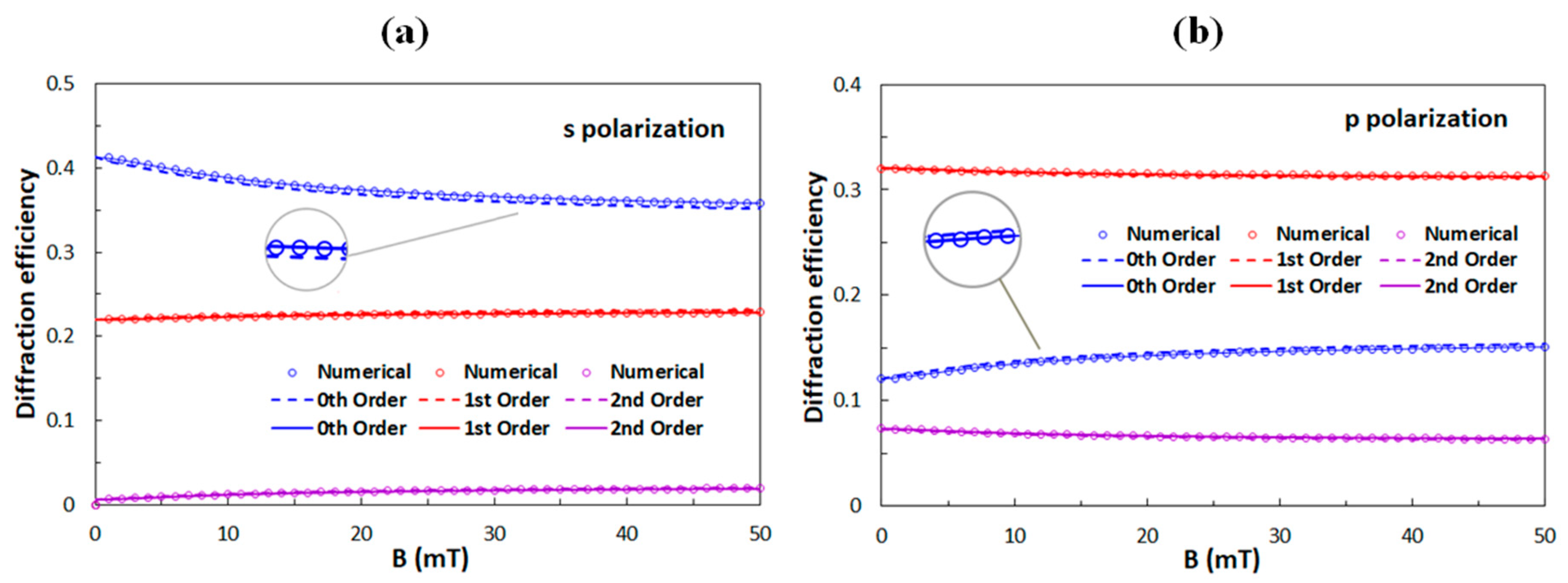
4. Calculation of Optical Diffraction Properties
4.1. Comparison to Previously Investigated Grating Structures
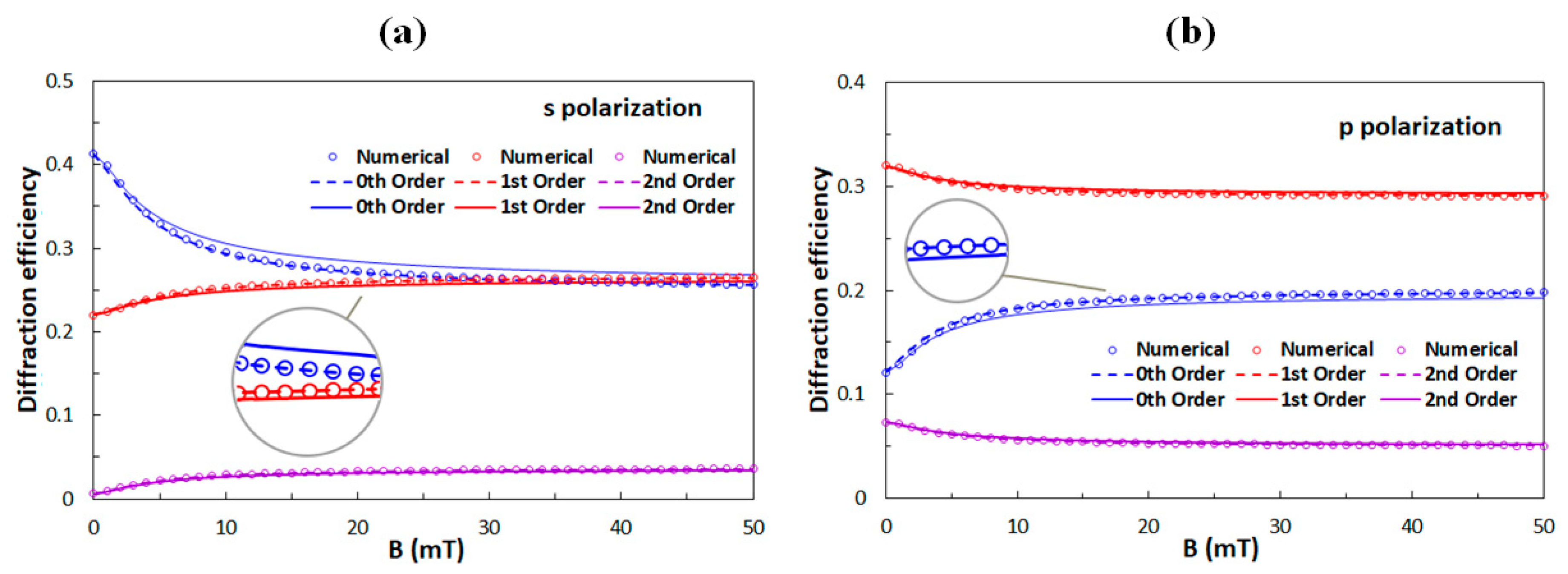
4.2. Design of New Grating Structures
5. Discussion and Conclusions
Author Contributions
Funding
Conflicts of Interest
References
- Fujieda, I. Liquid-crystal phase grating based on in-plane switching. Appl. Opt. 2001, 40, 6252–6259. [Google Scholar] [CrossRef] [PubMed]
- Escuti, M.J.; Oh, C.; Sanchez, C.; Bastiaansen, C.; Broer, D.J. Simplified spectropolarimetry using reactive mesogen polarization gratings. SPIE Opt. Photonics 2006, 6302, 630207. [Google Scholar] [CrossRef]
- Soifer, V.A. Diffractive Optics and Nanophotonics; CRC Press: Boca Raton, FL, USA, 2017. [Google Scholar]
- Apter, B.; Efron, U.; Bahat-Treidel, E. On the fringing-field effect in liquid-crystal beam-steering devices. Appl. Opt. 2004, 43, 11–19. [Google Scholar] [CrossRef]
- Resler, D.P.; Hobbs, D.S.; Sharp, R.C.; Friedman, L.J.; Dorschner, T.A. High-efficiency liquid-crystal optical phased-array beam steering. Opt. Lett. 1996, 21, 689–691. [Google Scholar] [CrossRef]
- Soskind, Y.G. Field Guide to Diffractive Optics. In Field Guide to Diffractive Optics; SPIE Press: Bellingham, WA, USA, 2011. [Google Scholar]
- Park, J.H.; Yu, C.J.; Kim, J.; Chung, S.Y.; Lee, S.D. Concept of a liquid-crystal polarization beam splitter based on binary phase gratings. Appl. Phys. Lett. 2003, 83, 1918–1920. [Google Scholar] [CrossRef]
- Komanduri, R.K.; Oh, C.; Escuti, M.J. 34.4L: Late-News Paper: Polarization Independent Projection Systems Using Thin Film Polymer Polarization Gratings and Standard Liquid Crystal Microdisplays. SID Symp. Dig. Tech. Pap. 2009, 40, 487–490. [Google Scholar] [CrossRef]
- Seo, E.; Kee, H.C.; Kim, Y.; Jeong, S.; Choi, H.; Lee, S.; Kim, J.; Komanduri, R.K.; Escuti, M.J. 39.2: Polarization Conversion System using a Polymer Polarization Grating. SID Symp. Dig. Tech. Pap. 2011, 42, 540–543. [Google Scholar] [CrossRef]
- Chen, J.; Bos, P.J.; Vithana, H.; Johnson, D.L. An electro-optically controlled liquid crystal diffraction grating. Appl. Phys. Lett. 1995, 67, 2588–2590. [Google Scholar] [CrossRef]
- James, S.W.; Tatam, R.P. Optical fibre long-period grating sensors: Characteristics and application. Meas. Sci. Technol. 2003, 14, R49–R61. [Google Scholar] [CrossRef]
- Fattal, D.; Peng, Z.; Tran, T.; Vo, S.; Fiorentino, M.; Brug, J.; Beausoleil, R.G. A multi-directional backlight for a wide-angle, glasses-free three-dimensional display. Nature 2013, 495, 348–351. [Google Scholar] [CrossRef]
- Tien, C.L.; Lin, R.J.; Kang, C.C.; Huang, B.Y.; Kuo, C.T.; Huang, S.Y. Electrically Controlled Diffraction Grating in Azo Dye-Doped Liquid Crystals. Polymers 2019, 11, 1051. [Google Scholar] [CrossRef] [PubMed]
- Chen, C.Y.; Tsai, T.R.; Pan, C.L.; Pan, R.P. Room temperature terahertz phase shifter based on magnetically controlled birefringence in liquid crystals. Appl. Phys. Lett. 2003, 83, 4497–4499. [Google Scholar] [CrossRef]
- Chen, C.Y.; Hsieh, C.F.; Lin, Y.F.; Pan, R.P.; Pan, C.L. Magnetically tunable room-temperature 2π liquid crystal terahertz phase shifter. Opt. Express 2004, 12, 2625–2630. [Google Scholar] [CrossRef]
- Zhang, L.; Fan, Y.; Liu, H.; Han, X.; Lu, W.; Tao, Z.Y. A magnetically tunable non-Bragg defect mode in a corrugated waveguide filled with liquid crystals. Phys. Lett. A 2018, 382, 1000–1005. [Google Scholar] [CrossRef]
- Cao, Y.; Wang, P.X.; D’Acierno, F.; Hamad, W.Y.; Michal, C.A.; MacLachlan, M.J. Tunable Diffraction Gratings from Biosourced Lyotropic Liquid Crystals. Adv. Mater. 2020, 32, e1907376. [Google Scholar] [CrossRef] [PubMed]
- Warner, M.; Terentjev, E.M. Liquid Crystal Elastomers; Oxford University Press: New York, NY, USA, 2007. [Google Scholar]
- Gregorc, M.; Li, H.; Domenici, V.; Drevenšek-Olenik, I. Tunable photonic structures from liquid crystal elastomers. Proc. SPIE 2012, 8556, 855616. [Google Scholar]
- Yu, Y.; Nakano, M.; Ikeda, T. Photomechanics: Directed bending of a polymer film by light. Nature 2003, 425, 145. [Google Scholar] [CrossRef] [PubMed]
- Reshetnyak, V.; Zadorozhnii, V.I.; Pinkevych, I.P.; Bunning, T.J.; Evans, D.R. Surface plasmon absorption in MoS2 and graphene-MoS2 micro-gratings and the impact of a liquid crystal substrate. AIP Adv. 2018, 8, 045024. [Google Scholar] [CrossRef]
- Xu, D.; Tan, G.; Wu, S.T. Large-angle and high-efficiency tunable phase grating using fringe field switching liquid crystal. Opt. Express 2015, 23, 12274–12285. [Google Scholar] [CrossRef]
- Feng, Z.; Ishikawa, K. High-performance switchable grating based on pre-transitional effect of antiferroelectric liquid crystals. Opt. Express 2018, 26, 31976–31982. [Google Scholar] [CrossRef]
- Yeh, P. Optics of Liquid Crystal Displays; Wiley: Hoboken, NY, USA, 1999. [Google Scholar]
- Drevensek-Olenik, I.; Čopič, M.; Sousa, M.E.; Crawford, G.P. Optical retardation of in-plane switched polymer dispersed liquid crystals. J. Appl. Phys. 2006, 100, 033515. [Google Scholar] [CrossRef]
- Morris, S.M.; Gardiner, D.J.; Castles, F.; Hands, P.J.W.; Wilkinson, T.D.; Coles, H.J. Fast-switching phase gratings using in-plane addressed short-pitch polymer stabilized chiral nematic liquid crystals. Appl. Phys. Lett. 2011, 99, 253502. [Google Scholar] [CrossRef]
- Bowley, C.C.; Crawford, G.P. Diffusion kinetics of formation of holographic polymer-dispersed liquid crystal display materials. Appl. Phys. Lett. 2000, 76, 2235–2237. [Google Scholar] [CrossRef]
- Jazbinsek, M.; Drevensek-Olenik, I.; Zgonik, M.; Fontecchio, A.K.; Crawford, G.P. Characterization of holographic polymer dispersed liquid crystal transmission gratings. J. Appl. Phys. 2001, 90, 3831–3837. [Google Scholar] [CrossRef]
- Caputo, R.; de Sio, L.; Veltri, A.; Umeton, C.; Sukhov, A.V. Development of a new kind of switchable holographic grating made of liquid-crystal films separated by slices of polymeric material. Opt. Lett. 2004, 29, 1261–1263. [Google Scholar] [CrossRef]
- Castriota, M.; Fasanella, A.; Cazzanelli, E.; de Sio, L.; Caputo, R.; Umeton, C. In situ polarized micro-Raman investigation of periodic structures realized in liquid-crystalline composite materials. Opt. Express 2011, 19, 10494–10500. [Google Scholar] [CrossRef]
- Mertelj, A.; Lisjak, D.; Drofenik, M.; Čopič, M. Ferromagnetism in suspensions of magnetic platelets in liquid crystal. Nature 2013, 504, 237–241. [Google Scholar] [CrossRef]
- Mertelj, A.; Lisjak, D. Ferromagnetic nematic liquid crystals. Liq. Cryst. Rev. 2017, 5, 1–33. [Google Scholar] [CrossRef]
- Naruta, T.; Akita, T.; Uchida, Y.; Lisjak, D.; Mertelj, A.; Nishiyama, N. Magnetically controllable random laser in ferromagnetic nematic liquid crystals. Opt. Express 2019, 27, 24426–24433. [Google Scholar] [CrossRef]
- Sebastián, N.; Osterman, N.; Lisjak, D.; Čopič, M.; Mertelj, A. Director reorientation dynamics of ferromagnetic nematic liquid crystals. Soft Matter 2018, 14, 7180–7189. [Google Scholar] [CrossRef]
- Korostil, A.M.; Krupa, M.M. Magneto-nematic coupled dynamics in ferromagnetic nematic liquid crystals under magnetic field. Mol. Cryst. Liq. Cryst. 2020, 699, 82–89. [Google Scholar] [CrossRef]
- Moharam, M.G.; Gaylord, T.K. Rigorous coupled-wave analysis of planar-grating diffraction. J. Opt. Soc. Am. 1981, 71, 811–818. [Google Scholar] [CrossRef]
- Moharam, M.G.; Gaylord, T.K. Rigorous Coupled-Wave analysis of grating diffraction—E-Mode polarization and lossless. J. Opt. Soc. Am. 1983, 73, 451–455. [Google Scholar] [CrossRef]
- Kogelnik, H. Coupled Wave Theory for Thick Hologram Gratings. Bell Syst. Tech. J. 1969, 48, 2909–2947. [Google Scholar] [CrossRef]
- Moharam, M.G.; Gaylord, T.K.; Grann, E.B.; Pommet, D.A. Formulation for stable and efficient implementation of the rigorous coupled-wave analysis of binary gratings. J. Opt. Soc. Am. A 1995, 12, 1068–1076. [Google Scholar] [CrossRef]
- Gao, S.; Fleisch, M.; Rupp, R.A.; Cmok, L.; Medle-Rupnik, P.; Mertelj, A.; Lisjak, D.; Zhang, X.; Drevensek-Olenik, I. Magnetically tunable optical diffraction gratings based on a ferromagnetic liquid crystal. Opt. Express 2019, 27, 8900–8911. [Google Scholar] [CrossRef]
- Fleisch, M.; Gao, S.; Bošnjaković, D.; Zhang, X.; Rupp, R.; Drevenšek-Olenik, I. Laser-written polymeric scaffolds for micro-patterned liquid crystal alignment. Liq. Cryst. 2019, 46, 2075–2084. [Google Scholar] [CrossRef]
- Ji, Z.; Zhang, X.; Shi, B.; Li, W.; Luo, W.; Drevensek-Olenik, I.; Wu, Q.; Xu, J. Compartmentalized liquid crystal alignment induced by sparse polymer ribbons with surface relief gratings. Opt. Lett. 2016, 41, 336–339. [Google Scholar] [CrossRef]
- Zhang, X.; Xu, J.; Li, W.; Drevensek-olenik, I.; Cui, W.; Shi, B.; Wang, Z.; Wu, Q.; Kong, Y. Micro/nano region liquid crystal alignment method and system thereof based on laser direct writing. Nankai University. CN Patent 148,861,651, 5 September 2018. [Google Scholar]
- Lee, C.H.; Yoshida, H.; Miura, Y.; Fujii, A.; Ozaki, M. Local liquid crystal alignment on patterned micrograting structures photofabricated by two photon excitation direct laser writing. Appl. Phys. Lett. 2008, 93, 173509. [Google Scholar] [CrossRef]
- Zhou, X.; Hou, Y.; Lin, J. A review on the processing accuracy of two-photon polymerization. AIP Adv. 2015, 5, 030701. [Google Scholar] [CrossRef]
- Berreman, D.W. Alignment of Liquid Crystals by Grooved Surfaces. Mol. Cryst. Liq. Cryst. 1973, 23, 215–231. [Google Scholar] [CrossRef]
- Li, W.; Cui, W.; Zhang, W.; Kastelic, A.; Drevensek-Olenik, I.; Zhang, X. Characterisation of POLICRYPS structures assembled through a two-step process. Liq. Cryst. 2014, 41, 1315–1322. [Google Scholar] [CrossRef]
- De Gennes, P.G.; Prost, J. The Physics of Liquid Crystals, 2nd ed.; Oxford University Press: Oxford, UK; New York, NY, USA, 1993. [Google Scholar]
- Chandrasekhar, S. Liquid Crystals; Cambridge University Press: Cambridge, UK, 1977. [Google Scholar]
- Chao, P.C.P.; Kao, Y.Y.; Hsu, C.J. A new negative liquid crystal lens with multiple ring electrodes in unequal widths. IEEE Photonics J. 2012, 4, 250–266. [Google Scholar] [CrossRef]
- Potisk, T.; Mertelj, A.; Sebastián, N.; Osterman, N.; Lisjak, D.; Brand, H.R.; Pleiner, H.; Svenšek, D. Magneto-optic dynamics in a ferromagnetic nematic liquid crystal. Phys. Rev. E 2018, 97, 012701. [Google Scholar] [CrossRef] [PubMed]
- Stewart, I.W. The Static and Dynamic Continuum Theory of Liquid Crystals: A Mathematical Introduction; CRC Press: Boca Raton, FL, USA, 2004. [Google Scholar]
- MicroChem. SU-8 3000 Data Sheet. Available online: http://microchem.com/pdf/SU8%203000%20Data%20Sheet.pdf (accessed on 12 May 2020).
- Li, J.; Wen, C.H.; Gauza, S.; Lu, R.; Wu, S.T. Refractive Indices of Liquid Crystals for Display Applications. J. Disp. Technol. 2005, 1, 51–61. [Google Scholar] [CrossRef]
- Gaylord, T.K.; Moharam, M.G. Thin and thick gratings: Terminology clarification. Appl. Opt. 1981, 20, 3271. [Google Scholar] [CrossRef]
- Introduction to S4—S4 1.1 Documentation. Available online: https://web.stanford.edu/group/fan/S4/ (accessed on 23 May 2020).
- Potisk, T.; Pleiner, H.; Svenšek, D.; Brand, H.R. Effects of flow on the dynamics of a ferromagnetic nematic liquid crystal. Phys. Rev. E 2018, 97, 042705. [Google Scholar] [CrossRef]
- Zadorozhnii, V.I.; Pinkevich, I.P.; Reshetnyak, V.; Burylov, S.V.; Sluckin, T.J. Adsorption Phenomena and Macroscopic Properties of Ferronematics Caused by Orientational Interactions. Mol. Cryst. Liq. Cryst. 2004, 409, 285–292. [Google Scholar] [CrossRef]
- Buluy, O.; Ouskova, E.; Reznikov, Y.; Glushchenko, A.; West, J.; Reshetnyak, V. Magnetically induced alignment of FNS. J. Magn. Magn. Mater. 2002, 252, 159–161. [Google Scholar] [CrossRef]
- Nie, X.; Lu, R.; Xianyu, H.; Wu, T.X.; Wu, S.T. Anchoring energy and cell gap effects on liquid crystal response time. J. Appl. Phys. 2007, 101, 103110. [Google Scholar] [CrossRef]
- Solodar, A.; Cerkauskaite, A.; Drevinskas, R.; Kazansky, P.G.; Abdulhalim, I. Ultrafast laser induced nanostructured ITO for liquid crystal alignment and higher transparency electrodes. Appl. Phys. Lett. 2018, 113, 081603. [Google Scholar] [CrossRef]
- Choi, G.J.; Ryu, D.G.; Gwag, J.S.; Choi, Y.; Kim, T.H.; Park, M.S.; Park, I.; Lee, J.W.; Park, J.G. Anchoring strength of indium tin oxide electrode used as liquid crystal alignment layer. J. Appl. Phys. 2019, 125, 064501. [Google Scholar] [CrossRef]
Publisher’s Note: MDPI stays neutral with regard to jurisdictional claims in published maps and institutional affiliations. |


© 2020 by the authors. Licensee MDPI, Basel, Switzerland. This article is an open access article distributed under the terms and conditions of the Creative Commons Attribution (CC BY) license (http://creativecommons.org/licenses/by/4.0/).
Share and Cite
Bošnjaković, D.; Sebastián, N.; Drevenšek-Olenik, I. Magnetically Tunable Liquid Crystal-Based Optical Diffraction Gratings. Polymers 2020, 12, 2355. https://doi.org/10.3390/polym12102355
Bošnjaković D, Sebastián N, Drevenšek-Olenik I. Magnetically Tunable Liquid Crystal-Based Optical Diffraction Gratings. Polymers. 2020; 12(10):2355. https://doi.org/10.3390/polym12102355
Chicago/Turabian StyleBošnjaković, Dejan, Nerea Sebastián, and Irena Drevenšek-Olenik. 2020. "Magnetically Tunable Liquid Crystal-Based Optical Diffraction Gratings" Polymers 12, no. 10: 2355. https://doi.org/10.3390/polym12102355
APA StyleBošnjaković, D., Sebastián, N., & Drevenšek-Olenik, I. (2020). Magnetically Tunable Liquid Crystal-Based Optical Diffraction Gratings. Polymers, 12(10), 2355. https://doi.org/10.3390/polym12102355