Article

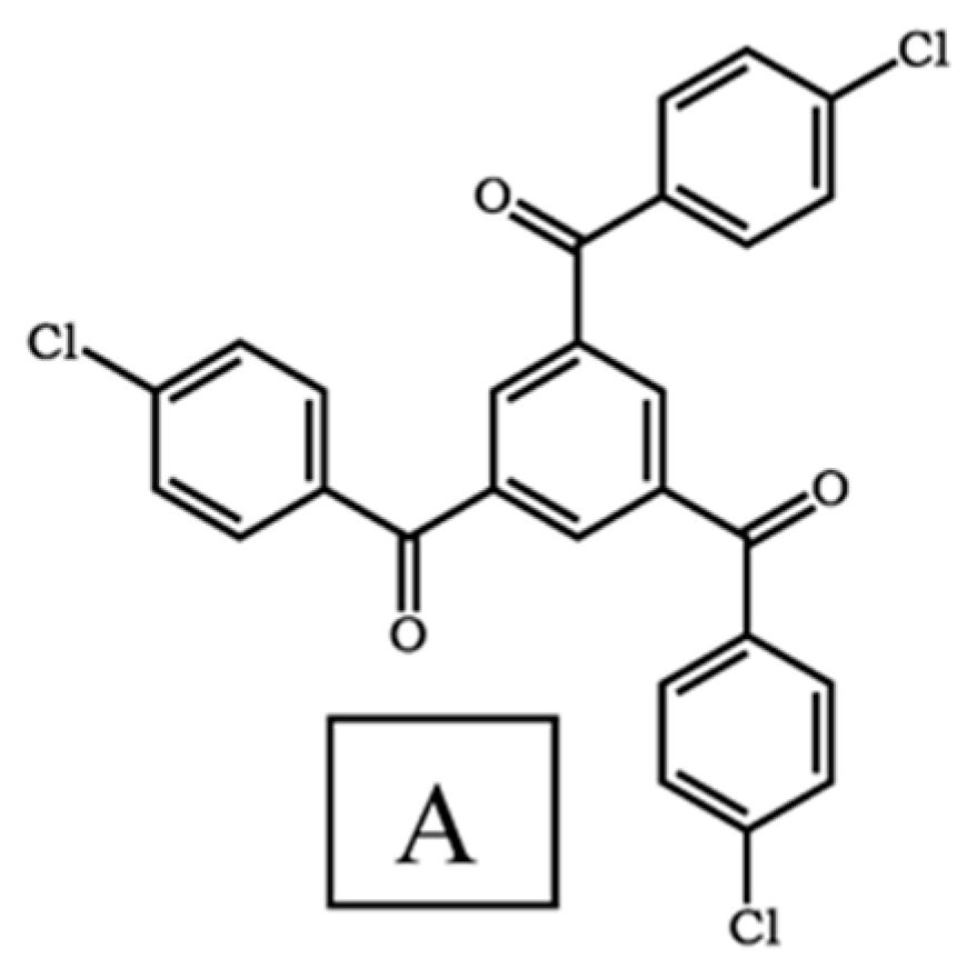
Synthesis, Crystal Structure, Hirshfeld Surface Analysis, Energy Framework Calculations, and Halogen Bonding Investigation of Benzene-1,3,5-triyltris((4-chlorophenyl)methanone)

by
Hawazen M. Hassanain
*,
Samah Al-Sharif
,
Huda A. Al-Ghamdi
,
Layla M. Nahari
,
Ahlam I. Al-Sulami
,
Sameera M. Mousally
and
Khadijah M. Al-Zaydi
*
Department of Chemistry, College of Science, University of Jeddah, P.O. Box 80327, Jeddah 21589, Saudi Arabia
*
Authors to whom correspondence should be addressed.
Crystals 2024, 14(1), 17; https://doi.org/10.3390/cryst14010017
Submission received: 20 November 2023 / Revised: 19 December 2023 / Accepted: 20 December 2023 / Published: 24 December 2023

Abstract

:
We synthesized 1,3,5-triyltris((4-chlorophenyl)methanone) by a condensation reaction in glacial acetic acid and studied utilizing spectroscopic and analytical techniques such as ultraviolet, infrared, mass, elemental, and nuclear magnetic resonance (NMR) spectroscopy, as well as X-ray crystallography. The effect of chlorine substitution in the 1,3,5-triaroylbenzene compound in solid-state arrangements was studied. Halogen bonds are detected in the solid-state structures of the titled compound. A dimeric structure is formed due to the presence of two C-Cl···Cl Type I halogen interactions. Additionally, a delocalized Type III C-Cl···π interaction were reported. C-Cl···H hydrogen bonding and π···π interaction were also reported. Hirshfeld surface analysis, 3D fingerprint, the energy framework, and the electro-optic potential were used to evaluate such interactions.

1. Introduction

Crystal engineering’s fundamental purpose is to use intermolecular interactions to assemble crystalline materials with desired physiochemical qualities [1,2]. Intermolecular interactions that have been successfully used to prepare self-assembled structures include hydrogen bonding (HB) [3,4,5,6,7], halogen bonding (XB) [8,9,10,11,12], chalcogen bonding, π–π stacking [2,13], hydrophobic interactions, electrostatic interactions [14], and van der Waals interactions [15,16,17]. The hydrogen bond is, without a doubt, the most influential and well-understood intermolecular force [18], with a wide range of applications, including pharmaceuticals, co-crystallizations [19], and the invention of new energy materials [20]. In the last few years, the observation and understanding of potentially conflicting intermolecular interactions, such as halogen and chalcogen bonding, has opened up possibilities for the bottom-up design of novel crystalline materials [21,22]. It is interesting to note that pnictogen and chalcogen bonds are structurally similar to XB. However, this comparison is less informative because the properties of these bonds are not as well-understood. Indeed, the majority of research on these bonds is crystallographic or computational in nature [23,24].
The terms “iodine bond” [25,26,27], “bromine bond” [25,27], “chlorine bond” [27,28,29], and “fluorine bond” [27,30,31,32], which refer to specific interactions involving one of the four halogen atoms as an electrophilic site [27], have occasionally appeared in the literature. All those terms could be categorized under the broader category of interactions known as halogen bonds (XB) [27]. Halogen bonding (XB) is an attractive and valuable noncovalent interaction, which has recently been exploited as a powerful tool in the field of crystal engineering [2,11,23,33], leading to the design of functional materials. Those materials bonding find applications in the areas of reactivity [34], catalysis [35], self-assembly [23,36,37], and medicine, and expanding to materials chemistry [23,38]. Terminal halides have been implicated in the self-assembly of organic molecules and dye compound, via a range of intermolecular interactions, involving H-bonds, halogen–halogen, and halogen–arene contacts [39,40].
It should be noted that the IUPAC Task Group provided a unified definition of XB in 2009 for the first time: Halogen bonding (XB) occurs when there is evidence of a net attractive interaction between an electrophilic region associated with a halogen atom in a molecular entity and a nucleophilic region in another, or the same, molecular entity [41,42,43]. Halogen bonding with halogen atoms like Br and I is a newly recognized type of strong and directed contact established by IUPAC in 2013, which is analogous to hydrogen bonding [37]. Fluorine is not usually considered a halogen bond donor [27,44,45,46,47]. This is explained to be as a result of the lack of a discernible σ-hole when a fluorine atom is covalently bonded. However, if the fluorine atom is attached to a particularly strong electron-withdrawing group, it could act as an XB donor [27,44,46,47,48].
Over the years, halogen bonds have been well-developed in the field of crystal engineering [2,11,33,49], leading to the design of functional materials [34,50], and the construction of porous materials based on halogen bonding. This could lead to the formation of flexible, dynamic voids [51,52,53,54], opening up an opportunity to develop new and adaptable materials [54,55].
Numerous analytical techniques have been used to determine the presence of XB interactions including single-crystal, powder X-ray diffraction, Fourier-transform infrared (FTIR) spectroscopy, Raman spectroscopy, NMR spectroscopy, and Uv-Vis spectroscopy [56]. FTIR and Raman spectroscopy are valuable for studying the XB interaction in the far-IR region [56]. However, NMR spectroscopy is an essential technique to evaluate the occurrence of an XB interaction and to study its behavior in solution. NMR parameters (i.e., chemical shifts and coupling constants) could give evidence for the occurrence, thermodynamics, and local structure of the XB interaction since it will be possible to calculate association constants in XB complexes through titrations. Additionally, NMR spectroscopy will offer the possibility of running more complex experiments (such as HOESY and NQR experiments) that exploit the large quadrupolar interactions of halogen atoms [56]. However, in some cases, Uv-Vis spectroscopy becomes an alternative for probing the XB interactions in solution and the thermodynamic characteristics of XB complexes, especially in transition metal organic halogen bonding. It should be mentioned that crystal engineering and theoretical computation for studying the XB interaction in solution is very limited, possibly because the XB interaction in solution is relatively weaker and more complicated than that in the gas or solid state.
Single-crystal X-ray structure analysis played a key role because it provides more structural details such as the geometrical features of single molecules and their relative arrangement in the crystal, which allowed the strength and directionality of the XB to be realized [56]. When describing halogen-bonding interactions in solid-state structures, Sakurai et al. [57] observed that (CX1···X2C) connections are present in two geometries. These geometries were classified into Type I and Type II by Desiraju and R. Parthasarath [58,59]. Type I are symmetrical interactions where θ1 ≈ θ2, and Type II are bent interactions where θ1 ≈ 180° and θ2 ≈ 90° [27,58,59,60]. Mostly, the θ2 angle occurs for the lighter halogen atoms, which might be due to the possibility of a positive polarization on the heavier halogen and negative polarization on the lighter halogen [60]. Desiraju suggested the following criteria for the classification of Type I and Type II: contacts with 0° ≤ |θ1–θ2| ≤ 15° are Type I; while contacts with |θ1–θ2| ≥ 30° are Type II; and contacts with 15° ≤ |θ1–θ2| ≤ 30° are quasi-Type I/Type II [34]. For the distances, Type I interactions were more frequent at distances shorter than the van der Waals contacts, while Type II interactions were more frequently closer to the van der Waals limit [60,61]. This behaviour has been explained as a direct effect of the electrostatic nature of the XB. For example, Type II (I···I) contacts formed at longer distances, while Type I contacts, being dispersive forces, operated preferentially at shorter distances. Recently, Type III halogen bonding or di-hole has been introduced and discussed [62]. This concept was expanded to include many halogen-B interactions, where B might be any Lewis base or other electronegative chemical entity. In particular, both liquid and solid halogen–oxygen, halogen–nitrogen, or halogen–π interactions have been recorded. A halogen bond can also be classified in terms of the type of atoms to halogen···halogen, halogen···chalcogen, and halogen···pnictogens, which are ubiquitous, noncovalent interactions in crystal engineering [63]. Typically, the interatomic distances in halogen bonding is mostly closer than the sum of the interacting atoms’ van der Waals radii.
On the other hand, 1,3,5-triaroylbenzene (TAB) compounds are a significant class of compounds with a unique structure finding applications in medicine, nonlinear optical materials [64], supermolecular assemblies [64,65,66,67], and functional polymer materials [64]. Additionally, TAB compounds have been reported to display a variety of solid-state characteristics relevant to current investigations in crystal engineering [64,66].
Various types of hydrogen bonding (HB) were reported to play significant roles in defining the solid-state structures of TAB compounds [66,68]. Additionally, halogen bonding appears to be significant in defining the structures of the chloro, bromo, and iodo derivatives [66]. Both the chloro and bromo derivatives are isostructural and display numerous X···O=C interactions [67], whereas the iodo derivative exhibits Type II I···I halogen bonding [66]. In the current study, we intend to explore the intermolecular interactions that are present in the crystal structure of 1,3,5-triyltris((4-chlorophenyl)methanone).
X-ray crystallography has been utilized to determine whether the distance between a halogen and its neighbor is shorter than the total of the van der Waals radii, and if this is true for two or more atoms near a specific halogen, the halogen is involved in one or more XB [69,70]. Therefore, the method used in this paper is to investigate the experimental distances and angles of XB intermolecular interactions, and other non-covalent interaction seen in compound A (Figure 1).

2. Materials and Methods

General experimental: All chemicals (reagent grade) were purchased from Sigma Aldrich and Fisher Scientific UK and utilized without additional purification. Single-crystal analysis was determined using X-ray diffraction diagrams and calculations were performed using Maxus (Bruker Nonius, Delft & Macscienece, Tokyo, Japan). 1H and 13C NMR spectra were recorded at room temperature in DMSO on a Bruker DPX 440 MHz spectrometer, operating at 400 and 100 MHz, respectively. Infrared spectra (FT-IR) were performed on Pye Unicam SP 3-300 Spectrophotometer. Mass spectra were recorded on a positive ion mode on a Mass Spectra Shimadzu GCMS-QP 1000 Ex mass spectrometer at 70 eV.
Synthesis of benzene-1,3,5-triyltris((4-chlorophenyl)methanone) (A): 30 mL of acetic acid was mixed with (0.1 mol) 1-(4-Chlorophenyl)-3-(dimethylamino)prop-2-en-1-one in presence of (0.4 mol) of pyridinium chloride ([PyH]Cl). The mixture was heated for three hours before being cooled to room temperature. After filtration to separate the product A from the ethanol/dioxane 1:3 mixtures, the product crystallized. Filtration is used to separate the 1,3,5-trisubstituted benzene substituents from dioxane, and then the crystals are recrystallized in ethanol/dioxane 1:3 mixtures.
1H NMR; (DMSO-d6); 7.65 (d,J = 8.8 Hz, Ar-H), 7.86 (d, 6H,J = 8.8 Hz, Ar-H), 8.23 (s, 3H, Ar-H) ppm. IR: νmax/(KBr) 3082(CH aromatic), 1657 (C=O ketone) cm−1 13C NMR; (DMSO-d6); 129.46, 132.34, 135.36, 138.90 (C6H4-Cl-p), 134.31, 137.81 (C6H3-CO), 193.80 (C=O) ppm. MS: m/z, 493 (M+ + 1).
Single-crystal X-ray diffraction studies: Single-crystal diffraction data were collected for A, at 293 K on a Rigaku R-AXIS RAPID diffractometer using Mo Kα radiation (λ = 0.71075).
Crystal data for A: C27 H15 Cl3 O3: space group P 21/c (no. 14), a = 24.160(4) Å, b = 9.2561(15) Å, c = 10.5208(14) Å, alpha = 90 beta = 99.446(7) gamma = 90, V = 2320.8(6), Z = 4, Dcalc = 1.413 g cm−3, μ = 0.422 mm−1, F(000) = 1008. A total of 16,464 reflections were collected, of which 3989 were unique, with Rint = 0.1177. Final R1 (wR2) = 0.1562 (0.3352) with GOF = 1.050.
Hirshfeld surface (HS) and fingerprint: Hirshfeld surface (HS) represents an important advancement that allows supramolecular chemists and crystal engineers to gain a deep understanding of crystal-packing behaviour by determining and evaluating intramolecular interactions between molecules in crystal packing [71]. This approach is unique in its ability to calculate these interactions and give a unique visualization for each crystal structure. The crystallographic information file (CIF) of the molecule under examination is entered into the Crystal Explorer 17.5 software [71,72,73,74]. The production of 3D molecular surface contours and 2D fingerprint plots is one of HS’s key characteristics. These plots and contours combine to generate a van der Waals (vdW) surface surrounding the molecule, showing the molecule’s space within the crystal structure. A Hirshfeld surface is made up of tens of thousands of surface points and is determined by two parameters: (i) de, indicating the distances between the surface and the nearest atoms outside the surface, and (ii) di, denoting the distances between the surface and the nearest atoms within the surface [73]. The only limitation of using di and de method is that it is difficult to highlight close interactions between large atoms because it does not take atom sizes into account. As a result, both di and de distances can then be normalized (dnorm), and Equation (1) is used [75].
d n o r m = d i r i v d w   r i v d w + d e r e v d w r e v d w
These values can be represented as a three-dimensional surface, and features and patterns for structural analysis can be detected using a red–green–blue color scheme [73,75]. Hirshfeld surface plots for the title compounds were created using a standard surface solution of three-dimensional dnorm surfaces plotted across a set colour scale of 0.0870 (red) to 1.2944 (blue) a.u using the Crystal Explorer 17.5 [71,72,73,74]. Crystal Explorer 17.5. [71,72,73,74] was used to visualize interactions in molecular crystals using Hirshfeld surface tools and to analyze 2D fingerprint plots (FPs).
3D deformation density: Crystal Explorer 17.5 [71,72,73,74] was used to plot 3D deformation density for the molecule at the crystal geometry over electron density iso-surface (the result is 0.008 e/au3). This function calculated uses the B3LYP/6-31G(d,p) level of theory.
Electrostatic potential (ESP), promolecular surface, electron density: The molecular structure and the 3D models of A were generated using Molview [76] web-service (http://www.molview.org, accessed on 4 December 2023) in order to generate a molecular electrostatic potential (MEP) surface of A. Additionally, electrostatic potential (ESP) mapped onto Hirshfeld surfaces (40, 47) were obtained at the wave function of HF/STO-3G level (47) by using Crystal Explorer 17.5 [71,72,73,74]. Crystal Explorer 17.5 (52–54, 56) was used to plot 3D promolecular surface map over di, de, and dnorm. Crystal Explorer 17.5 (52–54, 56) was used to plot electron density surface map over di, de, and dnorm, using wave function HF/STO-3G.
Energy framework calculations: Crystal Explorer 17.5 [71,72,73,74] was used to compute the pairwise interaction energy between the molecules within the crystal using the wave function calculated at the B3LYP/6-31G(d,p) level of theory. The four energy components, electrostatic (E ele), polarization (E pol), dispersion (E dis) and exchange–repulsion (E rep), were obtained using the wave function calculated at the B3LYP/6-31G(d,p) level of theory. They involve electrostatic energy, which is concerned with the forces among charged particles; polarization energy, which is concerned with the interactions that result from the distortion of a molecule’s electron cloud by other near-charge distributions; dispersive energy, which is concerned with the weak attractive forces triggered by temporary fluctuations in a molecule’s electron distribution; and repulsive energy, which is the energy required to overcome the forces that prevent a pair of molecules from interacting. Combining these various kinds of interaction energies together yields the total interaction energy of the molecule under consideration, as shown in the following formula:
Etot = Eele + Epol + Edis + Erep
Scale factors (indicated by Ks in the equation) are used to account for potential differences in the molecule energies determined from the generated wave function using density functional theory:
Etot = KeleE′ele + KpolE′pol + KdisE′dis + KrepE′rep
Both variational and perturbation-based approaches have been widely used in energy-decomposition processes to apply the interaction energy breakdown method used in this study [77]. This approach provides the derivation of the classical electrostatic energy of interaction between monomer charge distributions, E′ele, and the exchange–repulsion energy, E′rep, from the antisymmetric product of the monomer spin orbitals. The polarization energy, E′pol, was determined by adding together atoms using terms such as 1 2 α |F|2, in which isotropic atomic polarizabilities were represented by the electric field F, which was computed at each atomic nucleus based on the charge distribution of the other monomer. By adding Grimme’s D2, the dispersion energy term, E′dis, was found [78]. Calibration against conclusions from quantum mechanics is used to calculate the scale factors, such as Kele, as stated in Equation (2) [77,79,80]. The computed interaction energies were then used to develop three-dimensional energy frameworks. These frameworks are beneficial in observing how the tested compounds are organized within their particular crystal structures [77,81,82].

3. Results and Discussion

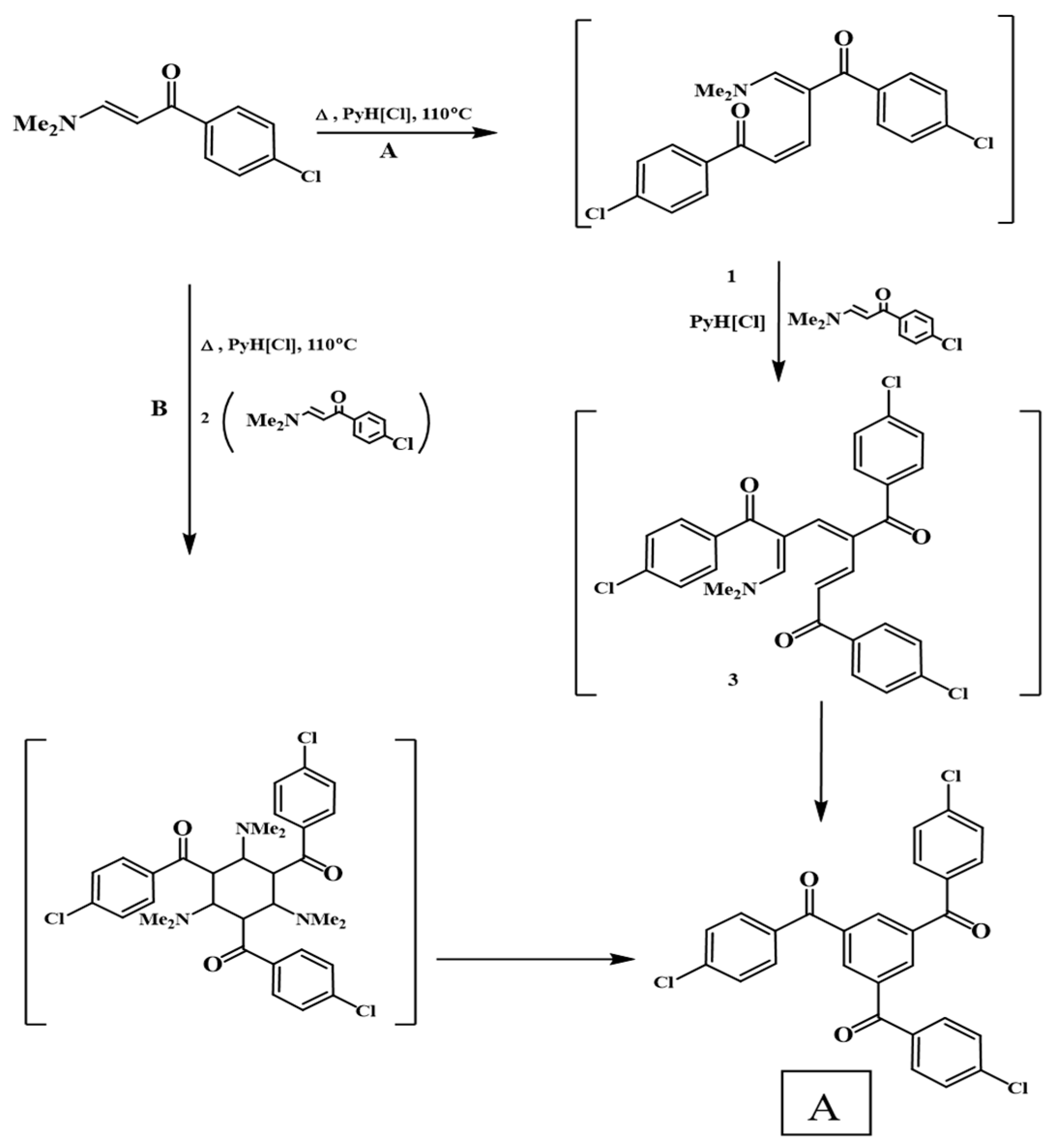
3.1. Synthesis and Characterization

The synthetic procedures used to make A are summarized in Scheme 1. 1, 2. Briefly, 1-(4-Chlorophenyl)-3-(dimethylamino)prop-2-en-1-one is heated with glacial acetic acid for four hours, and compound A is formed. The reaction can take place by condensation of the two enaminones, forming an open dimer 1 as an intermediate compound; the latter is condensed with another molecule of enaminone to form the trimer (5,3,1-trimer clearly replaced benzene) A as a final product of the reaction via the intermediate compound 2 as it is through path A (Scheme 1). The trimer may be formed in one step; three molecules of enaminone are condensed simultaneously through the intermediate compound 3, as is the clear B path [83]. The expected signals in mass spectrometry (MS), IR, 1H-, and 13C NMR spectra of A were obtained (Figures S1–S4 of the Supplementary Materials).

3.2. X-ray Structure and Hirshfeld Surface Analysis

The X-ray structure of compound A crystallizes in a monoclinic system under the space group P 21/c, with cell parameters a = 24.160 (4) A°, b = 9.2561 (15) A°, c = 10.5208 (14) A°, α = 90°, β = 99.446 (7)°, and γ = 90°. In order to understand the crystal packing of compound A, and the role and nature of halogen bonding, Hirshfield surface analysis (HS) was used. HS represents an important advancement that allows supramolecular chemists and crystal engineers to gain a deep understanding of crystal-packing behaviour by determining and evaluating intramolecular interactions between molecules in crystal packing [71]. Hirshfeld surface plots for the title compounds were created using a standard surface solution of three-dimensional dnorm surfaces plotted across a set colour scale of 0.0870 (red) to 1.2944 (blue) a.u using the Crystal Explorer 17.5 [71,72,73,74]. Additionally, di, de, shape index surfaces, and curvedness surfaces were generated for compound A as shown in Figure 2 and Figure 3, and Figures S5 and S6 of the Supplementary Materials. Those surfaces were generated in order to understand the crystal packing of compound A, and the role and the nature of halogen bonding.
The title molecule’s shape-index surfaces were constructed in the ranges −1 to 1 Å as shown in Figure 2a. Typically, the convex blue areas represent hydrogen or halogen donor groups, while the concave red areas represent hydrogen or halogen acceptor groups. On the shape-index map, π···π interactions are represented by adjacent red and blue triangles. There is evidence of the existence of π···π interactions between nearby molecules in the title complex, as shown in Figure 2a–c. Moreover, the title molecule’s A curvedness surfaces were constructed in the ranges −4 to 0.4 Å as shown in Figure 2b. Usually, the flat surface area appeared in green regions, while the curvature area appeared as blue regions. Flat regions around the rings could be evidence of a π–π stacking interaction.

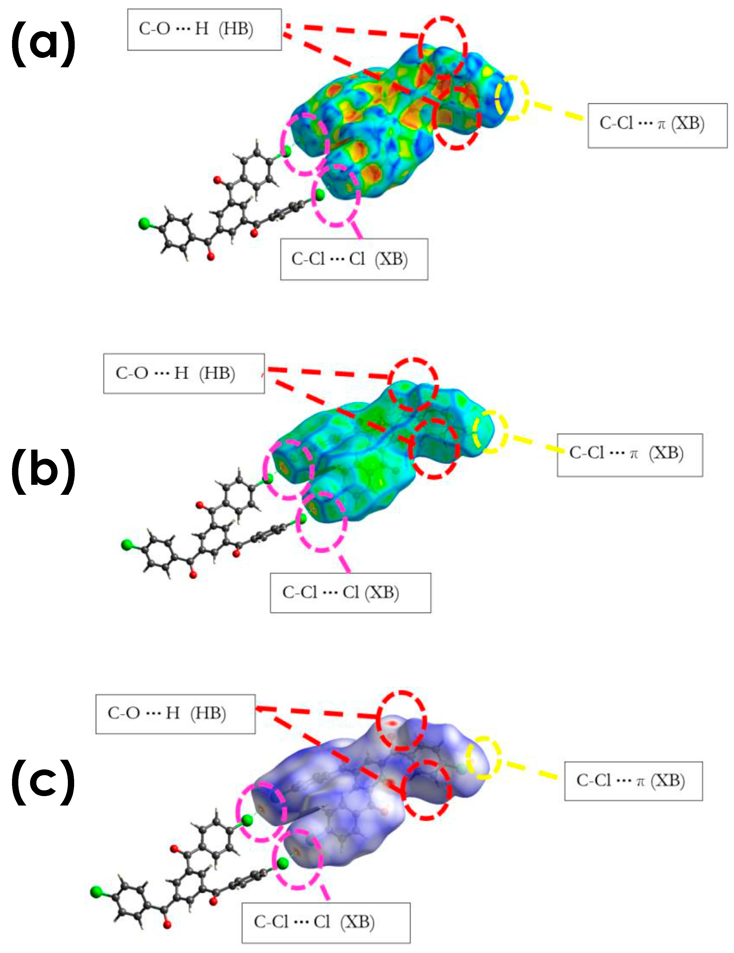
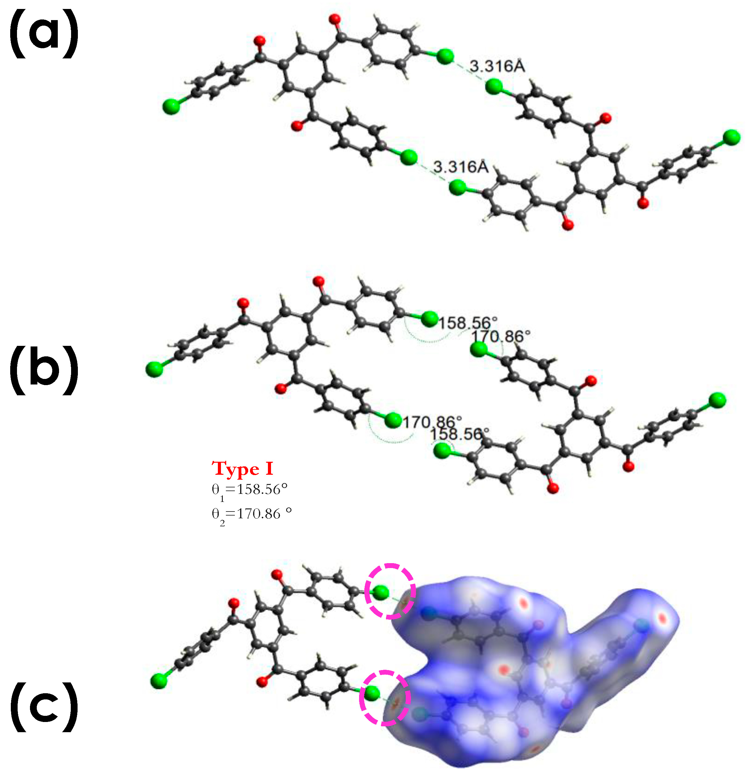
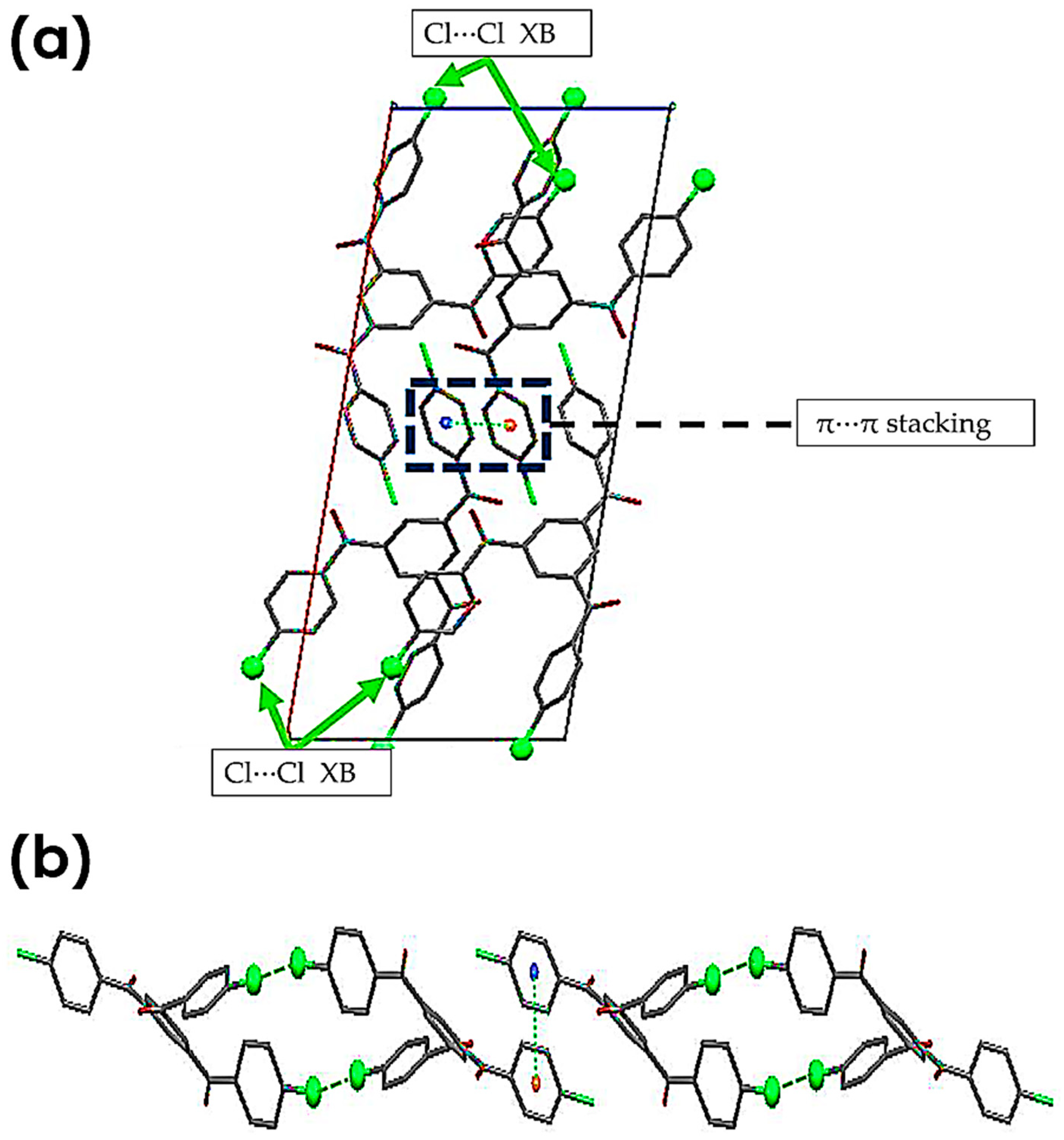
3.2.1. C-Cl···Cl (XB)

The X-ray crystal structures of this molecule A show evidence for halogen interactions in this system, with the distance between the halogen-bond donor atom and the halogen-bond acceptor atom (chlorine atoms) being less than the sum of their van der Waals radii. The significant observation from the crystal packing is the formation of two Type I (C-Cl···Cl) halogen interactions, [C-Cl···Cl = 158.56°, C-Cl···Cl = 170.86°, C-Cl···Cl = 3.316 Å], as shown in Figure 3. It should be mentioned that two chlorine atoms attached to the meso-position of two phenyl rings are involved in Cl···Cl halogen bonding, resulting in a dimeric structure as demonstrated in Figure 3.

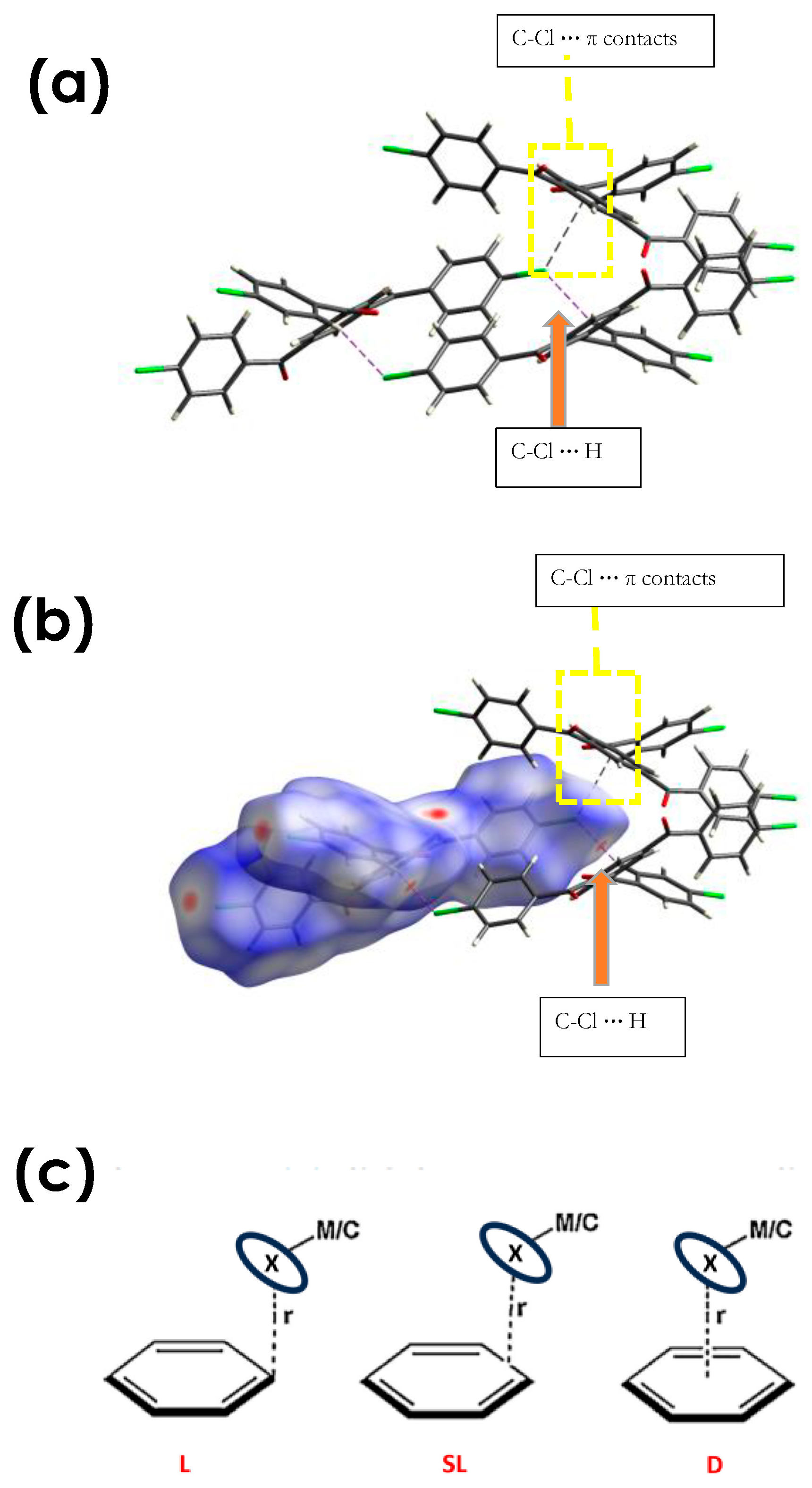
3.2.2. C-Cl···π (XB), and C-Cl···H, and Other Non-Covalent Interactions
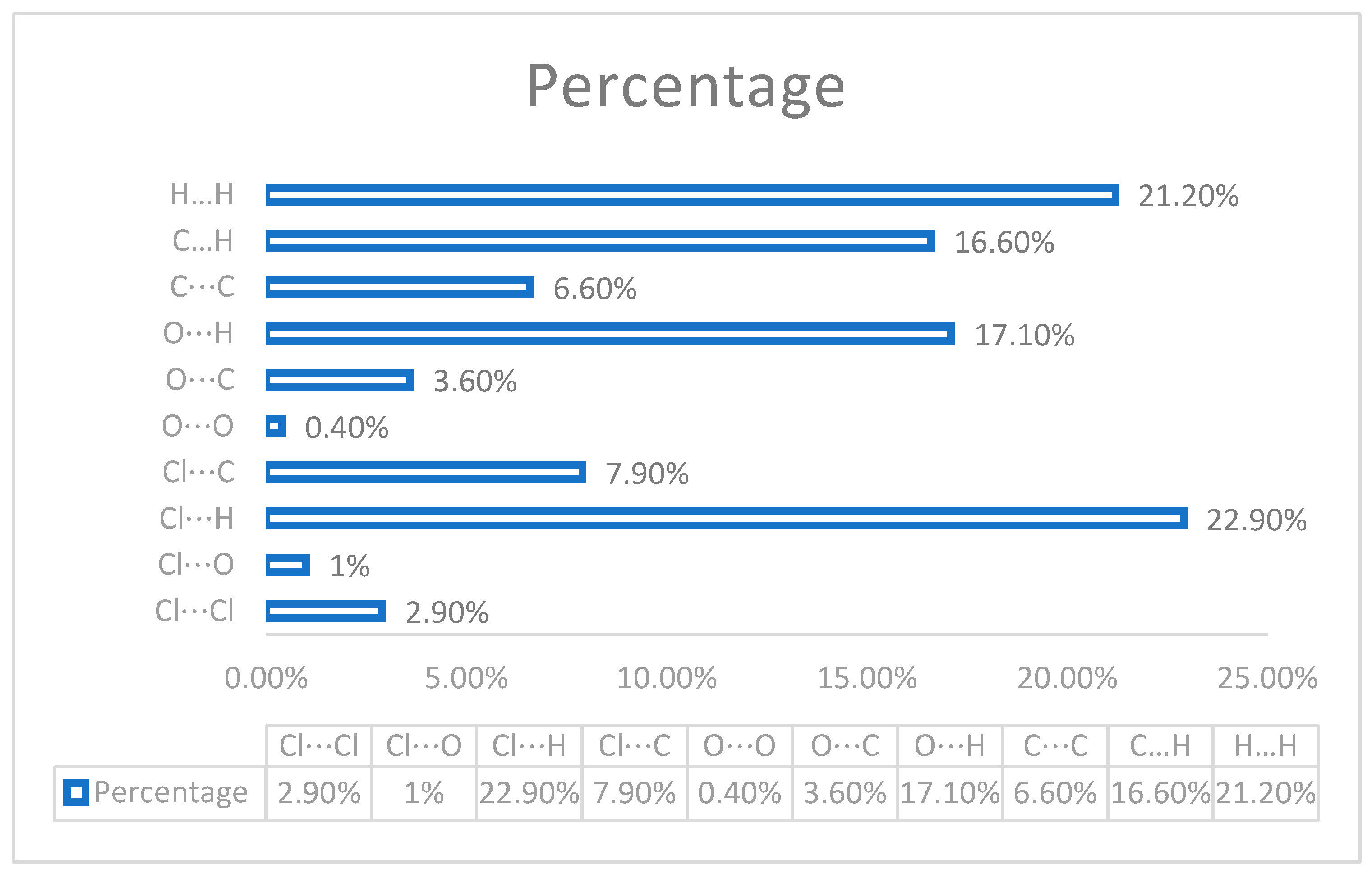
Halogen···π contacts are another common weak interaction that is frequently ignored due to the presence of other interactions [60]. Shishkin and Schneider [60,84] summarized this based on the location of the halogen atom relative to the aromatic plane: delocalized (D), semilocalized (SL) and localized (L), as shown in Figure 4c [60,84]. Compound A shows a localized halogen···π interaction (Type III halogen bonding) as shown in Figure 4a,b. Additionally, the same chlorine atom is involved in HB with another neighbouring molecule with a distant (C-Cl···H) HB interaction, [C--Cl···H= 162.26°, C-Cl···Cl= 127.60°, C-Cl···Cl =2.83 Å]. It should be noted that an HB interaction is observed with the chlorine atom, which is simultaneously participating in XB···π interactions. The HB interactions were observed to be perpendicular to the XB interactions, a phenomenon which might be proposed to arise from the distribution of electrostatic potential on the chlorine atom. It should be stated that the C-O···H distance in all interactions are shorter than the sum of the mean van der Waals radii of the two atoms 2.72 Å.
The unit cell of compound 3 shows four molecules. A simple analysis of the crystal packing of the compound 3 unit cell along the b-axis shows the presence of π–π aromatic interactions with a centroided to centroid distance of 3.846 Å between two neighbouring molecules, as exposed in Figure 5a. Additionally, each of the molecules involved in π–π stacking is involved in bi-halogen bonding with a neighboring molecule, forming a 1D network along the b- and c-axis as shown in Figure 5b.
In summary, the crystal structure for compound 3 (Figure 6) shows an interesting 3D network as a result of the halogen bond interaction (XB), C-Cl···π interaction, π–π stacking, halogen bonding, and other types of intermolecular interactions as demonstrated in Figure 6. It should be noted that two polymorphs of this compound are reported in the literature by Pigge et al., which shows a different characteristic in comparison with compound 3 [67]. In Pigge et al. (form A), each of the molecules in the unit cell contribute in the formation of 1D parallel chains interceded by the C-H···O (HB) interaction between carbonyl oxygens and phenyl hydrogen. Through aromatic C-H···Cl hydrogen bonding, these separate vertical chains are cross-linked in the horizontal direction and a Type II Cl···Cl interaction is presented. In Pigge et al. (polymorph I), moreover, two different C-H···Cl hydrogen-bonding interactions connect adjacent anti-parallel chains, resulting in the creation of a corrugated sheet-like structure. Form B’s solid-state structure differs significantly from that of form A. The unit cell contains a single unique molecule of three, and individual molecules are linked by a network of Cl···OCl and Type I (Cl···Cl) interactions, as well as OLC interactions, forming four vertical edges of a cube-like polyhedron.

3.3. Fingerprint

By measuring the distances de and di from the Hirshfeld surface and constructing a fingerprint plot (FP) based on this value, a three-dimensional representation of the intermolecular interactions in a crystal is obtained. A two-dimensional fingerprint (FP) of the crystal’s intermolecular interactions represents a unique full-color graphic for each crystal and summarizes the intricate information contained in a molecular crystal. The color of each point in the FP corresponds to the relative area of the surface occupied by that (de, di) pair, whereas the uncoloured points in the FP reflect no contribution to the surface. The colors in the plot vary from blue (the smallest contribution) to red (the largest contribution). Visualizing interactions in molecular crystals using Hirshfeld surface tools and 2D FP were analysed using Crystal Explorer (Version 17.5) [71,72,73,74,85].
Intermolecular contacts of compound 3 were plotted using 2D FP (Figure S7 and Figure 7) to provide additional evidence for the presence of XB interactions in compound 3 by calculating the percentage contribution of all interactions in the crystal structures. From a simple analysis, it immediately emerges that the Cl···H contacts have the highest contribution in comparison to all other interactions in the crystal structures. H···H and C···H interactions are responsible for the second and third contributions, respectively. Cl···C interactions show 7.9%, and Cl···Cl shows 2.9%. The final observation is the presence of ‘wings’, which are a typical representation of C-H···π contacts in the fingerprint plot: 16.6%.

3.4. Computational Chemistry

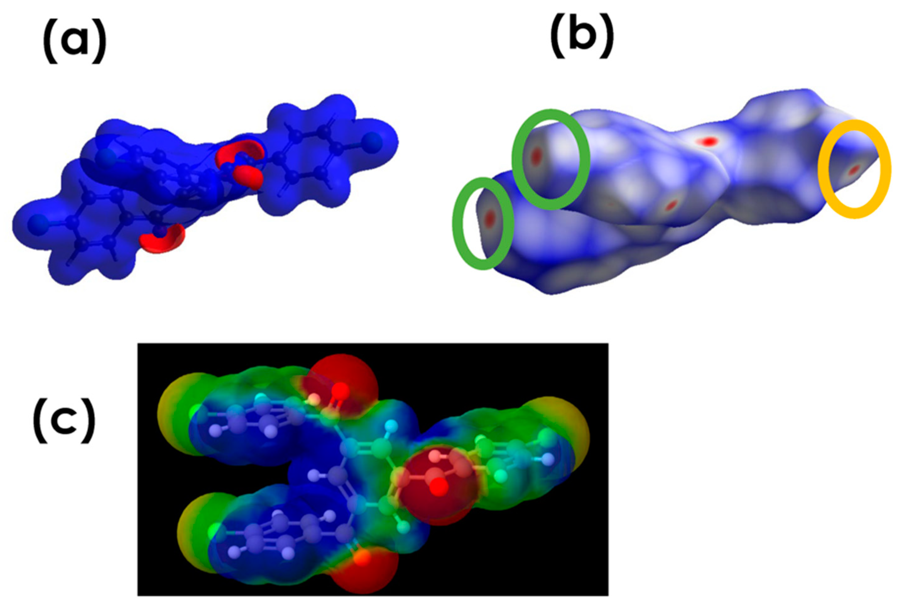
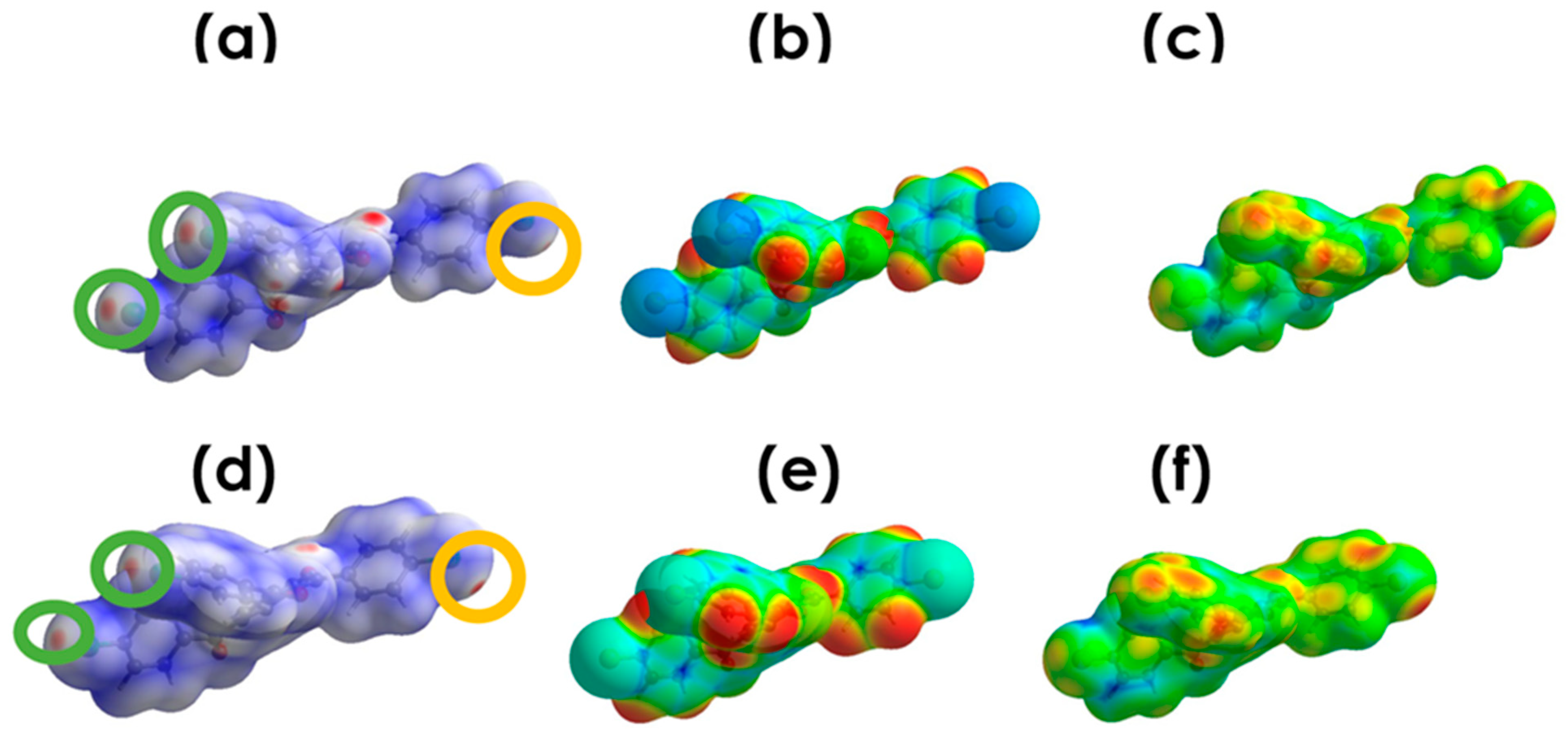
3.4.1. Electrostatic Potential

In Figure 8b, halogen bonding visualized using the electrostatic potential (ESP) is mapped onto Hirshfeld surfaces [71,86] by using wave functions that were obtained at the HF/STO-3G level [86]. These XB interactions are also reflected in the Hirshfeld surface mapped over the electrostatic potential displayed in Figure 8, where a blue region indicates a positive electrostatic potential and a red region indicates a negative electrostatic potential. It is clear that two red regions are observed around the two chlorine atoms, which formed double halogen bonding with two chlorine atoms in the neighboring molecule, forming a dimeric structure. The red spots are hightides in the green cycle. Additionally, faint red regions also appeared around the third chlorine atom corresponding to C-Cl···H, which is highlighted in yellow. Additionally, electrostatic potential (PE) mapped on Hirshfeld surface of the molecule is presented in Figure 9.

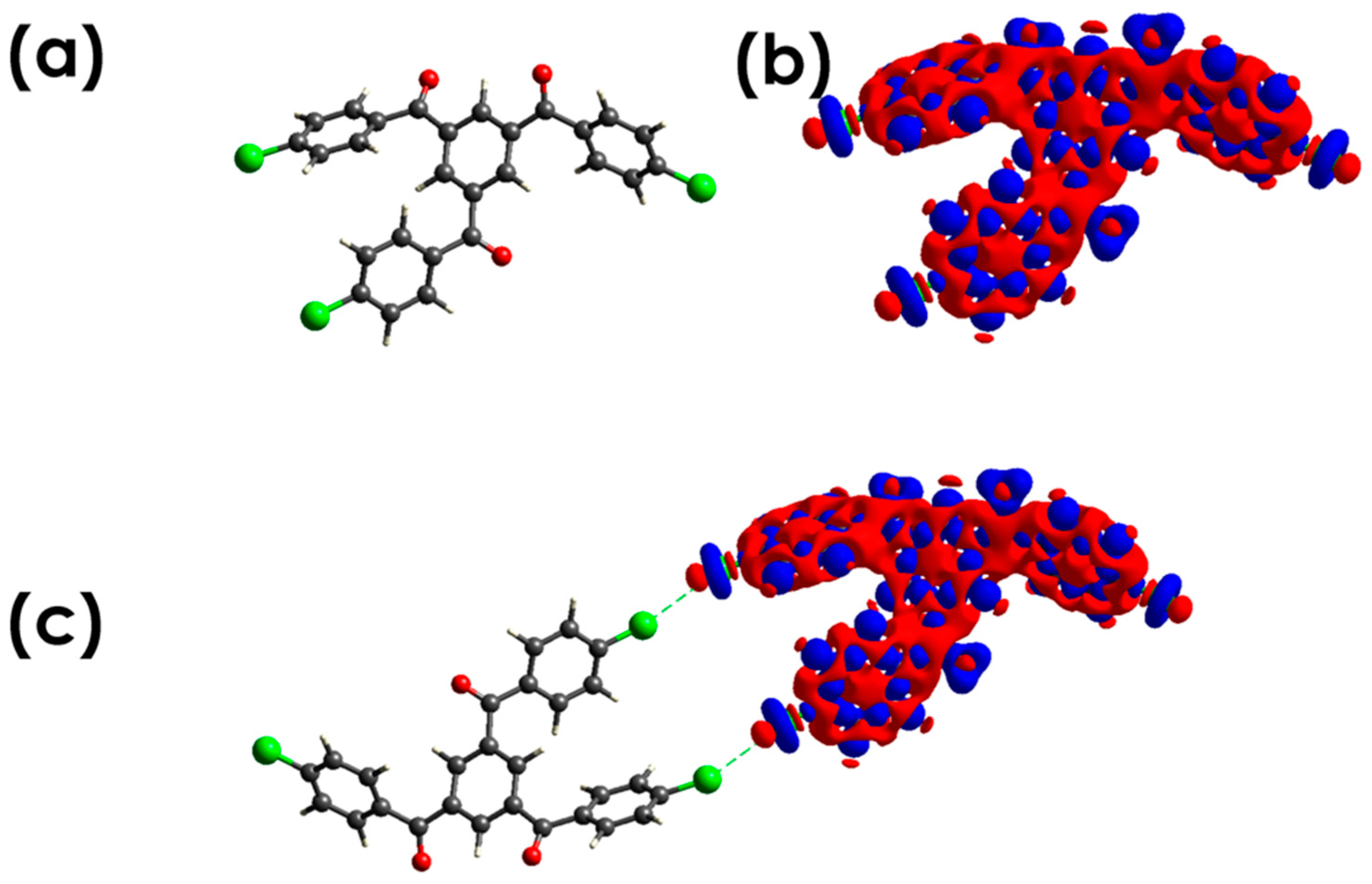
3.4.2. Deformation Density (DD) Maps

Crystal Explorer 17.5 [71,72,73,74] was used to compute 3D deformation density (DD) maps using the B3LYP/6-31G(d,p) wave function. The multipole modeling of X-ray data indicated the closed-shell nature of the interactions, where Cl···Cl Type I interactions might result as reduced repulsion by polar flattening effects as shown in Figure 10. A similar characteristic was reported for the Cl···Cl interaction by Row et al. [87].

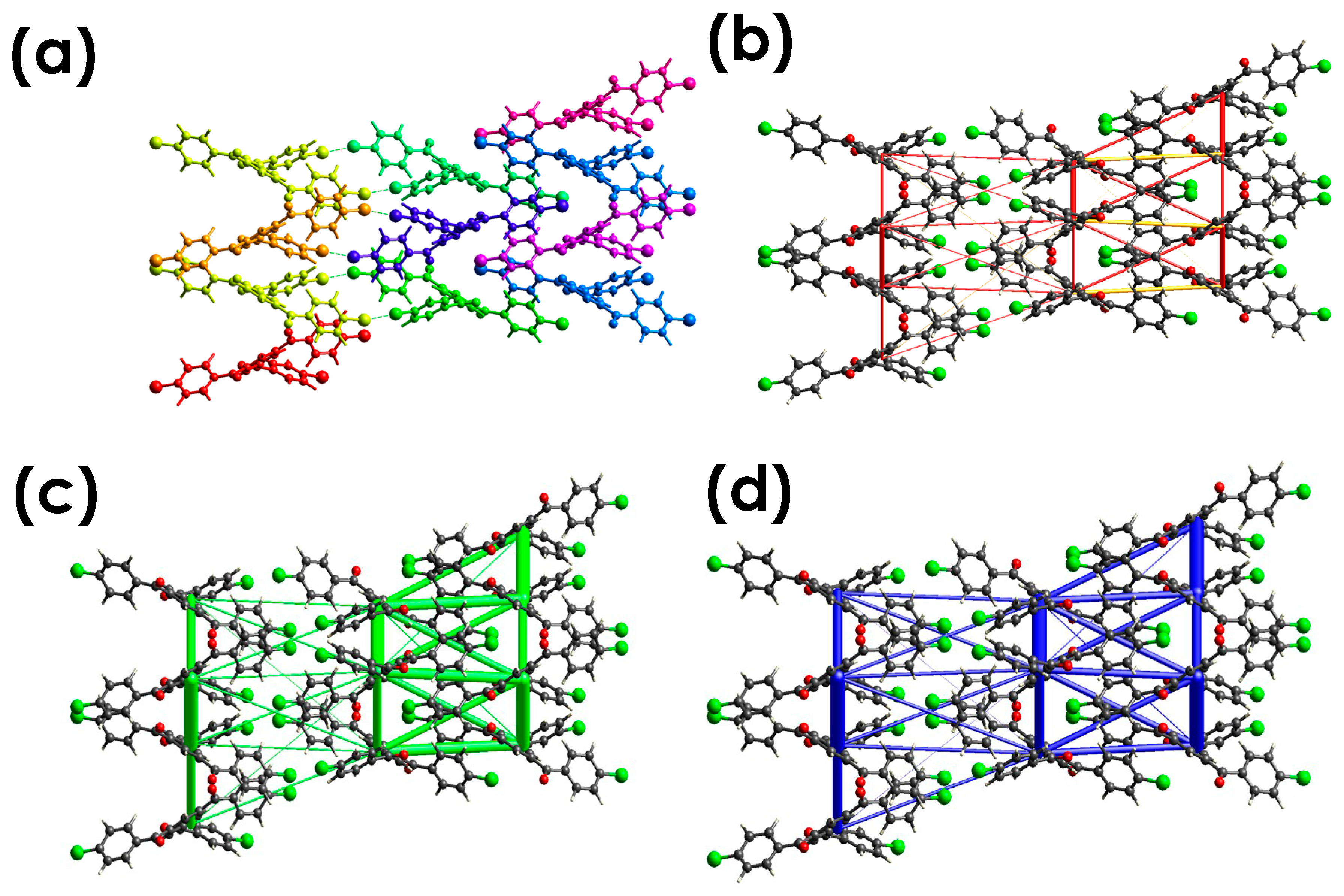
3.4.3. Energy Framework Calculations

Crystal Explorer 17.5 [71,72,73,74] was used to compute the pairwise interaction energy between the molecules within the crystal. To calculate the overall interaction energy, a molecular cluster with a radius of 3.8 was formed within the crystal around a selected molecule (Figure 11). The computation of interaction energy frameworks required the application of symmetry operations to build molecular wave functions and estimate electron densities of the chosen molecular cluster. The four energy components, electrostatic (E ele), polarization (E pol), dispersion (E dis) and exchange–repulsion (E rep), were obtained using the wave function calculated at the B3LYP/6-31G(d,p) level of theory. The total energy (Etot) was calculated using the CE-B3LYP/6-31G(d,p) energy model and the following scaling factors: K ele = 1.057, K pol = 0.740, K dis = 0.871, and Krep = 0.618 [77,88]. For the purpose of calculating interaction energy, the basis set CE-B3LYP/6-31G(d,p) [77] was selected since it matches a higher basis set that is compatible with the most recent version of the Crystal Explorer 17.5 program [71,72,73,74]. Table 1 summarizes the energy values. The crystallographic symmetry operations and their accompanying molecular interaction energies are shown in Table 2. R is the distance between molecular centroids, and N denotes the number of molecules at that distance. Energy values are given in kJ mol−1. These findings suggest that interactions between the center molecule and its neighbors can be classified into ten types. Figure 11a depicts the colors of the molecules in each of these categories. The energy frameworks depicted in Figure 11b–d use different colored cylinders to symbolize these energies. The energy framework was outlined as red cylinders for Eelec, green cylinders for Edis, and blue cylinders for Etot, as shown in Figure 8. The highest interaction energy (−54.9 kJ/mol) is obtained between the molecules with the best Cl···Cl intermolecular contact. The electrostatic component dominates this interaction.

4. Conclusions

The title compound benzene-1,3,5-triyltris((4-chlorophenyl)methanone) was synthesized, crystallized, and characterized using different techniques including 1H, and 13C, IR, and MS, and single-crystal X-ray diffraction. Halogen bonding can be attributed to the favorable interaction that exists between a halogen’s electropositive and electronegative atom, such as oxygen, or other halogen atoms. We have investigated the solid-state structure of a series of compound benzene-1,3,5-triyltris((4-chlorophenyl)methanone), where halogen···halogen, halogen···π, and other types of intermolecular interactions present the resulting structures. These interactions were identified and analyzed through distance, angles, Hirshfeld surface maps, two-dimensional (2D)-fingerprint analysis, and the percentage contribution for different kinds of non-covalent interaction.
The crystal structure of compound A exhibits Type I (Cl···Cl) halogen interaction short contact between two chlorine atoms attached to the para-position of two phenyl rings in one molecule and two chlorine atoms in a nearby molecule in the same position, resulting in a dimeric structure. In addition, the third chlorine atom is involved in a localized halogen···π interaction (Type III halogen bonding) with a neighbouring molecule. Additionally, the same chlorine atom is involved in HB with another neighbouring molecule which is perpendicular to the halogen interaction. Intermolecular contacts of compound A were plotted using 2D fingerprint, which provide additional evidence for the presence of XB interactions, with a percentage of 2.9% for Cl···Cl interactions. The shape index and curvedness surface over Hirshfeld were used to confirm the presence of such interactions. The electrostatic potential (ESP) mapped onto Hirshfeld surfaces, 3D molecular electrostatic potential (MEP), deformation density, and energy framework were used to confirm the presence of such interactions. The highest interaction energy (−54.9 kJ/mol) is obtained between the molecules with the best Cl···Cl intermolecular contact. The closed-shell structure of interactions was suggested by multipole modeling of X-ray data using a deformation density map, where Cl···Cl Type I interactions may result in reduced repulsion due to polar flattening effects. All analyses confirm the presence of halogen-bonding interactions in the title compound.

Supplementary Materials

The following supporting information can be downloaded at: https://www.mdpi.com/article/10.3390/cryst14010017/s1, Figure S1: MS. of Benzene-1,3,5-triyltris((4-chlorophenyl)methanone); Figure S2: IR. of Benzene-1,3,5-triyltris((4-chlorophenyl)methanone); Figure S3: 1H-NMR. of Benzene-1,3,5-triyltris((4-chlorophenyl)methanone); Figure S4: 13C-NMR. of Benzene-1,3,5-triyltris((4-chlorophenyl)methanone); Figure S5: Hirshfeld surfaces mapped of compound A with (1) di, (2) de, and (3) dnorm red spots corresponding to close contact; Figure S6: Hirshfeld surfaces of compound 3 mapped with (1) shape-index surfaces for compounds A along a-, b-, and c-axis. Shape-index surfaces (top, color code: hollow—red; bumps—blue). (2) Hirshfeld surfaces mapped with curvedness surfaces for compounds A along a-, b-, and c-axis. Curvedness surfaces (bottom, color code: edges—blue; flat regions—green); Figure S7: 2D fingerprint plots of compound A highlighting (a) all interactions, (b) Cl···Cl, (c) Cl···O, (d) Cl···H, (e) Cl···C, (f) O···O, (g) O···C. To provide context, the outline of the fingerprint is shown in grey; Figure S8: Electrostatic potential (PE) mapped on Hirshfeld surface of the molecule of A: (a) dnorm, (b) de, (c) di; Figure S9: Promolecule density mapped on Hirshfeld surface of the molecule of A: (a) dnorm, (b) de, (c) di. CCDC 2293563 contains the supplementary crystallographic data for this paper. These data can be obtained free of charge from the Cambridge Crystallographic Data Centre via www.ccdc.cam.ac.uk/data_request/cif (accessed on 7 July 2023).

Author Contributions

Conceptualization, H.M.H. and K.M.A.-Z.; methodology, H.M.H.; validation, S.A.-S., S.M.M. and H.A.A.-G.; formal analysis, A.I.A.-S.; investigation, S.M.M.; resources, K.M.A.-Z.; writing—original draft preparation, writing, review, editing, and visualizing, all authors; supervision, K.M.A.-Z.; project administration, K.M.A.-Z. All authors have read and agreed to the published version of the manuscript.

Funding

This research received no external funding.

Data Availability Statement

The data presented in this study are available in this article and Supplementary Materials.

Acknowledgments

The authors thank the University of Jeddah for its technical support.

Conflicts of Interest

The authors declare no conflicts of interest.

References

  1. Desiraju, G.R. Crystal engineering: A holistic view. Angew. Chem. Int. Ed. 2007, 46, 8342–8356. [Google Scholar] [CrossRef] [PubMed]
  2. Aakeroy, C.B.; Champness, N.R.; Janiak, C. Recent advances in crystal engineering. CrystEngComm 2010, 12, 22. [Google Scholar] [CrossRef]
  3. Blunt, M.O.; Hu, Y.; Toft, C.W.; Slater, A.G.; Lewis, W.; Champness, N.R. Controlling the Two-Dimensional Self-Assembly of Functionalized Porphyrins via Adenine–Thymine Quartet Formation. J. Phys. Chem. C 2018, 122, 26070. [Google Scholar] [CrossRef]
  4. Räisänen, M.T.; Slater née Phillips, A.G.; Champness, N.R.; Buck, M. Effects of Pore Modification on the Templating of Guest Molecules in a 2D Honeycomb Network. Chem. Sci. 2012, 3, 84–92. [Google Scholar] [CrossRef]
  5. Theobald, J.A.; Oxtoby, N.S.; Phillips, M.A.; Champness, N.R.; Beton, P.H. Controlling Molecular Deposition and Layer Structure with Supramolecular Surface Assemblies. Nature 2003, 424, 1029. [Google Scholar] [CrossRef]
  6. Blunt, M.O.; Russell, J.C.; Gimenez-Lopez, M.d.C.; Taleb, N.; Lin, X.; Schröder, M.; Champness, N.R.; Beton, P.H. Guest-Induced Growth of a Surface-Based Supramolecular Bilayer. Nat. Chem. 2011, 3, 74. [Google Scholar] [CrossRef]
  7. Slater, A.G.; Hu, Y.; Yang, L.; Argent, S.P.; Lewis, W.; Blunt, M.O.; Champness, N.R. Thymine functionalised porphyrins, synthesis and heteromolecular surface-based self-assembly. Chem. Sci. 2015, 6, 1562. [Google Scholar] [CrossRef]
  8. Gutzler, R.; Fu, C.; Dadvand, A.; Hua, Y.; MacLeod, J.M.; Rosei, F.; Perepichka, D.F. Halogen bonds in 2D supramolecular self-assembly of organic semiconductors. Nanoscale 2012, 4, 5965. [Google Scholar] [CrossRef]
  9. Yoon, J.K.; Son, W.-J.; Chung, K.-H.; Kim, H.; Han, S.; Kahng, S.-J. Visualizing Halogen Bonds in Planar Supramolecular Systems. J. Phys. Chem. C 2011, 115, 2297. [Google Scholar] [CrossRef]
  10. Metrangolo, P.; Resnati, G. Halogen Bonding: A Paradigm in Supramolecular Chemistry. Chem.—Eur. J. 2001, 7, 2511. [Google Scholar] [CrossRef]
  11. Brammer, L.; Minguez Espallargas, G.; Libri, S. Combining metals with halogen bonds. CrystEngComm 2008, 10, 1712–1727. [Google Scholar] [CrossRef]
  12. Metrangolo, P.; Pilati, T.; Resnati, G. Halogen bonding and other noncovalent interactions involving halogens: A terminology issue. CrystEngComm 2006, 8, 946. [Google Scholar] [CrossRef]
  13. Frontera, A.; Quiñonero, D.; Deyà, P.M. Cation–π and anion–π interactions. Wiley Interdisciplinary Reviews: Comput. Mol. Sci. 2011, 1, 440. [Google Scholar] [CrossRef]
  14. Steed, J.W.; Turner, D.R.; Wallace, K. Core Concepts in Supramolecular Chemistry and Nanochemistry; John Wiley & Sons: Hoboken, NJ, USA, 2007. [Google Scholar]
  15. Blunt, M.O.; Adisoejoso, J.; Tahara, K.; Katayama, K.; Van der Auweraer, M.; Tobe, Y.; Feyter, S.D. Temperature-Induced Structural Phase Transitions in a Two-Dimensional Self-Assembled Network. J. Am. Chem. Soc. 2013, 135, 12068. [Google Scholar] [CrossRef] [PubMed]
  16. Yokoyama, T.; Yokoyama, S.; Kamikado, T.; Okuno, Y.; Mashiko, S. Selective assembly on a surface of supramolecular aggregates with controlled size and shape. Nature 2001, 413, 619. [Google Scholar] [CrossRef]
  17. Böhringer, M.; Morgenstern, K.; Schneider, W.-D.; Berndt, R. Separation of a Racemic Mixture of Two-Dimensional Molecular Clusters by Scanning Tunneling Microscopy. Angew. Chem. Int. Ed. Engl. 1999, 38, 821. [Google Scholar] [CrossRef]
  18. Sarkar, N.; Sinha, A.S.; Aakeröy, C.B. Systematic investigation of hydrogen-bond propensities for informing co-crystal design and assembly. CrystEngComm 2019, 21, 6048–6055. [Google Scholar] [CrossRef]
  19. Kumar, A.; Kumar, S.; Nanda, A. A review about regulatory status and recent patents of pharmaceutical co-crystals. Adv. Pharm. Bull. 2018, 8, 355. [Google Scholar] [CrossRef]
  20. Sandhu, B.; Sinha, A.S.; Desper, J.; Aakeröy, C.B. Modulating the physical properties of solid forms of urea using co-crystallization technology. Chem. Comm. 2018, 54, 4657. [Google Scholar] [CrossRef]
  21. Fourmigué, M.; Dhaka, A. Chalcogen bonding in crystalline diselenides and selenocyanates: From molecules of pharmaceutical interest to conducting materials. Coord. Chem. Rev. 2020, 403, 213084. [Google Scholar] [CrossRef]
  22. Mahmudov, K.T.; Kopylovich, M.N.; da Silva, M.F.C.G.; Pombeiro, A.J.L. Chalcogen bonding in synthesis, catalysis and design of materials. Dalton Trans. 2017, 46, 10121. [Google Scholar] [CrossRef] [PubMed]
  23. Brammer, L. Halogen bonding, chalcogen bonding, pnictogen bonding, tetrel bonding: Origins, current status and discussion. Faraday Discuss. 2017, 203, 485. [Google Scholar] [CrossRef] [PubMed]
  24. Ding, X.; Tuikka, M.; Haukka, M.; Benedict, J.B. Recent Advances in Crystallography; IntechOpen: London, UK, 2012; p. 143. [Google Scholar]
  25. Rosokha, S.V.; Neretin, I.S.; Rosokha, T.Y.; Hecht, J.; Kochi, J.K. Charge-Transfer Character of Halogen Bonding: Molecular Structures and Electronic Spectroscopy of Carbon Tetrabromide and Bromoform Complexes with Organic σ- and π-Donors. Heteroat. Chem. 2006, 17, 449. [Google Scholar] [CrossRef]
  26. Laurence, C.; Graton, J.; Berthelot, M.; El Ghomari, M.J. The Diiodine Basicity Scale: Toward a General Halogen-Bond Basicity Scale. Chem. Eur. J. 2011, 17, 10431. [Google Scholar] [CrossRef]
  27. Cavallo, G.; Metrangolo, P.; Milani, R.; Pilati, T.; Priimagi, A.; Resnati, G.; Terraneo, G. The Halogen Bond. Chem. Rev. 2016, 116, 2478–2601. [Google Scholar] [CrossRef] [PubMed]
  28. Karan, N.K.; Arunan, E. Chlorine Bond Distances in ClF and Cl2 Complexes. J. Mol. Struct. 2004, 688, 203–205. [Google Scholar] [CrossRef]
  29. Raghavendra, B.; Arunan, E. Unpaired and Sigma Bond Electrons as H, Cl, and Li Bond Acceptors: An Anomalous One-Electron Blue-Shifting Chlorine Bond. J. Phys. Chem. A 2007, 111, 9699. [Google Scholar] [CrossRef] [PubMed]
  30. Chopra, D.; Row, T.N.G. Role of Organic Fluorine in Crystal Engineering. CrystEngComm 2011, 13, 2175. [Google Scholar] [CrossRef]
  31. Laurence, C.; Graton, J.; Gal, J.F. An Overview of Lewis Basicity and Affinity Scales. J. Chem. Educ. 2011, 88, 1651. [Google Scholar] [CrossRef]
  32. Lu, Y.X.; Zou, J.W.; Yu, Q.S.; Jiang, Y.J.; Zhao, W.N. Ab Initio Investigation of Halogen Bonding Interactions Involving Fluorine as an Electron Acceptor. Chem. Phys. Lett. 2007, 449, 6–10. [Google Scholar] [CrossRef]
  33. Metrangolo, P.; Pilati, T.; Terraneo, G.; Biella, S.; Resnati, G. Anion coordination and anion-templated assembly under halogen bonding control. CrystEngComm 2009, 11, 1187. [Google Scholar] [CrossRef]
  34. Mukherjee, A.; Tothadi, S.; Desiraju, G.R. Halogen Bonds in Crystal Engineering: Like Hydrogen Bonds yet Different. Acc. Chem. Res. 2014, 47, 2514. [Google Scholar] [CrossRef] [PubMed]
  35. Guan, L.; Disney, M.D. Covalent Small-Molecule–RNA Complex Formation Enables Cellular Profiling of Small-Molecule–RNA Interactions. Angew. Chem. Int. Ed. 2013, 52, 10010. [Google Scholar] [CrossRef] [PubMed]
  36. Gilday, L.C.; Lang, T.; Caballero, A.; Costa, P.J.; Félix, V.; Beer, P.D. A Catenane Assembled through a Single Charge-Assisted Halogen Bond. Angew. Chem. Int. Ed. 2013, 52, 4356. [Google Scholar] [CrossRef] [PubMed]
  37. Miao, X.; Cai, Z.; Zou, H.; Li, J.; Zhang, S.; Ying, L.; Deng, W. Achieving halogen bonding enhanced ultra-highly efficient AIE and reversible mechanochromism properties of TPE-based luminogens: Position of bromine substituents. J. Mater. Chem. C 2022, 10, 8390. [Google Scholar] [CrossRef]
  38. Wilcken, R.; Zimmermann, M.O.; Lange, A.; Joerger, A.C.; Boeckler, F.M. Principles and Applications of Halogen Bonding in Medicinal Chemistry and Chemical Biology. J. Med. Chem. 2013, 56, 1363. [Google Scholar] [CrossRef]
  39. D’aléo, A.; Saul, A.; Attaccalite, C.; Fages, F. Influence of halogen substitution on aggregation-induced near infrared emission of borondifluoride complexes of 2′-hydroxychalcones. Mater. Chem. Front. 2019, 3, 86. [Google Scholar]
  40. Politzer, P.; Murray, J.S.; Clark, T. Halogen bonding: An electrostatically-driven highly directional noncovalent interaction. Phys. Chem. Chem. Phys. 2010, 12, 7748. [Google Scholar] [CrossRef]
  41. Metrangolo, P.; Meyer, F.; Pilati, T.; Resnati, G.; Terraneo, G. Halogen Bonding in Supramolecular Chemistry. Angew. Chem. Int. Ed. 2008, 47, 6114. [Google Scholar] [CrossRef]
  42. Metrangolo, P.; Neukirch, H.; Pilati, T.; Resnati, G. Halogen Bonding Based Recognition Processes:  A World Parallel to Hydrogen Bonding. Acc. Chem. Res. 2005, 38, 386. [Google Scholar] [CrossRef]
  43. Robertson, C.C.; Wright, J.S.; Carrington, E.J.; Perutz, R.N.; Hunter, C.A.; Brammer, L. Hydrogen bonding vs. halogen bonding: The solvent decides. Chem. Sci. 2017, 8, 5392. [Google Scholar] [PubMed]
  44. Metrangolo, P.; Murray, J.S.; Pilati, T.; Politzer, P.; Resnati, G.; Terraneo, G. Fluorine-centered halogen bonding: A factor in recognition phenomena and reactivity. Cryst. Growth Des. 2011, 11, 4238. [Google Scholar] [CrossRef]
  45. Costa, P.J. The halogen bond: Nature and applications. Phys. Sci. Rev. 2017, 2, 20170136. [Google Scholar] [CrossRef]
  46. Atwood, J.L.; Steed, J.W. Encyclopedia of Supramolecular Chemistry; CRC Press: Boca Raton, FL, USA, 2004. [Google Scholar]
  47. Cametti, M.; Crousse, B.; Metrangolo, P.; Milani, R.; Resnati, G. The Fluorous Effect in Biomolecular Applications. Chem. Soc. Rev. 2012, 41, 31. [Google Scholar] [CrossRef] [PubMed]
  48. Pavan, M.S.; Durga Prasad, K.; Guru Row, T.N. Halogen bonding in fluorine: Experimental charge density study on intermolecular F···F and F···S donor–acceptor contacts. Chem. Comm. 2013, 49, 7558. [Google Scholar] [CrossRef] [PubMed]
  49. Vartanian, M.; Lucassen, A.C.B.; Shimon, L.J.W.; Van Der Boom, M.E. Cocrystallization of a tripyridyl donor with perfluorinated iodobenzene derivatives: Formation of different n··· I halogen bonds determining network vs plain packing crystals. Cryst. Growth Des. 2008, 8, 786. [Google Scholar] [CrossRef]
  50. Christopherson, J.C.; Topić, F.; Barrett, C.J.; Friščić, T. Halogen-Bonded Cocrystals as Optical Materials: Next-Generation Control over Light–Matter Interactions. Cryst. Growth Des. 2018, 18, 1245. [Google Scholar] [CrossRef]
  51. Kitagawa, S.; Uemura, K. Dynamic porous properties of coordination polymers inspired by hydrogen bonds. Chem. Soc. Rev. 2005, 34, 109. [Google Scholar] [CrossRef]
  52. Raatikainen, K.; Rissanen, K. Breathing molecular crystals: Halogen- and hydrogen-bonded porous molecular crystals with solvent induced adaptation of the nanosized channels. Chem. Sci. 2012, 3, 1235. [Google Scholar] [CrossRef]
  53. Turunen, L.; Beyeh, N.K.; Pan, F.; Valkonen, A.; Rissanen, K. Tetraiodoethynyl resorcinarene cavitands as multivalent halogen bond donors. Chem. Commun. 2014, 50, 15920. [Google Scholar] [CrossRef]
  54. Shankar, S.; Chovnik, O.; Shimon, L.J.W.; Lahav, M.; van der Boom, M.E. Directed Molecular Structure Variations of Three-Dimensional Halogen-Bonded Organic Frameworks (XBOFs). Cryst. Growth Des. 2018, 18, 1967. [Google Scholar] [CrossRef]
  55. Meazza, L.; Foster, J.A.; Fucke, K.; Metrangolo, P.; Resnati, G.; Steed, J.W. Halogen-bonding-triggered supramolecular gel formation. Nat. Chem. 2013, 5, 42. [Google Scholar] [CrossRef]
  56. Lascialfari, L.; Resnati, G.; Metrangolo, P. 704—Halogen-Bonded Cocrystals. In Comprehensive Supramolecular Chemistry, 2nd ed.; Atwood, J.L., Ed.; Elsevier: Oxford, UK, 2017; pp. 49–72. [Google Scholar]
  57. Sakurai, T.; Sundaralingam, M.; Jeffrey, G.A. A Nuclear Quadrupole Resonance and X-Ray Study of Crystal Structure of 2, 5- Dichloroaniline. Acta Crystallogr. 1963, 16, 354. [Google Scholar] [CrossRef]
  58. Sarma, J.A.R.P.; Desiraju, G.R. The chloro-substituent as a steering group: A comparative study of non-bonded interactions and hydrogen bonding in crystalline chloro-aromatics. Chem. Phys. Lett. 1985, 117, 160. [Google Scholar] [CrossRef]
  59. Nangia, A.; Desiraju, G.R. Supramolecular Synthons and Pattern Recognition. In Design of Organic Solids; Weber, E., Aoyama, Y., Caira, M.R., Desiraju, G.R., Glusker, J.P., Hamilton, A.D., Weber, E., Meléndez, R.E., Eds.; Springer: Berlin/Heidelberg, Germany, 1998; pp. 57–95. [Google Scholar]
  60. Li, B.; Zang, S.-Q.; Wang, L.-Y.; Mak, T.C.W. Halogen bonding: A powerful, emerging tool for constructing high-dimensional metal-containing supramolecular networks. Coord. Chem. Rev. 2016, 308, 1–21. [Google Scholar] [CrossRef]
  61. Mahmudov, K.T.; Kopylovich, M.N.; da Silva, M.F.C.G.; Pombeiro, A.J.L. Non-covalent interactions in the synthesis of coordination compounds: Recent advances. Coord. Chem. Rev. 2017, 345, 54. [Google Scholar] [CrossRef]
  62. Ibrahim, M.A.A.; Moussa, N.A.M. Unconventional type III halogen··· halogen interactions: A quantum mechanical elucidation of σ-hole··· σ-hole and di-σ-hole interactions. ACS Omega 2020, 5, 21824. [Google Scholar] [CrossRef] [PubMed]
  63. Hassanin, H. Development of Novel Fluoreescent Dye Molecules Based on BODIPY. Ph.D. Thesis, University of Nottingham, Nottingham, UK, March 2019. [Google Scholar]
  64. Liu, F.-S.; Liu, X.-H.; Ye, K.-Z.; Shen, D.-S. Facile Synthesis of 1,3,5-Triaroylbenzenes by Direct Cyclotrimerization of Ketone Enolates. Synth. Commun. 2013, 43, 1640. [Google Scholar] [CrossRef]
  65. Pigge, F.C.; Vangala, V.R.; Swenson, D.C.; Rath, N.P. Examination of halogen bonding interactions in electronically distinct but structurally related tris (haloarenes). Cryst. Growth Des. 2010, 10, 224. [Google Scholar] [CrossRef]
  66. Pigge, F.C.; Dighe, M.K.; Rath, N.P. Self-assembly of sticky TABs: Inclusion complexes and hydrates from 1,3,5-tris (4-hydroxybenzoyl) benzene. Cryst. Growth Des. 2006, 6, 2732. [Google Scholar] [CrossRef]
  67. Kumar, V.S.S.; Pigge, F.C.; Rath, N.P. Polymorphism in 1, 3, 5-triaroylbenzenes: Structural characterization of concomitant polymorphs obtained from 1, 3, 5-tris (4-chlorobenzoyl) benzene. CrystEngComm 2004, 6, 102. [Google Scholar] [CrossRef]
  68. Kumar, V.S.S.; Pigge, F.C.; Rath, N.P. Polymorphism and pseudopolymorphism in the triaroylbenzene derivative 1,3,5-tris (4-cyanobenzoyl) benzene. Cryst. Growth Des. 2004, 4, 1217. [Google Scholar] [CrossRef]
  69. van Terwingen, S.; Wang, R.; Englert, U. Three for the Price of One: Concomitant I···N, I···O, and I···π Halogen Bonds in the Same Crystal Structure. Molecules 2022, 27, 7550. [Google Scholar] [CrossRef]
  70. Hassanain, H.; Davies, E.S.; Lewis, W.; Kays, D.L.; Champness, N.R. Morpholino-Substituted BODIPY Species: Synthesis, Structure and Electrochemical Studies. Crystals 2020, 10, 36. [Google Scholar] [CrossRef]
  71. Spackman, M.A.; Jayatilaka, D. Hirshfeld surface analysis. CrystEngComm 2009, 11, 19. [Google Scholar] [CrossRef]
  72. Spackman, P.R.; Turner, M.J.; McKinnon, J.J.; Wolff, S.K.; Grimwood, D.J.; Jayatilaka, D.; Spackman, M.A. CrystalExplorer: A program for Hirshfeld surface analysis, visualization and quantitative analysis of molecular crystals. J. Appl. Crystallogr. 2021, 54, 1006. [Google Scholar] [CrossRef] [PubMed]
  73. Spackman, M.A.; McKinnon, J.J. Fingerprinting intermolecular interactions in molecular crystals. CrystEngComm 2002, 4, 378. [Google Scholar] [CrossRef]
  74. McKinnon, J.J.; Mitchell, A.S.; Spackman, M.A. Hirshfeld Surfaces: A New Tool for Visualising and Exploring Molecular Crystals. Chem.—Eur. J. 1998, 4, 2136. [Google Scholar] [CrossRef]
  75. McKinnon, J.J.; Jayatilaka, D.; Spackman, M.A. Towards quantitative analysis of intermolecular interactions with Hirshfeld surfaces. Chem. Comm. 2007, 3814, 2136–2141. [Google Scholar] [CrossRef]
  76. Smith, T.J. MOLView: A program for analyzing displaying atomic structures on the Macintosh personal computer. J. Mol. Graph. 1995, 13, 122. [Google Scholar] [CrossRef]
  77. Mackenzie, C.F.; Spackman, P.R.; Jayatilaka, D.; Spackman, M.A. CrystalExplorer model energies and energy frameworks: Extension to metal coordination compounds, organic salts, solvates and open-shell systems. IUCrJ 2017, 4, 575. [Google Scholar] [CrossRef] [PubMed]
  78. Grimme, S. Semiempirical GGA-type density functional constructed with a long-range dispersion correction. J. Comput. Chem. 2006, 27, 1787. [Google Scholar] [CrossRef] [PubMed]
  79. Tan, S.L.; Jotani, M.M.; Tiekink, E.R.T. Utilizing Hirshfeld surface calculations, non-covalent interaction (NCI) plots and the calculation of interaction energies in the analysis of molecular packing. Acta Crystallogr. E Crystallogr. 2019, 75, 308. [Google Scholar] [CrossRef] [PubMed]
  80. Bakheit, A.H.; Abuelizz, H.A.; Al-Salahi, R. Hirshfeld Surface Analysis and Density Functional Theory Calculations of 2-Benzyloxy-1,2,4-triazolo [1,5-a] quinazolin-5 (4 H)-one: A Comprehensive Study on Crystal Structure, Intermolecular Interactions, and Electronic Properties. Crystals 2023, 13, 1410. [Google Scholar] [CrossRef]
  81. Kamat, V.; Kumara, K.; Naik, K.; Kotian, A.; Netalkar, P.; Shivalingegowda, N.; Neratur, K.L.; Revankar, V. [Dichlorido (2-(2-(1H-benzo [d] thiazol-2-yl) hydrazono) propan-1-ol) Cu (II)]: Crystal structure, Hirshfeld surface analysis and correlation of its ESI-MS behavior with [Dichlorido 3-(hydroxyimino)-2-butanone-2-(1H-benzo [d] thiazol-2-yl) hydrazone Cu (II)]. J. Mol. Struct. 2017, 1149, 357. [Google Scholar]
  82. Kumara, K.; Jyothi, M.; Kouser, S.; Kumar, A.H.U.; Warad, I.; Khanum, S.A.; Lokanath, N.K. Structural investigations and theoretical insights of a polymethoxy chalcone derivative: Synthesis, crystal structure, 3D energy frameworks and SARS CoV-2 docking studies. J. Mol. Struct. 2023, 1272, 134226. [Google Scholar] [CrossRef]
  83. Abdel-Khalik, M.M.; Elnagdi, M.H. Enaminones in organic synthesis: A novel synthesis of 1,3,5-trisubstituted benzene derivatives and of 2-substituted-5-aroylpyridines. Synth. Commun. 2002, 32, 159. [Google Scholar] [CrossRef]
  84. Schollmeyer, D.; Shishkin, O.V.; Rühl, T.; Vysotsky, M.O. OH–π and halogen–π interactions as driving forces in the crystal organisations of tri-bromo and tri-iodo trityl alcohols. CrystEngComm 2008, 10, 715. [Google Scholar] [CrossRef]
  85. Wolff, S.K.; Grimwood, D.J.; McKinnon, J.J.; Turner, M.J.; Jayatilaka, D.; Spackman, M.A. Crystal Explorer 3.0; University of Western Australia: Perth, Australia, 2012. [Google Scholar]
  86. Spackman, M.A.; McKinnon, J.J.; Jayatilaka, D. Electrostatic potentials mapped on Hirshfeld surfaces provide direct insight into intermolecular interactions in crystals. CrystEngComm 2008, 10, 377. [Google Scholar] [CrossRef]
  87. Thomas, S.P.; Dikundwar, A.G.; Sarkar, S.; Pavan, M.S.; Pal, R.; Hathwar, V.R.; Guru Row, T.N. The relevance of experimental charge density analysis in unraveling noncovalent interactions in molecular crystals. Molecules 2022, 27, 3690. [Google Scholar] [CrossRef]
  88. Turner, M.J.; Grabowsky, S.; Jayatilaka, D.; Spackman, M.A. Accurate and efficient model energies for exploring intermolecular interactions in molecular crystals. J. Phys. Chem. Lett. 2014, 5, 4249. [Google Scholar] [CrossRef] [PubMed]
Figure 1. Benzene-1,3,5-triyltris((4-chlorophenyl)methanone) compound studied in this paper.
Crystals 14 00017 g001
Scheme 1. Synthesis compound A.
Crystals 14 00017 sch001
Figure 2. Hirshfeld surfaces for compounds A showing interaction in the crystal structure. (a) Shape index surfaces: hollows = red colors; bumps = blue colors. (b) Curvedness surfaces: edges = blue color; flat region = green color. (c) Hirshfield surfaces, color scale in between −0.18 au (blue) and 1.2 au (red). C-O···H hydrogen-bonding interaction are highlighted in red. C-Cl···Cl halogen-bonding interaction are highlighted in pink, and C-Cl···π halogen-bonding interaction are highlighted in yellow. Atom colors: carbon atoms = grey, oxygen atoms = red, chlorine atoms = green.
Crystals 14 00017 g002
Figure 3. (a) Views of the single-crystal X-ray structures of A showing (C-Cl···Cl) XB interaction; the distance is measured in the top. (b) The XB angle was measured in the bottom. (c) HS calculated for A showing close (C-Cl···Cl) contact, which is highlighted in pink. Color scale in between −0.18 au (blue) and 1.2 au (red). Atom colors: carbon atoms = grey, oxygen atoms = red, chlorine atoms = green.
Crystals 14 00017 g003
Figure 4. (a) Crystal structure of 3. (b) HS calculated for 3, showing close (C-Cl···π) contact, highlighted in yellow, and C-Cl···H (HB). The colour scale is between −0.18 au (blue) and 1.2 au (red). The C-Cl···π contacts are highlighted in yellow color, and orange arrows were used to identify C-Cl···H hydrogen-bonding interaction. Atom colors: carbon atoms = grey, oxygen atoms = red, chlorine atoms = green. (c) Schematic representations of different types of halogen···π interactions, where L = localized, SL = semi-localized, and D = de-localized.
Crystals 14 00017 g004
Figure 5. (a) Unit cell of 3 viewed along the b-axis highlighted the presence of Cl···Cl halogen bonding dimer (identified using green arrows), and the presence of π···π stacking is highlighted in dark blue. (b) 1D chain formed by Cl···Cl XB dimer and the presence of π···π stacking for compound 3. H atoms are not show for clarity. Atom colors: carbon atoms = grey, oxygen atoms = red, chlorine atoms = green.
Crystals 14 00017 g005
Figure 6. Crystal-packing diagram of 3 viewed along the (a) a-axis, (b) b-axis, and (c) c-axis. H atoms are not show for clarity. Intermolecular interaction presence is C-Cl···Cl, C-C···H, C-Cl···π, and other interaction. Atom colors: carbon atoms = grey, oxygen atoms = red, chlorine atoms = green.
Crystals 14 00017 g006
Figure 7. Percentage contributions of individual intermolecular interactions to the Hirshfeld surfaces of compound 3.
Crystals 14 00017 g007
Figure 8. (a) Electrostatic potential (ESP). (b) Electrostatic potential (ESP) mapped onto Hirshfeld surfaces (40, 47) by using wave functions were obtained at the HF/STO-3G level (47). Red spots are hightides in green cycle, which form dimeric structure with neighboring chlorine atoms. The faint red regions correspond to C-Cl···H, which are highlighted in yellow. (c) The 3D model map of molecular electrostatic potential (MEP) of 3 is generated using the Moleview Program (76), where blue color = positive, red = negative electrostatic potential surface.
Crystals 14 00017 g008
Figure 9. Electrostatic potential (PE) mapped on Hirshfeld surface of the molecule of 3: (a) dnorm, (b) de, (c) di. Promolecule density mapped on Hirshfeld surface of the molecule of 3: (d) dnorm, (e) de, (f) di. In dnorm, red spots are hightides in green cycle, which form dimeric structure with neighbouring chlorine atoms. The faint red regions correspond to C-Cl···H, which are highlighted in yellow.
Crystals 14 00017 g009
Figure 10. (a) Compound 3. (b) 3D deformation density (DD) maps for 3 shows the presence of charge depletion (CD) in red and charge concentration (CC) in blue. (c) 3D deformation density (DD) maps for 3, and the neighboring molecule forming dimeric structure. Atom colors: carbon atoms = grey, oxygen atoms = red, chlorine atoms = green.
Crystals 14 00017 g010
Figure 11. (a) Illustration of molecular interactions in a cluster with a radius of 3.8 Å between the centrally investigated molecule and neighboring molecules viewed down the c-axis. (b) Cylindrical tube formation of columbic energy as red tubes, (c) dispersion force as green tubes, and (d) total energy as blue tubes. Carbon atoms = grey, oxygen atoms = red, chlorine atoms = green.
Crystals 14 00017 g011
Table 1. Molecular pairs and the interaction energies in kJ/mole obtained from energy framework calculation for the title compound 3. Each form of energy should be multiplied by its relevant factor: K ele = 1.057, K pol = 0.740, K dis = 0.871, and Krep = 0.618.
N aSymop bR cElectron DensityE_eleE_polE_disE_repE_tot
1−x, −y, −z16.62B3LYP/6-31G(d,p)1.3−0.2−2.70.0−1.0
0−x, −y, −z15.48B3LYP/6-31G(d,p)−6.5−0.0−7.20.0−13.2
1−x, y + 1/2, −z + 1/214.27B3LYP/6-31G(d,p)−4.4−0.4−9.10.0−12.9
2x, −y + 1/2, z + 1/27.36B3LYP/6-31G(d,p)−9.4−2.8−39.518.9−34.8
0x, −y + 1/2, z + 1/26.67B3LYP/6-31G(d,p)−19.3−6.1−63.240.5−54.9
1−x, −y, −z12.43B3LYP/6-31G(d,p)14.9−1.7−45.90.0−25.5
1−x, y + 1/2, −z + 1/211.65B3LYP/6-31G(d,p)−9.90.0−30.623.2−22.7
1x, y, z10.52B3LYP/6-31G(d,p)−2.00.0−17.39.9−11.1
0−x, −y, −z11.39B3LYP/6-31G(d,p)−11.2−1.1−15.819.5−14.4
0−x, −y, −z15.18B3LYP/6-31G(d,p)0.5−0.2−5.00.0−4.0
a = molecules that interact, and the quantity of pairs of molecules that interact in relation to the reference molecule; b = rotational symmetry operations with respect to the reference molecule; c = centroid-to-centroid distance between the reference molecule [77].
Table 2. Energy models used in this study, with scale factors for benchmarked energy model.
Energy ModelK_ele K_pol K_disp K_rep
CE-HF … HF/3-21G electron densities1.019 0.651 0.901 0.811
CE-B3LYP … B3LYP/6-31G(d,p) electron densities1.0570.7400.8710.618
Disclaimer/Publisher’s Note: The statements, opinions and data contained in all publications are solely those of the individual author(s) and contributor(s) and not of MDPI and/or the editor(s). MDPI and/or the editor(s) disclaim responsibility for any injury to people or property resulting from any ideas, methods, instructions or products referred to in the content.

