Abstract
The grinding force is an important index during the grinding process, which affects the surface quality and other aspects after machining. However, the research on the grinding force of ceramic matrix composites assisted by two-dimensional ultrasonic vibration-assisted grinding is very weak. In this paper, the impact of the relationship between the critical cutting depth and the maximum undeformed chip thickness on the removal mode of ceramic matrix composites was analyzed. On this basis, the grinding force model of two-dimensional ultrasonic vibration-assisted grinding were developed for ductile removal and brittle removal, respectively. Finally, the correctness of the model was verified, and the impact of grinding parameters on the grinding force was analyzed. The experimental results show that compared with the conventional grinding force, the two-dimensional ultrasonic vibration assisted grinding force decreases obviously. When the feed rate and grinding depth increase, the grinding force increases. When the grinding velocity and ultrasonic amplitude increase, the grinding force decreases. Compared with the experimental value, the average relative error of normal grinding force is 8.49%, and the average relative error of tangential grinding force is 13.59%. The experimental and theoretical values of the grinding force have a good fitting relationship.
1. Introduction
Ceramic matrix composites (CMCS) are a new type of multiphase material, which are based on conventional ceramic material, adding fiber as reinforcement to the ceramic material, to overcome the shortcomings of the conventional ceramic material, such as high brittleness and high sensitivity. Among them, carbon fiber reinforced silicon carbide-based (C/SiC) composites exhibit high strength, high hardness, low density, excellent wear resistance, good thermal stability and excellent oxidation resistance, and are considered as one of the most promising materials in many high-temperature engineering applications [1]. However, it is still a hard and brittle material in nature. Surface/sub-surface damage, material delamination and other defects will appear during machining, which will affect the reliability and service life of parts and components, and limit the wide application of C/SiC composites. Therefore, high precision machining of C/SiC composites has become one of the hot issues at present.
At present, machining research on hard and brittle materials such as C/SiC composites mainly focuses on grinding [2,3] and special machining methods which combines conventional machining methods with sound, light, electricity and chemical energy. Processing methods include grinding, ultrasonic processing (USM) [4], rotating ultrasonic processing (RUM) [5], abrasive water jet cutting (AWC) [6], electrical discharge machining (EDM) [7] and laser beam machining (LBM) [8]. Ultrasonic vibration-assisted grinding (UVAG) is a kind of ultrasonic machining, which is a precision machining technology combining high-frequency ultrasonic vibration with conventional grinding (CG). Because of the existence of ultrasonic vibration, the movement trajectory of abrasives changes. At the same time, it can effectively reduce the grinding force and heat, and further improve the surface machining quality of material, so it has a wide application prospect in the precision machining field of hard and brittle material, and relevant scholars have conducted in-depth research on this. Ding et al. [9] conducted radial ultrasonic-assisted grinding tests on SiC ceramics, and the results showed that, compared with conventional grinding, radial ultrasonic-assisted grinding could effectively reduce the grinding force ratio, the grinding force and surface roughness. Cao et al. [10] analyzed the brittle-ductile transition behavior of SiC ceramics during axial ultrasonic vibration-assisted internal grinding, and found that the critical chip depth of conventional grinding and ultrasonic vibration assisted grinding are 0.072 μm and 0.093 μm, respectively, which shows that ultrasonic vibration-assisted grinding is easier to realize ductile removal of material and improve surface quality. Chen et al. [11] studied the effect of different fracture mechanisms of carbon fiber on the removal mechanism and surface quality of Cf/SiC composites in the grinding process. The experimental results show that the change in removal mechanism is related to the value of the maximum undeformed chip thickness, and ultrasonic-assisted grinding can effectively reduce this value, promote nano-scale brittle fracture of fiber and improve surface quality. Guo et al. [12] used ultrasonic vibration-assisted grinding to machine linear micro-structured surface. The experimental results show that ultrasonic vibration-assisted grinding can effectively reduce the roughness and ensure the sharpness of microstructure edges, which proves the advantages of ultrasonic vibration-assisted grinding in precision machining of microstructures. To study the removal mechanism during ultrasonic vibration-assisted grinding, Gao et al. [13] performed an ultrasonic vibration-assisted scratch test on SiC ceramics. Compared with the ordinary scratch test, it was found that radial ultrasonic vibration-assisted grinding has obvious advantages in improving critical cutting depth of brittle-ductile transition and material removal rate, but the study of axial ultrasonic vibration-assisted grinding is not detailed. Liang et al. [14] developed a new two-dimensional ultrasonic vibration-assisted grinding processing technology, and verified the feasibility of two-dimensional ultrasonic vibration assisted grinding in machining hard and brittle material through experiments. Yan et al. [15] analyzed the impact of abrasive protrusion height and interference of adjacent abrasive trajectories on material removal mechanism, and established a three-dimensional roughness model for two-dimensional ultrasonic vibration-assisted grinding of zirconia ceramics, which provided a new method for modeling surface roughness of two-dimensional ultrasonic-assisted grinding.
As an important index in the grinding process, grinding force affects grinding temperature, grinding surface quality, grinding wheel wear and so on. For the impact of ultrasonic vibration on the grinding force, the main research focuses on one-dimensional ultrasonic vibration-assisted grinding and develops a variety of prediction models. Sun et al. [16] developed the axial ultrasonic vibration-assisted grinding force model. Compared with the conventional grinding test results, it is found that the normal force and tangential force of axial ultrasonic assisted grinding are reduced by 27.31% and 22.52%, respectively, and the surface roughness value is reduced by 18.0%, which indicates that ultrasonic vibration-assisted grinding can reduce the grinding force and improve the machining surface quality. Yang et al. [17] analyzed the kinematics principle of the tangential ultrasonic vibration-assisted grinding of ZrO2 ceramics and the contact rate between abrasives and workpieces in the machining process. On this basis, the grinding force prediction model for tangential ultrasonic vibration-assisted grinding of ZrO2 ceramics was developed, and the impact of grinding parameters and vibration parameters on the grinding force was analyzed. Li et al. [18] carried out a varied-depth nano-scratch test on SiC ceramics, measured the critical chip thickness of brittle-ductile transition of SiC ceramics by AFM and SEM, and developed a grinding force model of one-dimensional axial ultrasonic vibration assisted grinding according to material removal rate. Xiao et al. [19] considered the brittle-ductile transition mechanism in the one-dimensional ultrasonic vibration-assisted grinding of ceramic material, modeled the grinding force under two removal modes, respectively, and developed the final grinding force prediction model on this basis.
However, according to the current research, for hard and brittle materials, the research on the grinding force of UVAG mainly focuses on one-dimensional ultrasonic vibration-assisted grinding, while the research on two-dimensional ultrasonic vibration-assisted grinding (TUVAG) is relatively lacking. At the same time, unlike engineering ceramics such as ZrO2 and SiC ceramics, C/SiC composites show anisotropy due to the existence of a fiber toughening phase, which makes the removal mechanism of C/SiC composites more complex. Therefore, the research on UVAG of C/SiC composites, especially the research on the grinding force of UVAG is rare, which limits the application of ultrasonic machining technology in C/SiC composites. In this paper, based on the grinding force model of one-dimensional ultrasonic vibration-assisted grinding of ceramic material, the kinematics principle of TUVAG is analyzed, and the different removal stages of material are modeled, respectively. At the same time, the effective abrasives quantity in different removal stages is analyzed, and the grinding force prediction model of TUVAG of 2.5D-C/SiC composites is developed, which is verified by a single factor test.
2. Kinematics Analysis of TUVAG
TUVAG is based on conventional grinding, which can remove material by applying high-frequency vibration in a specific direction and frequency to the workpiece or tool. As shown in Figure 1, due to the existence of ultrasonic vibration, there are three kinds of motions in the machining process: the feeding motion of the grinding tool, the rotating motion of the spindle and ultrasonic vibration. The following assumptions are made to facilitate the analysis:
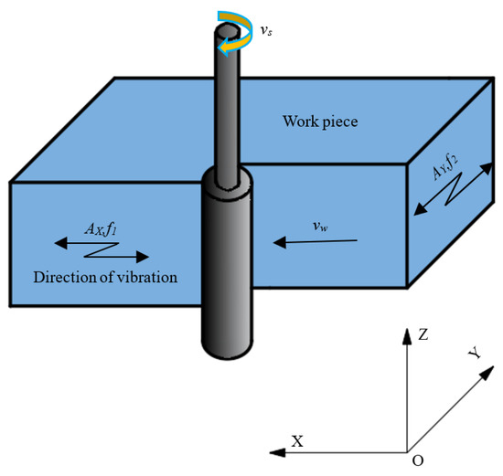
Figure 1.
Diagram of TUVAG.
(1) Ultrasonic amplitude and ultrasonic frequency remain unchanged during grinding.
(2) The shape of the abrasives is similar to that of the Vickers indenter, the size is the same, the abrasives are evenly distributed on the grinding tool, and the abrasives will not detach from the grinding tool during grinding.
(3) The shape of the abrasives remains unchanged during grinding.
Based on the above assumptions, as shown in Figure 1, the coordinate system is fixed at the center of the grinding tool, assuming that the abrasives start to contact the workpiece at time 0, and the contact point is P. The kinematic equation of abrasives is shown in Equation (1):
where R is the radius of the grinding tool, R = 5 mm; vw is the feeding rate of the grinding tool; n is the spindle speed; AX and AY are ultrasonic amplitudes in X direction and Y direction; f1 and f2 are ultrasonic vibration frequencies in X direction and Y direction, f1 = f2 = 24,600 Hz; Φ1 and Φ2 are the initial phases of tangential ultrasonic vibration and radial ultrasonic vibration. It is proved that when the phase difference between two vibration directions is 90°, the effect of vibration combination is the best, and it is a standard elliptical trajectory. Therefore, here Φ1 = 0° and Φ2 = 90°.
The velocity of abrasives during grinding can be obtained by differentiating Equation (1), as shown in Equation (2):
Similarly, in conventional grinding, the kinematics and velocity equations of abrasives are shown in Equations (3) and (4):
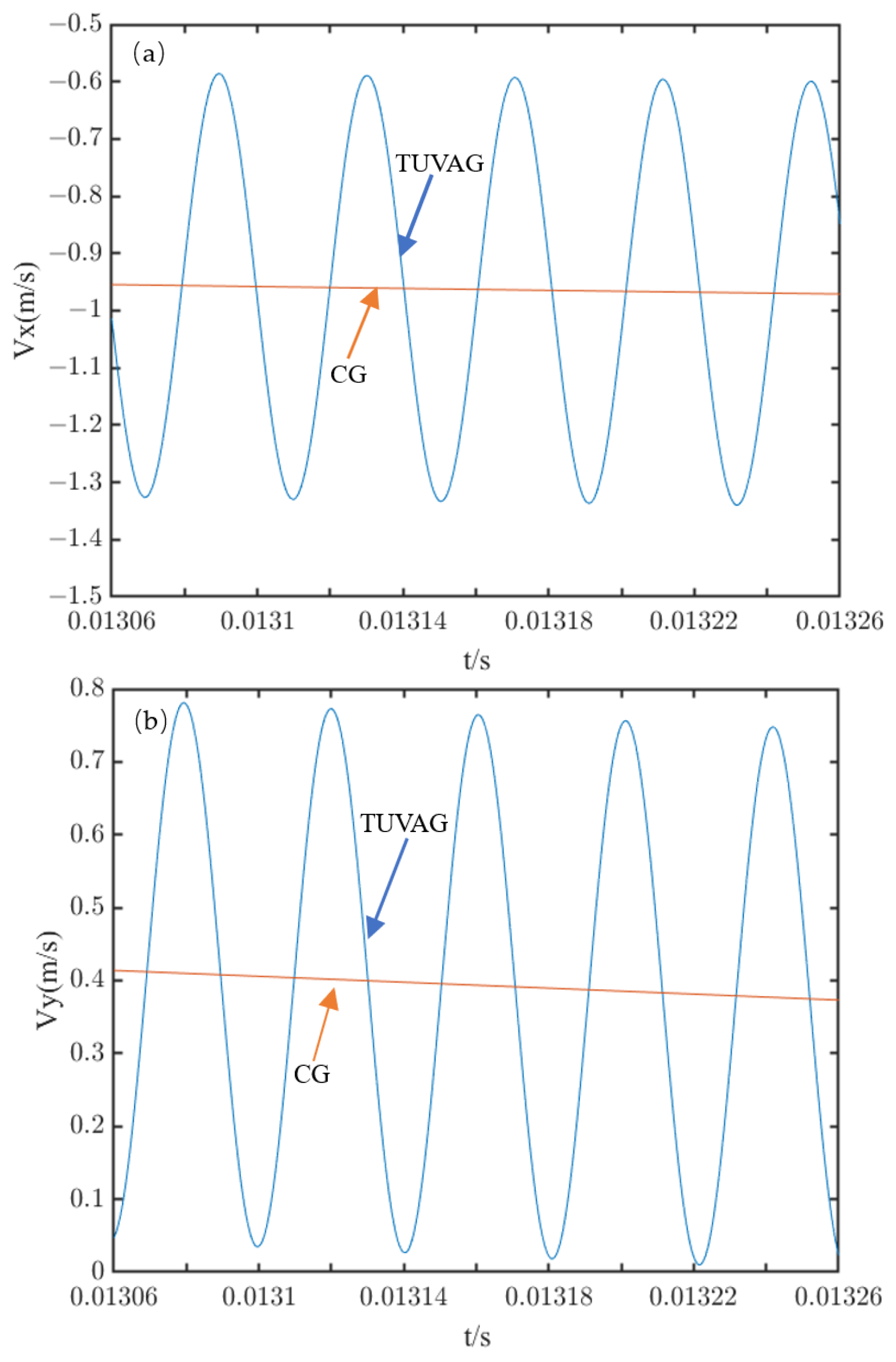
Based on Equations (1)–(4), the motion trajectory and velocity changes of abrasives during CG and TUVAG are obtained, as shown in Figure 2 and Figure 3. It can be seen from Figure 2 that the motion trajectory of a single abrasive in TUVAG is approximately elliptical in a vibration cycle. From the microscopic point of view, in a vibration cycle, the track length of abrasives in TUVAG is longer than that in CG, and under specific grinding parameters, there will be a cycle process of contact-separation-contact between abrasives and workpiece, which makes the workpiece repeatedly ground by abrasives and reduces the residual height of grinding surface. In addition, combined with Figure 3, it can be seen the grinding velocity has been changing in a large range during TUVAG, which shows that due to the existence of ultrasonic vibration, there is obvious impact in grinding, which promotes the removal of material.
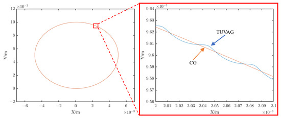
Figure 2.
Comparison of abrasive trajectory between TUVAG and CG.
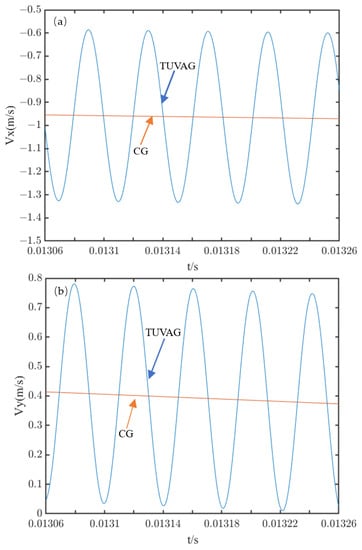
Figure 3.
Comparison of abrasive velocity between TUVAG and CG (a) X direction (b) Y direction.
3. Theoretical Model of Grinding Force in TUVAG
Grinding force, as an important index in grinding process, needs to be studied emphatically. Therefore, the grinding force prediction model of TUVAG of C/SiC composites is developed in this paper. In the process of developing the grinding force model, firstly, the grinding removal mechanism of hard and brittle material such as C/SiC composites is considered, and the models of ductile removal stage and brittle removal stage are established, respectively. Then, considering the number of active abrasives in each stage, a comprehensive grinding force prediction model including the ductile removal stage and brittle removal stage is finally given.
3.1. Grinding Removal Mechanism of C/SiC Composites
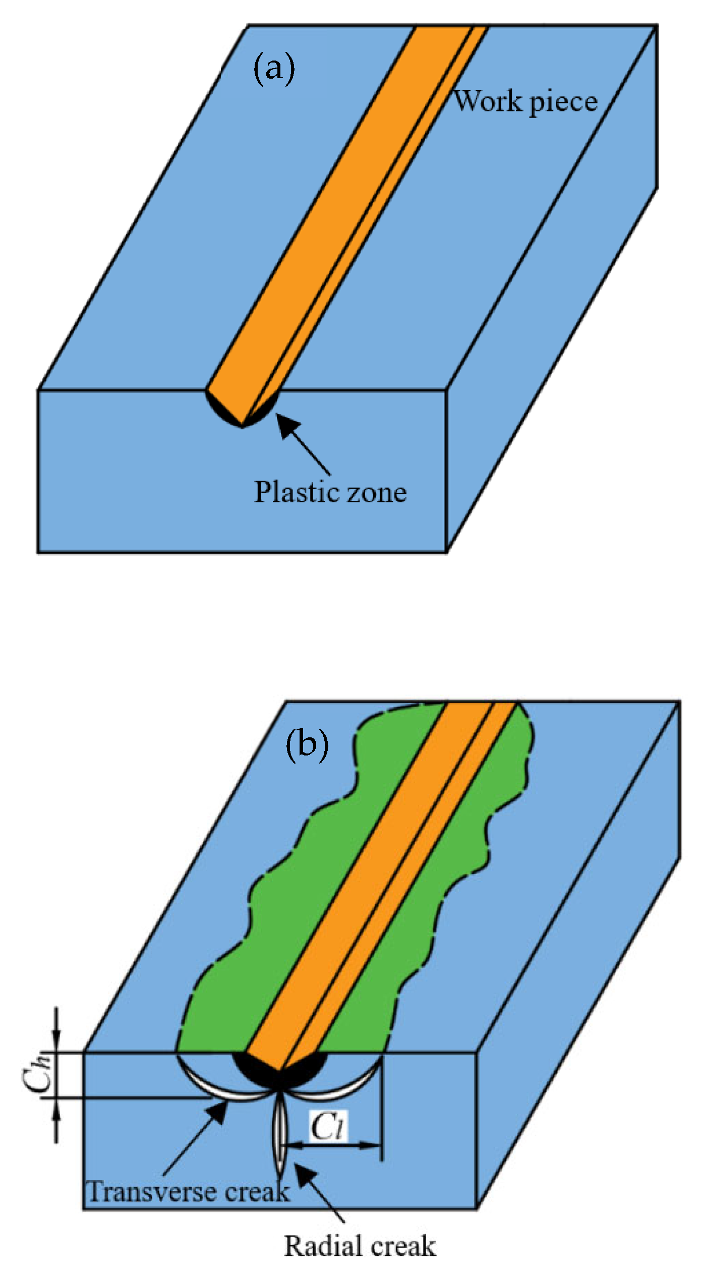
Traditionally, the removal mechanism of hard and brittle material during grinding is brittle removal. With the deepening of research, more and more scholars have found that under the specific combination of grinding parameters, hard and brittle materials such as zirconia and monocrystalline silicon will also show ductile removal characteristics. At present, the mainstream view is that in grinding hard and brittle material, the undeformed chip thickness is a process from 0 to the maximum. If the value of the maximum undeformed chip thickness (hmax) is less than the value of the critical cutting depth (agc), the ductile removal of material is dominant, otherwise, the brittle removal of material is dominant [20], as shown in Figure 4. As far as critical cutting depth (agc) is concerned, it is a value determined by the properties of material themselves. Chen et al. [21] put forward an equation for calculating the critical cutting depth of hard and brittle material, as shown in Equation (5).
where θ is the half apex angle of abrasives; KID is the dynamic toughness of hard and brittle material. For hard and brittle material, the dynamic toughness is about 30% of the static toughness, that is, KID = 0.3KIC; ξ is the geometric factor of the indenter, and the value is 1.8854 in paper [21]; λ is the comprehensive factor, and its value is (1–1.6) × 104; Hv is the Vickers hardness of the material. It has been pointed out that due to the existence of ultrasonic vibration, the surface hardness of the material decreases by about 30% [22], = 0.7Hv. The critical cutting depth of material in CG and TUVAG can be obtained in Equations (6) and (7):
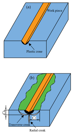
Figure 4.
Removal model of hard and brittle material (a) Ductile removal model (b) Brittle removal model.
Comparing Equations (6) and (7), it can be concluded that the critical cutting depth in TUVAG is larger than that in CG due to the weakening effect of ultrasonic vibration on surface hardness. Under the same combination of machining parameters, the ductile removal of material can be easily realized during TUVAG.
According to the existing research results, the maximum undeformed cutting thickness during CG can be obtained in Equation (8) [23,24,25]:
where C is the number of active abrasives per unit area; vw is the feeding rate; vs is the grinding velocity; ap is the grinding depth.
To calculate the chip volume conveniently, the chip is treated as a triangular pyramid, and the material removal amount of a single abrasive during CG can be obtained in Equation (9):
Similarly, during TUVAG, the material removal amount of a single abrasive can be obtained in Equation (10):
where, lCG and lTUVAG are the cutting length of a single abrasive during CG and TUVAG, respectively, which can be obtained in Equations (11) and (12).
where t is the cutting time of a single abrasive, and the relationship between t and ap is shown in Equation (13):
In a complete grinding process of abrasives, the time t used is extremely short. It can be considered that t tends to 0, then 1 − cos(2πnt) ≈ (2πnt)2/2. According to Equation (13), the time used for a complete grinding of abrasives is as shown in Equation (14):
From a macro point of view, the final material removal volume of the two processing methods is the same, then VCG = VTUVAG, the calculation formula of the maximum undeformed chip thickness of TUVAG can be obtained in Equation (15),
By comparing Equations (6)–(8) and (15), it can be concluded that the TUVAG can increase the critical cutting depth of material and reduce the maximum undeformed chip thickness, thus making it easier to realize ductile removal of C/SiC composites.
3.2. Theoretical Model of Grinding Force in Ductile Removal Stage
As shown in Figure 5, when hmax < agc, according to the analysis of Section 3.1, the material is in a ductile removal state, and the removal of the material mainly depends on the extrusion and shear between the abrasives and the workpiece, and micro-cracks rarely occur. Referring to the removal mechanism of ductile materials, the removal volume and chip shape is determined by the maximum undeformed chip thickness and the shape of abrasives. As shown in Figure 6, the abrasive is approximately treated as a Vickers indenter. According to the definition of Vickers hardness, the relationship between the instantaneous normal grinding force of a single abrasive and the cutting depth can be obtained in Equation (16):
where h is the instantaneous chip thickness of a single abrasive during grinding.
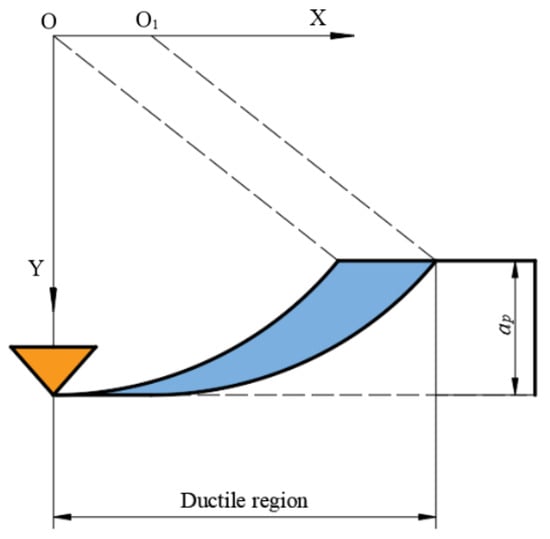
Figure 5.
Diagram of chips at the ductile removal stage.
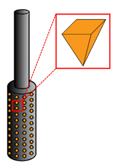
Figure 6.
Diagram of grinding tool and abrasive.
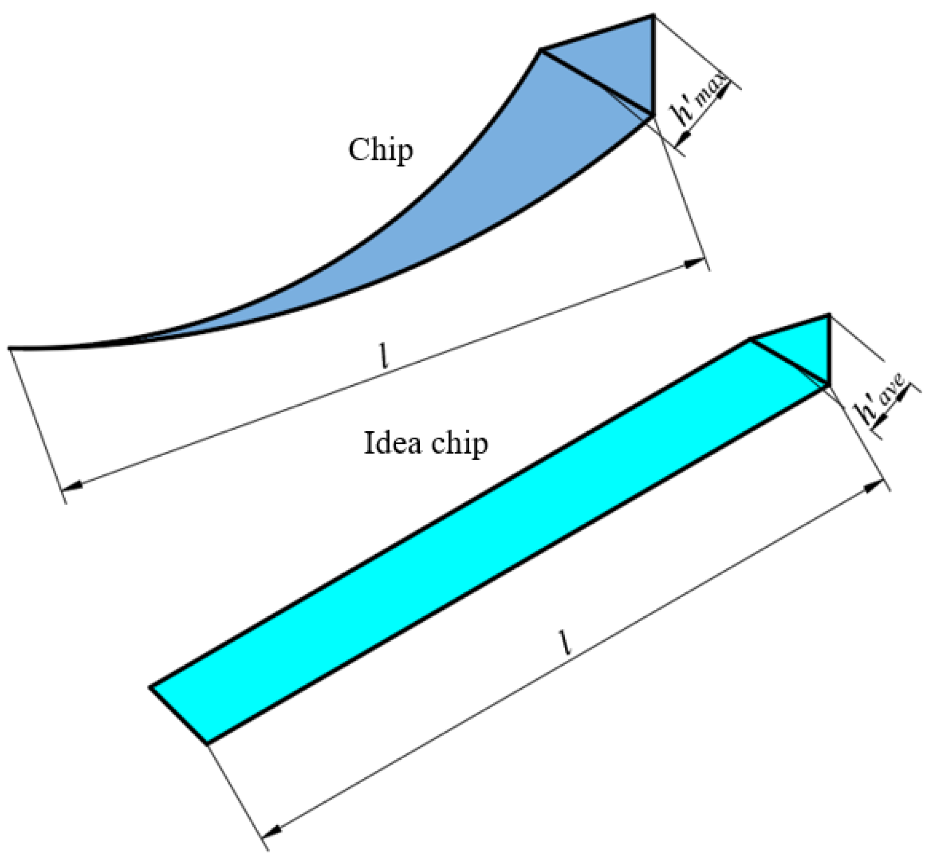
For Equation (16), since the grinding depth h changes with the cutting time, the normal grinding force fnd also changes at any time. To obtain the average normal grinding force in the whole ductile removal stage, the average cutting depth of the abrasive during grinding should be obtained. As shown in Figure 7, Xiao et al. [19], to obtain the average cutting depth of abrasives in the ductile removal stage, adopted the equivalent removal volume, that is, the triangular chip is equivalent to the triangular chip so that the removal volume of the two is equal. Based on this idea, the relationship between the average cutting depth and maximum cutting depth of abrasive was solved, as shown in Equation (17):

Figure 7.
Idealized treatment of chip.
Equation (17) is substituted into Equation (16). When the material is in the condition of ductile removal, the normal grinding force of TUVAG of a single abrasive can be obtained in Equation (18):
Considering the total number of abrasives N in the contact area between the grinding tool and the workpiece, the average normal grinding force in the ductile removal stage can be obtained in Equation (19):
For the value of N, refer to the calculation method proposed by Wang 26:
where Ca is the abrasive concentration, Ca = 100%
3.3. Theoretical Model of Grinding Force in Brittle Removal Stage
As shown in Figure 8, when h′max > agc, the material will undergo a process of ductile removal followed by brittle removal. Given that the normal grinding force at the ductile removal stage is given in Section 3.2, only the normal grinding force at the complete brittle stage are discussed here. With the grinding process, the contact stress between the workpiece and the abrasive gradually increases. According to the fracture mechanics, two main crack systems will be generated inside the material at this time: the radial crack system and the transverse crack system, as shown in Figure 4b. The radial crack is mainly related to the subsurface damage and strength reduction of the material, while the transverse crack is mainly related to the removal of the material and the formation mechanism of the surface. According to existing research results, for Vickers indenter, the depth Ch and length Cl of a transverse crack of hard and brittle materials can be obtained in Equations (21) and (22) [22,26]:
where ξ1 and ξ2 are the geometrical factors of the indenter. In fact, due to the existence of the fiber toughening phase, when the micro-cracks propagate in the material and reach the joint surface between the matrix and the fiber, the crack propagation will be temporarily prevented, and the micro-crack propagates again and deflects with the increasing grinding force, which makes the actual size of the micro-crack different from the theoretical size, and the actual calculation is extremely difficult because of the randomness of the micro-crack propagation. We assume that K1 and K2 are proportional coefficients, representing the impact of the fiber toughening phase on microcrack propagation. For C/SiC composites, Equations (21) and (22) can be modified as follows:
where, fnb is the normal grinding force of a single abrasive in the complete brittle removal stage, and and KID are the surface hardness and fracture toughness of materials when there are ultrasonic vibration effects.
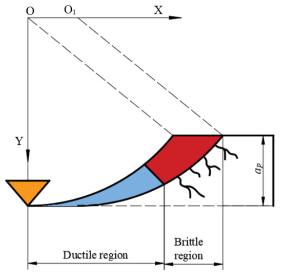
Figure 8.
Diagram of chips at the brittle removal stage.
The removal volume of a single abrasive can be obtained in Equation (25)
From the microscopic perspective, the material removal rate (MMR) can be obtained in Equation (26):
From the macro perspective, MMR can be obtained in Equation (27):
where, b is the width of the grinding area. In theory, the values of Equations (26) and (27) should be equal. Equations (23)–(25) should be substituted into Equation (26) and made equal to Equations (26) and (27). The normal grinding force of a single abrasive in the complete brittle removal stage can be obtained in Equation (28).
Since ξ1, ξ2, K1, K2 are constants related to indenter geometric parameters and material properties, in order to simplify the equation, let K = ξ1ξ2K1K2; Equation (28) can be simplified as:
In this stage, the average normal grinding force can be obtained in Equation (30):
where, Nb is the number of active abrasives in the brittle removal stage during grinding. Since it is assumed that the size and shape of abrasives are consistent and uniformly distributed on the grinding tool, the active abrasive number Nd involved in ductile region and the active abrasive number Nb involved in the brittle region can be obtained in Equations (31) and (32):
In Section 3.2, we have obtained the average grinding force in the ductile removal stage, combined with the average grinding force in the complete brittle stage and the number of active abrasives in each stage obtained in Section 3.3, we have obtained the calculation equation of the average grinding force in the whole brittle removal process.
3.4. Theoretical Model of Comprehensive Grinding Force
The removal mechanism of materials, the average normal grinding force at the ductile removal stage and the average normal grinding force at the brittle removal stage have been studied above. Therefore, by synthesizing the above, the grinding force model of TUVAG of C/SiC composites was obtained, as shown in Equation (34):
During the grinding process, normal grinding force and tangential grinding force have a linear relationship:
where, μ is friction coefficient.
4. Experiment Equipment and Condition
4.1. Experiment Equipment
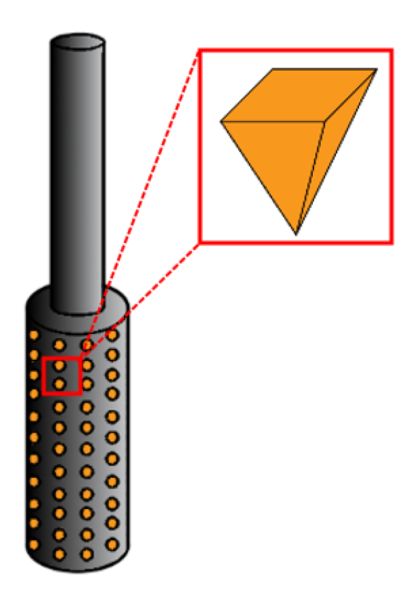
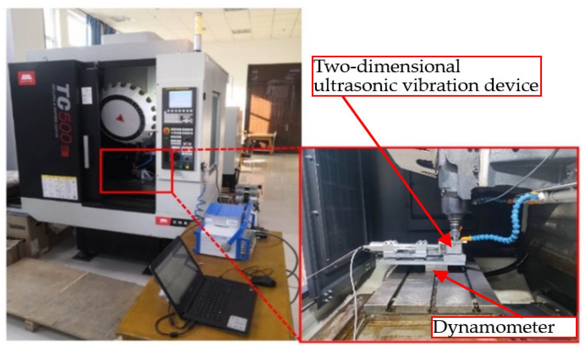
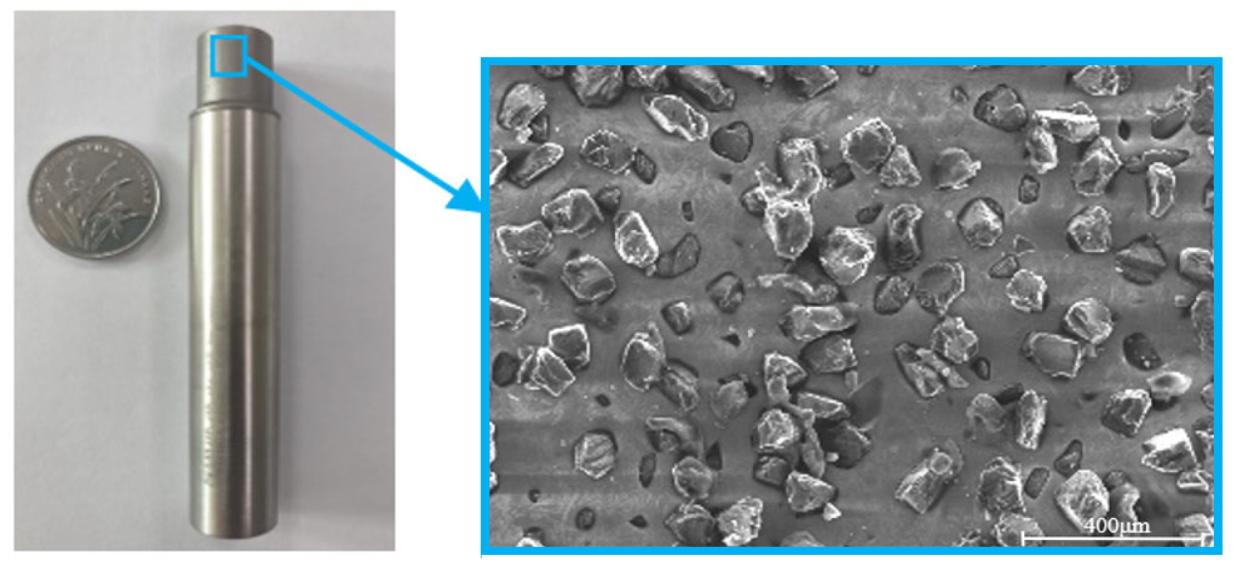
The grinding machine is TC500R high-precision vertical machining center, the maximum spindle speed is 20,000 r/min, the two-dimensional ultrasonic vibration device is fixed below the fixture, the frequency chosen in the test is 24,600 Hz, and the vibration direction is tangential and radial, as shown in Figure 9 and Figure 10. The grinding tool used in the test is single layer electroplated diamond grinding tool with a diameter of 10 mm, and an abrasive size of 200 #, as shown in Figure 11. The dynamometer is Kistler 9257 dynamometer, and the sampling frequency is 7000 Hz. The cutting force is collected by Kistler 9257 dynamometer and processed by Dynoware software to obtain the average grinding force in the grinding process, as shown in Figure 9 and Figure 10.

Figure 9.
Experiment equipment.
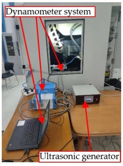
Figure 10.
Kistler 9257 Dynamometer.
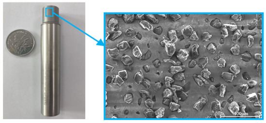
Figure 11.
Micro morphology of grinding tool.
4.2. Experiment Material and Scheme
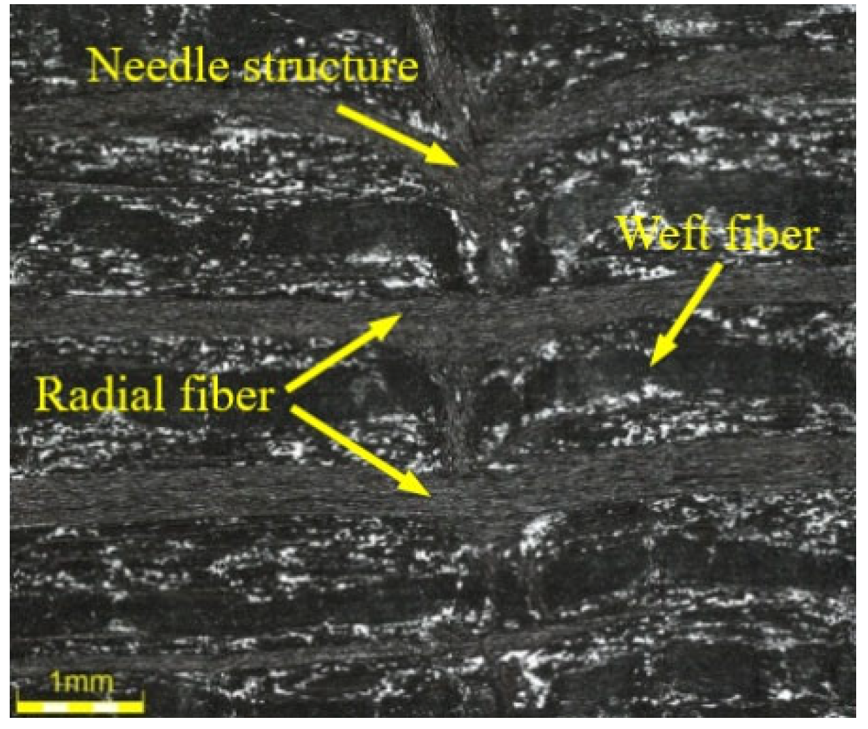
In this experiment, the experimental material used is 2.5D-C/SiC composite material, the size of 8 mm × 10 mm, the mechanical properties of 2.5D-C/SiC composite are shown in Table 1. The fiber structure composition is shown in Figure 12, including radial fibers, weft fibers, and a needle punched structure perpendicular to these two fibers.

Table 1.
Mechanical properties of the 2.5D-C/SiC composite.
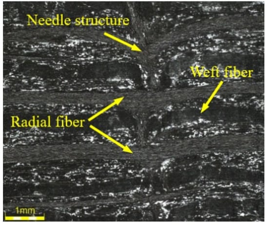
Figure 12.
Micromorphology of 2.5D-C/SiC composite.
As shown in Table 2, to verify the correctness of the grinding force model of TUVAG and analyze the impact of grinding parameters (grinding velocity vs, feeding rate vw and grinding depth ap) and ultrasonic parameters (ultrasonic amplitude A) on grinding force, the single factor experiment was carried out. To facilitate the analysis of experiment data, the ultrasonic amplitude was adjusted to make it consistent in the X and Y directions, therefore, the ultrasonic amplitude values in the two directions are no longer listed in Table 2. At the same time, the contrast experiment was carried out as the control to analyze the difference between CG and TUVAG. In the contrast experiment, the grinding parameters were consistent with in the single factor experiment, but the ultrasonic amplitude was set to 0. Therefore, the tables of the contrast experiment scheme were not listed in this paper.
Table 2.
Single factor experiment scheme.
5. Experimental Result and Discussion
5.1. Obtaining the Proportional Coefficient K
In the above section, K = ξ1ξ2K1K2. Here, the value of K was discussed.
Lawn et al. [27] obtained the calculation equations of microcrack size for hard and brittle material through research. Wang et al. [26] idealized the abrasives according to the Vickers indenter, and finally obtained the microcrack calculation equations of Equations (21) and (22). ξ1, ξ2 as the geometric factor of indenter, the specific value is only related to the shape of the abrasive, and when the shape of the abrasive is determined, ξ1, ξ2 are a fixed value. In the above hypothesis, K1 and K2 are proportional coefficients, indicating the impact of the presence of the fiber toughening phase on microcrack propagation. Theoretically, their values are only related to the structure of 2.5D-C/SiC composites.
Therefore, in this test, the above four proportional coefficients are all definite values, so the proportional coefficient K should also be a definite value. To obtain the value of K, the critical cutting depth of CG and TUVAG was obtained according to Equations (6) and (7), and the maximum undeformed chip thickness corresponding to each machining parameters combination was obtained according to Equations (8) and (15), from which the machining parameters combination under brittle removal was selected to obtain the grinding force at this time. Multiple groups of related grinding parameters are substituted into Equation (33) to obtain the value of K, which is about 1.80 in this test.
5.2. Obtaining the Friction Coefficient μ
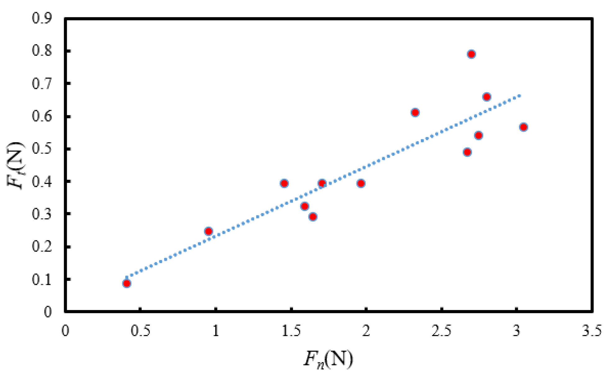
Theoretically, tangential grinding force and normal grinding force should have a linear relationship. Therefore, the single factor test results fitting was carried out, as shown in Figure 13. Then, the friction coefficient μ is about 0.221, and the tangential force can be expressed as:
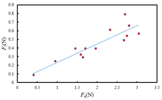
Figure 13.
Experiment value and fitting value for tangential grinding force.
5.3. Impact of Machining Parameters on Grinding Force
5.3.1. Impact of Grinding Velocity on Grinding Force
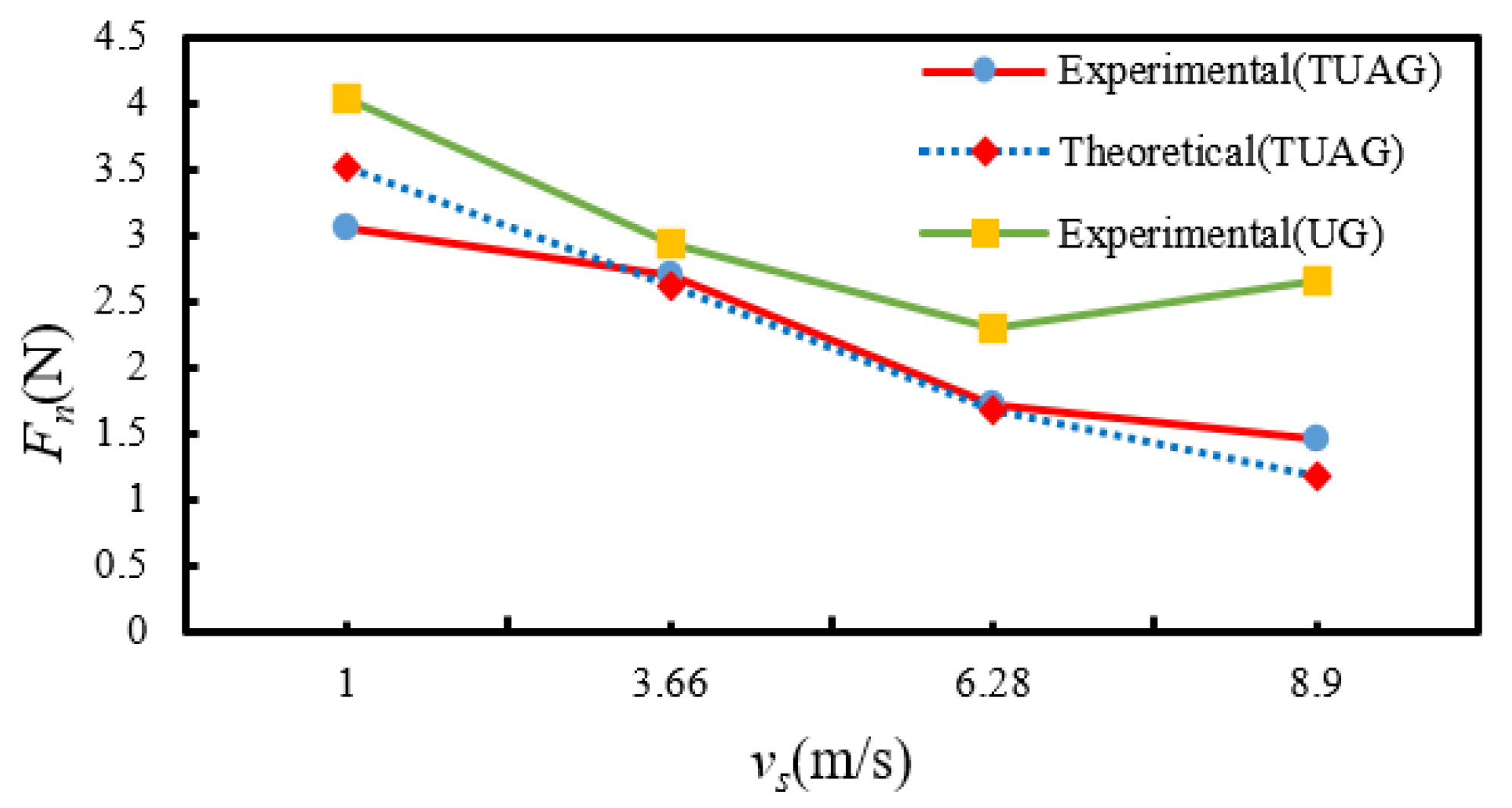
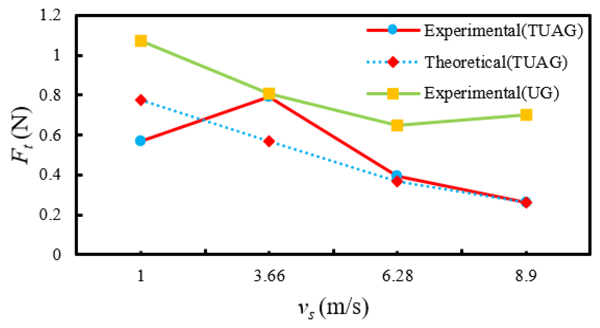
The impact of grinding velocity on normal grinding force and tangential grinding force is shown in Figure 14 and Figure 15. As can be concluded from these figures, when the grinding velocity increases from 1.00 m/s (n = 2000 r/min) to 8.90 m/s (n = 17,000 r/min), the normal and tangential grinding force in TUVAG and CG have an overall downward trend. The grinding force of TUVAG is smaller than that of CG. This situation is analyzed.

Figure 14.
Impact of grinding velocity on the normal grinding force.

Figure 15.
Impact of grinding velocity on the tangential grinding force.
When the feeding rate and grinding depth are constant, according to the above analysis, with the increase of grinding velocity, the maximum undeformed chip thickness of a single abrasive decrease. At the same time, during the cutting process, the cutting length of a single abrasive increases. According to Equation (20), the number of effective abrasives in the contact area between the workpiece and the grinding tool increases, which means that the material removal volume of abrasives decrease and the chip thickness of abrasives decrease. In addition, the increase in grinding velocity also means that the cutting time t of single abrasive decreases, which reduces the impact force of the abrasive on the workpiece, improves the chip removal conditions between the workpiece and the abrasive, slows down the wear of the abrasive, and better maintains the good cutting conditions. However, by comparing Figure 13 and Figure 14, it can be seen that during CG, when the grinding velocity is 8.90 m/s, the tangential grinding force and normal grinding force will show an upward trend, which is speculated to be because the spindle speed is 17,000 r/min. It is close to the limit speed of the machine tool spindle (the limit speed is 20,000 r/min). In addition, the radial runout of the machine tool spindle, the vibration of the machine tool itself and other factors lead to the increase in grinding force.
5.3.2. Impact of Feeding Rate on Grinding Force
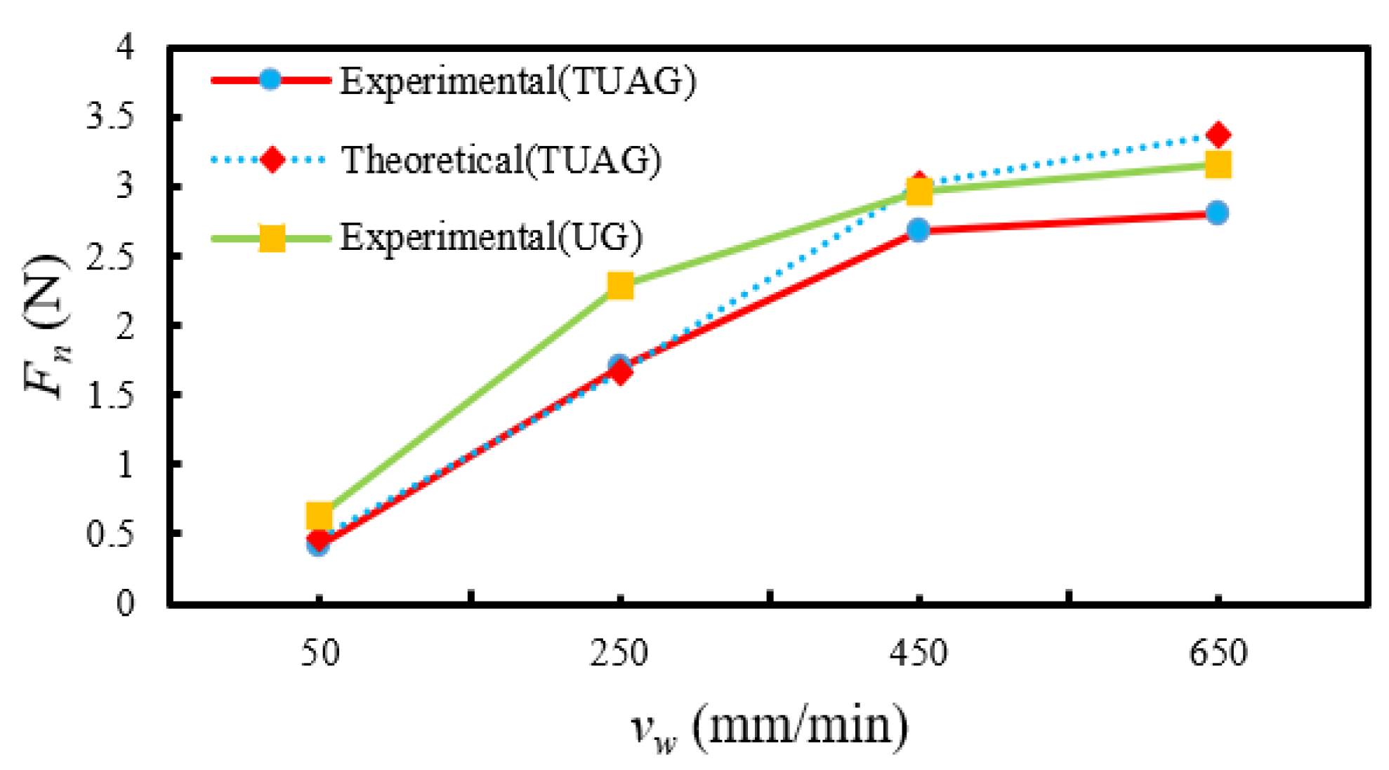
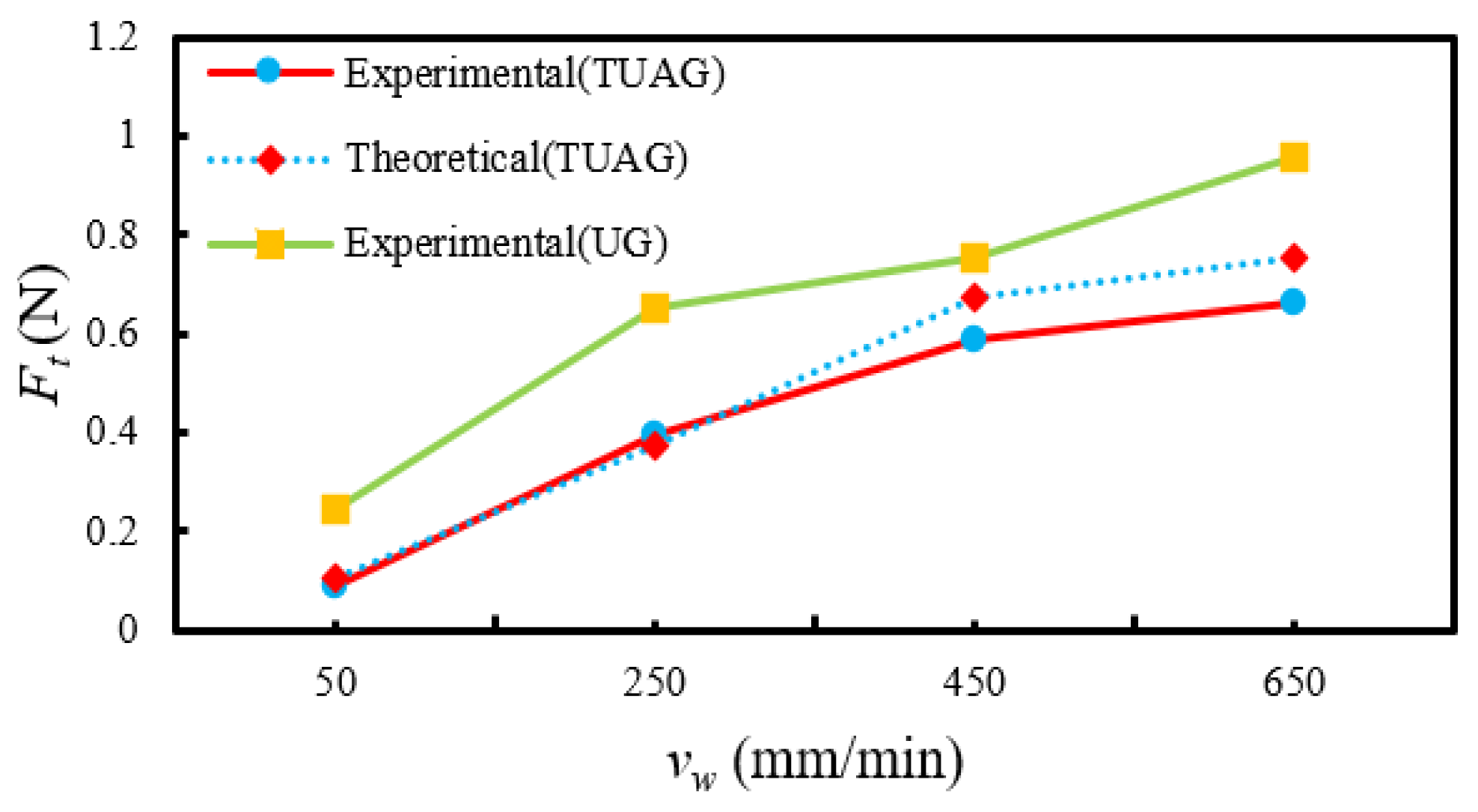
The impact of the feeding rate on normal grinding force and tangential grinding force is shown in Figure 16 and Figure 17. It can be concluded from these figures, when the feeding rate increases from 50 mm/min to 650 mm/min, the normal and tangential grinding force in TUVAG and CG both show an upward trend, and the grinding force in TUVAG are significantly less than those in conventional grinding. This situation is analyzed.
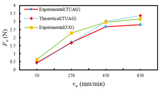
Figure 16.
Impact of feeding rate on the normal grinding force.
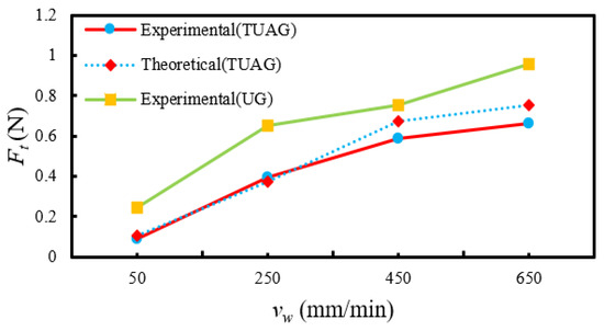
Figure 17.
Impact of feeding rate on the tangential grinding force.
When the grinding velocity and grinding depth are constant, when the feeding rate is low, according to Equation (8), the maximum undeformed chip thickness of a single abrasive is low, which means that the ductile removal mode accounts for a large proportion in the material removal process at this time, reducing the overall grinding force. At the same time, the lower feeding rate means that the number of active abrasives that can participate in the grinding per unit time is higher, the chip thickness of a single abrasive is reduced, and the chips can be more smoothly discharged with the rotation of the grinding tool, maintain good heat dissipation condition, and reduce the wear degree of abrasives. Under the impact of the above conditions, the grinding force value is lower. When the feeding rate continues to increase, the above conditions continue to deteriorate, and because the grinding chips are difficult to discharge smoothly, the gap between the grinding abrasives on the grinding tool is blocked by the chips, making it difficult for the grinding tool to maintain the normal cutting process, the grinding heat accumulation gradually, resulting in the increase in grinding force.
5.3.3. Impact of Grinding Depth on Grinding Force
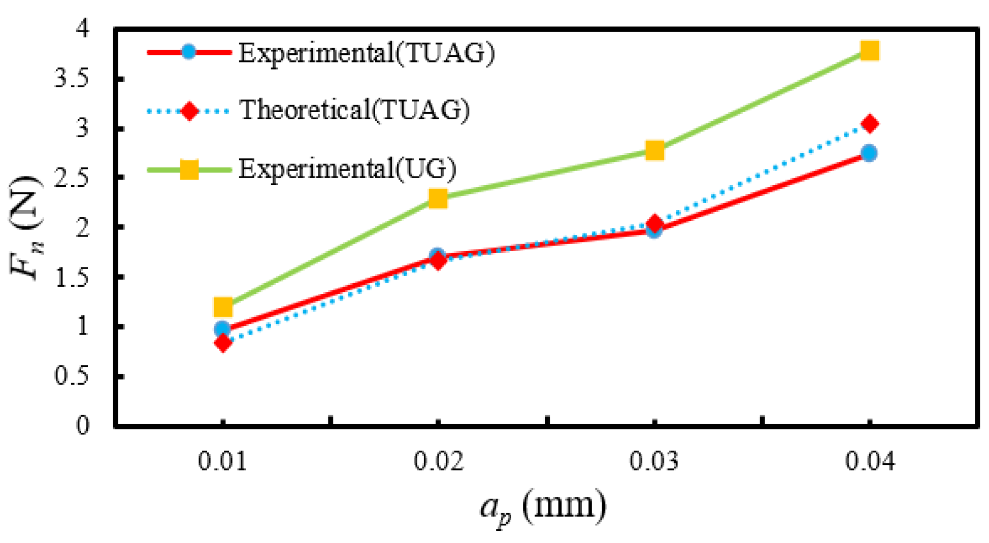
The impact of grinding depth on normal grinding force and tangential grinding force is shown in Figure 18 and Figure 19. It can be concluded from these figures that when the grinding depth increases, the normal and tangential grinding force of TUVAG and CG both show an increasing trend. This situation is analyzed.

Figure 18.
Impact of grinding depth on the normal grinding force.
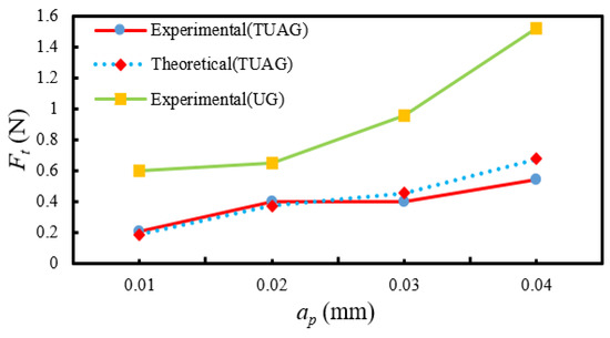
Figure 19.
Impact of grinding depth on the tangential grinding force.
It can be concluded from the above analysis that the grinding depth mainly affects the cutting time t of the abrasives, the maximum undeformed chip thickness hmax and other important parameters. Therefore, when the grinding depth is low, the cutting time t of abrasives is shorter, and the cutting heat is not easy to accumulate, and the maximum undeformed chip thickness is reduced, and the material is mainly plastic removed. At the same time, when the grinding depth is low, the microscopic separation between a single abrasive and the workpiece caused by radial vibration is more obvious, which further reduces the impact between a single abrasive and the workpiece, making the overall grinding at this time lower. With the increase in grinding depth, the cutting time t of abrasives increases and the impact of abrasives on the workpiece increases. In addition, the maximum undeformed chip thickness of a single abrasive is larger than the critical cutting depth of the workpiece. The material is dominated by brittle removal. According to Equation (34), the grinding force is proportional to the grinding depth during brittleness removal, making the grinding force increase continuously.
5.3.4. Impact of Ultrasonic Vibration on Grinding Force
By comparing Figure 14, Figure 15, Figure 16, Figure 17, Figure 18 and Figure 19, it can be concluded that the grinding force in CG is significantly higher than that in TUVAG, and it can be concluded from Figure 19 that with the increase of ultrasonic amplitude, the grinding force shows a downward trend. The impact of ultrasonic vibration and ultrasonic amplitude on the grinding force was analyzed.
It can be concluded from the above analysis that, from a microscopic point of view, the cutting length of a single abrasive in TUVAG is larger than that in CG. Under the same grinding parameter combination, the maximum undeformed chip thickness of a single abrasive in TUVAG is smaller than that in CG. Moreover, due to the weakened effect of ultrasonic vibration on the surface hardness of material, the surface hardness of material decreases and the critical cutting depth of the material increases. Therefore, under the same grinding parameter combination, it is easier to achieve the ductile removal of material during TUVAG, which not only obtains better surface quality but also reduces the grinding force during machining. In addition, due to the existence of ultrasonic vibration, there is always a small impact between the abrasive and the workpiece, the long and continuous chips into short but not continuous chips, reducing the friction coefficient between the grinding tool and the workpiece, promote the chip discharge, slow down the wear of abrasives, and further reduce the grinding force.
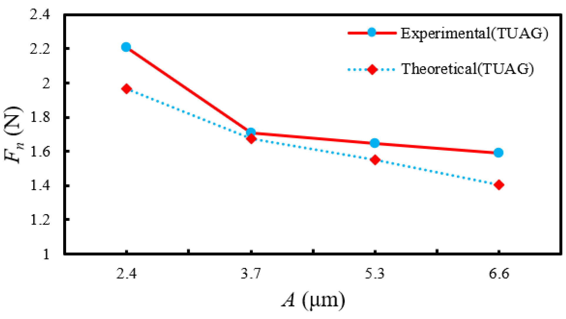
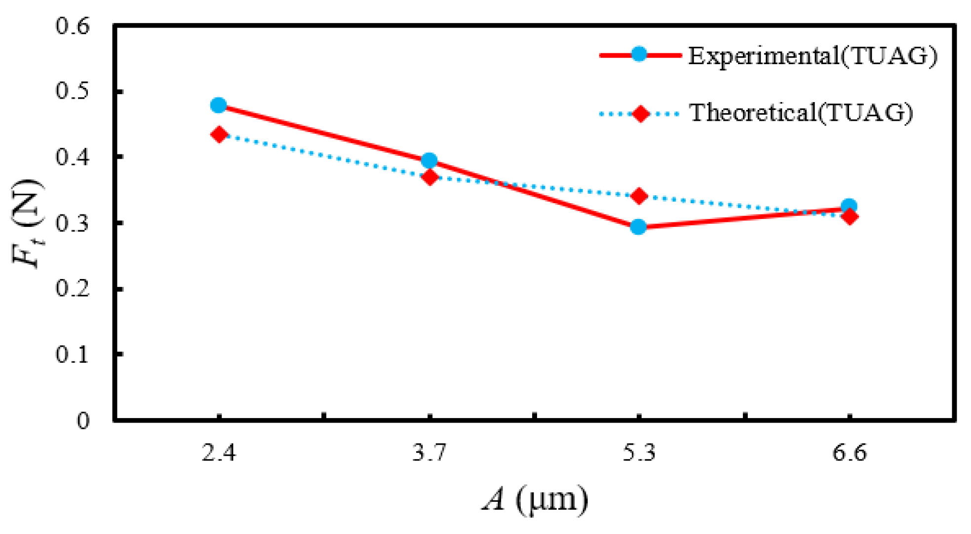
The impact of ultrasonic amplitude on grinding force is shown in Figure 20 and Figure 21. It can be concluded from these figures that with the increase of ultrasonic amplitude, normal grinding force and tangential grinding force show a downward trend overall. This is because when the ultrasonic amplitude increases, the cutting length of a single abrasive further increases, which makes the maximum undeformed chip thickness of a single abrasive decrease; the ductile removal mode accounts for a large proportion of the material removal process, and the grinding force decreases. At the same time, due to the increase in ultrasonic amplitude, the micro-impact between the abrasives and the workpiece is increased, resulting in a large amount of micro-cracks on the surface. The micro-cracks are interleaved with each other, which promotes the removal of material and further reduces the grinding force.
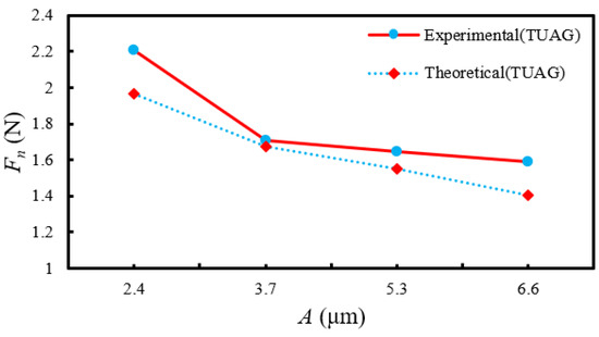
Figure 20.
Impact of ultrasonic amplitude on the normal grinding force.
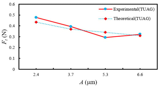
Figure 21.
Impact of ultrasonic amplitude on the tangential grinding force.
5.4. Verification of Grinding Force Model
The errors between theoretical values and measured values corresponding to different ultrasonic parameters and grinding parameters are calculated, as shown in Table 3. It can be concluded from the table that the maximum relative error of normal grinding force is 11.99%, the minimum relative error is 4.45% and the average relative error is 8.49%. The maximum relative error of tangential grinding force is 18.17%, the minimum relative error is 8.91% and the average relative error is 13.59%. It can be seen that the relative errors are all within 20%, indicating that the model has certain feasibility. At the same time, it is concluded that the error value of tangential grinding force is large, which may be because the friction coefficient μ between the grinding tool and the workpiece in TUVAG is obtained by fitting the test data. Due to the small sample size of the test data, the fitting friction coefficient μ has a certain error compared with the real friction coefficient. The relative error of the tangential grinding force is larger.
Table 3.
Relative errors between theoretical and measured values of grinding force.
6. Conclusions
Based on the maximum undeformed chip thickness of a single abrasive, the removal mechanism of 2.5D-C/SiC composites during grinding was analyzed. From the perspectives of ductile removal and brittle removal, the grinding force model of TUVAG for 2.5D C/SiC composites was developed. Through the single factor test, the impact law of ultrasonic parameters and grinding parameters on grinding force and the feasibility of grinding force model were analyzed, and the following conclusions were drawn:
(1) The relationship between the critical cutting depth and the maximum undeformed chip thickness of a single abrasive determines the material removal mechanism. If the critical cutting depth is greater than the maximum undeformed chip thickness of a single abrasive, the material removal mode is ductile removal. On the contrary, the material removal mode is mainly brittle removal.
(2) During the grinding process, when the feed rate and grinding depth increase, the grinding force increases. When the grinding velocity and ultrasonic amplitude increase, grinding force decreases.
(3) Ultrasonic vibration can reduce the surface hardness of C/SiC composites, increase the critical cutting depth, and reduce the maximum undeformed chip thickness of a single abrasive. Therefore, compared with CG, the grinding force of TUVAG decreases obviously.
(4) The grinding force calculated by the theoretical grinding force model are consistent with the experimental value. The average relative error of the normal grinding force is 8.49% and the average relative error of the tangential grinding force is 13.59%. Therefore, the model can be used to predict the grinding force of TUVAG of C/SiC composites.
Author Contributions
Formal analysis, C.T. and S.J.; funding acquisition, Y.Z.; project administration, Y.Z.; validation, G.Y.; writing—original draft, C.T.; writing—review and editing, Y.Z., L.M. and Y.G. All authors have read and agreed to the published version of the manuscript.
Funding
This research is funded by the National Natural Science Foundation of China: 51905083, 51975113; the Natural Science Foundation of Hebei Province: E2022501004, E2021501027; the Fundamental Research Funds for the Central Universities: N2123025, N2203015, and the China Postdoctoral Science Foundation: 2021MD703912.
Data Availability Statement
The data and materials that support the findings of this study are available from the corresponding author upon reasonable request.
Conflicts of Interest
The authors declare no conflict of interest.
References
- Qu, S.S.; Gong, Y.D.; Yang, Y.Y. An investigation of carbon nano fluid minimum quantity lubrication for grinding unidirectional carbon fibre-reinforced ceramic matrix composites. J. Clean. Prod. 2020, 249, 119353. [Google Scholar] [CrossRef]
- Li, C.; Piao, Y.; Meng, B.; Hu, Y.; Li, L.; Zhang, F. Phase transition and plastic deformation mechanisms induced by self-rotating grinding of GaN single crystals. Int. J. Mach. Tools Manuf. 2022, 172, 103827. [Google Scholar] [CrossRef]
- Li, C.; Piao, Y.C.; Zhang, F.H.; Zhang, Y.; Hu, Y.X.; Wang, Y.F. Understand anisotropy dependence of damage evolution and material removal during nanoscratch of MgF2 single crystals. Int. J. Extrem. Manuf. 2023, 5, 015101. [Google Scholar] [CrossRef]
- Ding, K.; Fu, Y.C.; Su, H.H. Study on surface/subsurface breakage in ultrasonic assisted grinding of C/SiC composites. Int. J. Adv. Manuf. Technol. 2017, 91, 3095–3105. [Google Scholar] [CrossRef]
- Li, Z.; Jiao, Y.; Deines, T.W.; Pei, Z.J.; Treadwell, C. Rotary ultrasonic machining of ceramic matrix composites: Feasibility study and designed experiments. Int. J. Mach. Tools Manuf. 2005, 45, 1402–1411. [Google Scholar] [CrossRef]
- Ramulu, M.; Jenkins, M.G.; Guo, Z. Abrasive water jet machining mechanisms incontinuous-fiber ceramic composites. J. Compos. Technol. Res. 2001, 23, 82–91. [Google Scholar]
- Sun, Y.; Jin, L.Y.; Gong, Y.D. Experimental evaluation of surface generation and force time-varying characteristics of curvilinear grooved micro end mills fabricated by EDM. Manuf. Process. 2022, 73, 799–814. [Google Scholar] [CrossRef]
- Li, C.; Hu, Y.X.; Zhang, F.H. Molecular dynamics simulation of laser assisted grinding of GaN crystals. Int. J. Mech. Sci. 2023, 239, 107856. [Google Scholar] [CrossRef]
- Ding, K.; Fu, Y.C.; Su, H.H. Study on Matching Performance of Ultrasonic Vibration and Grinding Parameters Based on a Single Abrasive Grinding. J. Mech. Eng. 2017, 19, 59–65. [Google Scholar] [CrossRef]
- Cao, J.G.; Nie, M.; Liu, Y.M.; Li, J.Y. Ductile-brittle transition behavior in the ultrasonic vibration-assisted internal grinding of silicon carbide ceramics. Int. J. Adv. Manuf. Technol. 2018, 96, 3251–3256. [Google Scholar] [CrossRef]
- Chen, J.; An, Q.L.; Ming, W.W.; Chen, M. Investigation on machined surface quality in ultrasonic-assisted grinding of Cf/SiC composites based on fracture mechanism of carbon fibers. Int. J. Adv. Manuf. Technol. 2020, 109, 1583–1599. [Google Scholar] [CrossRef]
- Guo, B.; Zhao, Q.L. Ultrasonic vibration assisted grinding of hard and brittle linear micro-structured surfaces. Precis. Eng. 2016, 48, 98–106. [Google Scholar] [CrossRef]
- Cao, J.G.; Wu, Y.B.; Lu, D.; Fujimoto, M.; Nomura, M. Material removal behavior in ultrasonic-assisted scratching of SiC ceramics with a single diamond tool. Int. J. Mach. Tools Manuf. 2014, 79, 49–61. [Google Scholar] [CrossRef]
- Liang, Z.Q.; Wang, X.B.; Wu, Y.B.; Xie, L.J.; Jiao, L.; Zhao, W.X. Experimental study on brittle–ductile transition in elliptical ultrasonic assisted grinding (EUAG) of monocrystal sapphire using single diamond abrasive grain. Int. J. Mach. Tools Manuf. 2013, 7, 41–51. [Google Scholar] [CrossRef]
- Yan, Y.Y.; Zhang, Z.Q.; Zhao, B.; Liu, J.L. Study on prediction of three-dimensional surface roughness of nano-ZrO2 ceramics under two-dimensional ultrasonic-assisted grinding. Int. J. Adv. Manuf. Technol. 2021, 112, 2623–2638. [Google Scholar] [CrossRef]
- Sun, G.Y.; Zhao, L.L.; Ma, Z.; Zhao, Q.L. Force prediction model considering material removal mechanism for axial ultrasonic vibration-assisted peripheral grinding of Zerodur. Int. J. Adv. Manuf. Technol. 2018, 98, 2775–2789. [Google Scholar] [CrossRef]
- Yang, Z.C.; Zhu, L.D.; Lin, B.; Zhang, G.X.; Ni, C.B.; Sui, T.Y. The grinding force modeling and experimental study of ZrO2 ceramic materials in ultrasonic vibration assisted grinding. Int. J. Mech. Sci. 2019, 45, 8873–8889. [Google Scholar] [CrossRef]
- Li, C.; Zhang, F.H.; Meng, B.B. Material removal mechanism and grinding force modelling of ultrasonic vibration assisted grinding for SiC ceramics. Ceram. Int. 2017, 43, 2981–2993. [Google Scholar] [CrossRef]
- Xiao, X.Z.; Zheng, K.; Liao, W.H.; Meng, H. Study on cutting force model in ultrasonic vibration assisted side grinding of zirconia ceramics. Int. J. Mach. Tools Manuf. 2016, 104, 58–67. [Google Scholar] [CrossRef]
- Cheng, J.; Gong, Y.D. Experimental study of surface generation and force modeling in micro-grinding of single crystal silicon considering crystallographic effects. Int. J. Mach. Tools Manuf. 2014, 77, 1–15. [Google Scholar] [CrossRef]
- Chen, M.J.; Zhao, Q.L.; Dong, S.; Li, D. The critical conditions of brittle–ductile transition and the factors influencing the surface quality of brittle materials in ultra-precision grinding. J. Mater. Process. Technol. 2005, 168, 75–82. [Google Scholar] [CrossRef]
- Wang, Y.; Lin, B.; Wang, S.L.; Cao, X.Y. Study on the system matching of ultrasonic vibration assisted grinding for hard and brittle materials processing. Int. J. Mach. Tools Manuf. 2014, 77, 66–73. [Google Scholar] [CrossRef]
- Dai, C.W.; Ding, W.F.; Zhu, Y.J.; Xu, J.H.; Yu, H.W. Grinding temperature and power consumption in high speed grinding of Inconel 718 nickel-based superalloy with a vitrified CBN wheel. Precis. Eng. 2018, 52, 192–200. [Google Scholar] [CrossRef]
- Mao, C.; Liang, C.; Zhang, Y.C.; Zhang, M.J.; Hu, Y.L.; Bi, Z.M. Grinding characteristics of cBN-WC-10Co composites. Ceram. Int. 2017, 43, 16539–16547. [Google Scholar] [CrossRef]
- Zhang, X.H.; Kang, Z.X.; Li, S.; Shi, Z.Y.; Wen, D.D.; Jiang, J.; Zhang, Z.C. Grinding force modelling for ductile-brittle transition in laser macro-micro-structured grinding of zirconia ceramics. Ceram. Int. 2019, 45, 18487–18500. [Google Scholar] [CrossRef]
- Wang, S.F. Research on Grinding Mechanism of Elliptical Ultrasonic Assisted Diamond Grinding Wheel for K9 Glass; Northeastern University: Shenyang, China, 2021. [Google Scholar]
- Marshall, D.; Lawn, B.; Evans, A. Elastic/plastic indentation damage in ceramics:the lateral crack system. J. Am. Ceram. Soc. 1982, 65, 561–566. [Google Scholar] [CrossRef]


Disclaimer/Publisher’s Note: The statements, opinions and data contained in all publications are solely those of the individual author(s) and contributor(s) and not of MDPI and/or the editor(s). MDPI and/or the editor(s) disclaim responsibility for any injury to people or property resulting from any ideas, methods, instructions or products referred to in the content. |
© 2023 by the authors. Licensee MDPI, Basel, Switzerland. This article is an open access article distributed under the terms and conditions of the Creative Commons Attribution (CC BY) license (https://creativecommons.org/licenses/by/4.0/).