Abstract
Chiral nematic liquid crystals (CLCs), with a unique helix structure, have attracted immense recognition over the last few decades owing to the abundant presence in natural phenomena and their diverse applications. However, the optical properties of CLC are usually hindered by the abundance of the so-called fingerprint domains. Up to now, studies have worked on controlling the in-plane orientation of the lying helix through surface rubbing and external stimuli. It remains challenging to achieve a steady and uniform lying helical structure. Here, by varying the surface anchoring strength, a uniform lying helical structure with long-range order is achieved as thermodynamically stable state without any external support. Poly (6-(4-methoxy-azobenzene-4’-oxy) hexyl methacrylate) (PMMAZO)—a liquid crystalline polymer—is deposited onto the silicon substrate to fine-tune the surface anchoring. By changing the grafting density of PMMAZO, both pitch size and morphology of the lying helical structure can be controlled. As the grafting density increases, the enhanced titled deformation of helical structure suppresses the pitch size of CLC at the same cell thickness; as the cell thickness increases, the morphology transition from long-range order stripes to small fingerprint domains is facilitated.
1. Introduction
The impressive set of properties displayed by naturally occurring helical superstructure in living organisms are omnipresent. These supramolecular helical structures exhibit sophisticated phenomena such as iridescence [1], camouflage [2], and mechanical stability [3] are some to mention. The morphological and optical characteristics of biopolymers have been studied to corelate their existence with the cholesteric organization established [4]. Biomimicry of such structural characteristics has the potential to create low cost self-assembled sensors [5], smart windows [6], and many more compelling applications [7]. The self-organized molecular arrangement of helix structure in cholesteric liquid crystals (CLCs) bears resemblance to these helical superstructures witnessed in nature. The CLC system has been studied to interpret these properties that are dependent on morphology and orientation as a step towards biomimetics in materials science [4,5,6,8,9]. The cholesteric phase can be induced via the addition of a chiral dopant in the nematic phase of LCs. These additions alter the directional order described by the director n(r), which is uniform in the nematic phase but adopts a helical twisting in the cholesteric one [10]. The ability of the chiral dopant to induce a helical twisting of director n is known as the helical twisting power (HTP). The HTP can control the pitch of CLC i.e., the distance covered when the director completes a rotation of 360° from its initial position. External stimuli such as electric fields can also alter the pitch of CLCs. The pitch of the CLC has a magnitude and a sign due to the left- or right-handed assembly of molecules.
The confined CLC usually adopts three different textures owing to the different orientation of helical axis [11]: The Grandjean structure or uniform standing helix where the helix axis is perpendicular to the substrate; the fingerprint domains where the helix axis is parallel to the surface; and a random texture where the axis does not have any particular direction with respect to the substrate. For the lying down helix (fingerprint structure), when the helix axis is oriented in a single direction thereby resulting in a structure displaying periodic stripe patterns, defines the uniform lying helix (ULH). The discovery of flexoelectric-optic effect [12] inherent to the short pitch ULH brought it into the spotlight considering the favourable features like response time, viewing angle, and contrast. Other significant application areas include beam steering [13], display technologies [14], and many more. Despite such a wide area of application, to obtain a ULH with good stability and quality still remains challenging, since the Grandjean structure is a thermodynamically stable state while ULH or the long-range ordered lying down helix is a metastable one. To overcome these obstacles, numerous techniques have been employed with and without application of electric field.
Previous work on stabilizing the ULH structure employed external stimuli such as electric fields [15], magnetic fields [16], and light irradiation [17] to control the orientation of the helical axis. Zheng et al. reported irradiation of UV light on CLCs to facilitate the ULH formation through morphology transition via exposure time [17]. With increasing exposure, the helix structure unwound and was then assembled into standing helix followed by periodic stripes. This 3D manipulation of axis was utilised for 2D beams steering application. The principle behind ULH stabilization via external stimuli is providing initial energy to the system so that the metastable stage becomes thermodynamically stable. Some works incorporated polymers in the system to stabilize the structure [18,19,20]. Rudquist et al. photopolymerized bulk sample establishing a polymer network so as to maintain the ULH structure [20]. The resulting polymer network was found to be robust and the structure of ULH remains stable even after removal of the electric field. Carborane et al. built periodic microchannels of polymer so that the confined ULH texture has lower free energy as compared to the Grandjean one [19]. Park et al. executed a study on the surface pretilt angle and anchoring energy on the alignment of ULH [21]. A stacked vertical alignment material diluted with solvent coated on a planar surface to modify the pretilt angle was employed, and reactive mesogen was introduced in the system to control the anchoring energy. It was discovered that the surface with weak anchoring energy and a high pretilt angle is prone to the formation of ULH over the other conditions. Other surface treatments used to obtain the stable lying down helix consisted of periodic surface anchoring designed by photolithography [22], micro grooves formed on surface with weak homeotropic anchoring [23], periodic surface structures [24], and micro-channels [25].
In this work, we propose to study how the anchoring energy induces changes in the morphology of CLCs confined in hybrid cells. This was achieved by varying the cell thickness and the grafting density of polymer brushes on the bottom substrate. The comprehensive understanding of system is quintessential in order to use the surface anchoring as a force to guide the helical axis orientation of chiral nematic structures. The morphology transition and precise dimension control of thermodynamically stabilized CLCs based on varying the density of polymer brushes is yet to be investigated. In previous work, the grafting densities acquired via varying concentration of Poly (6-(4-methoxy-azobenzene-4’-oxy) hexyl methacrylate) PMMAZO solution on a clean Si substrate were tuned to provide anchoring from planar to perpendicular for nematic LCs [26]. The out-of-plane tilt angle was modulated effectively for nematic liquid crystal 5CB and can be changed gradually from perpendicular to planar. It has been proven that the highly dense brush results in planar alignment whereas the low-density brush caused the chain to extend in the narrow region around the surface thereby providing homeotropic alignment. However, the alignment control and stabilization of CLCs is more challenging than nematic LCs due to the similar energy states between different helical configurations (e.g., fingerprint and Grandjean); which often requires external fields to maintain the target morphology as an equilibrium state. Here, CLCs were confined in two groups of cells, homeotropic cells and hybrid cells. In homeotropic cells, both surfaces were treated with octadecyl-trichlorosilane (OTS), and strong homeotropic anchoring was obtained. Hybrid cells had the top surfaces modified by OTS, and the bottom surfaces were spin-coated with different concentrations of PMMAZO. For different cell dimensions, a long-range ordered lying down helix or striped patterns and fingerprints were observed in different cells. The two morphologies did not repel each other, but rather showed a transitional relationship that varied with the thicknesses and grafting densities of the cells.
2. Results and Discussion
The investigation and characterization of morphology and dimension variation are accomplished through a number of CLC cells, in which the CLCs are confined between silicon (Si)-substrate and octadecyl trichlorosilane (OTS)-modified transparent glass slides with different cell thicknesses. The bottom Si-substrates are either treated with OTS to get a cell with homeotropic anchoring on both surfaces, or modified with the hydroxyl-terminated PMMAZO [26] to create a hybrid cell. In the hybrid anchoring cell, the PMMAZO modified surfaces have the ability to gradually change the surface anchoring from weak homeotropic [27] to titled planar anchoring by varying the PMMAZO brush grafting density. It has been demonstrated in our previous work that in a nematic liquid crystal 5CB system, 5CB molecules act as a good solvent to PMMAZO polymer brush [28]. The chain conformations of the PMMAZO brush in 5CB are altered according to the grafting density of brush layer: High grafting density of the polymer backbone extending away from substrate causes side-chain mesogens parallel to the substrate to induce planar anchoring; low grafting density of the polymer backbone lying on the surface results in the mesogens being perpendicular to the substrate to induce homeotropic anchoring; the grafting density in between produces different tilt angles of 5CB. In a chiral nematic system, the distinct organization of helix structure will be examined based on the surface anchoring and cell thickness change through polarized optical microscopy observation.
Different concentrations of PMMAZO solutions are used to finely tune the brush layer thickness, in order to achieve the gradual change of grafting density of the polymer brush. A series of ~2 to ~4 nm thick films of PMMAZO are coated onto cleaned Si substrates, and then subjected to 250 °C thermal annealing and subsequence sonication in the same solvent, chlorobenzene, to remove unbonded polymers. The grafting density is computed according to the equation [26]
where h is the film thickness, ρ is the density is 1.25 g/mL for PMMAZO, NA is Avogadro’s number, 10−21 is a conversion factor, and Mn is the molecular weight used in this work is 110K. As shown in Table 1, by increasing the film thickness, the grafting density increases for 1.72 to 3.18 chains/nm2, representing the enlargement of the number of polymer chains per unit area.

Table 1.
Thicknesses and grafting densities of Poly (6-(4-methoxy-azobenzene-4’-oxy) hexyl methacrylate) (PMMAZO) with different concentrations, and induced tilt angle of nematic LC 5CB on the surface.
Based on the grafting density values σ and the radius of gyration Rg of PMMAZO calculated in previous work as 10.7 nm [26], the calculated reduced grafting density according to the equation:
The calculated values of Σ are between Σ = 6.18 to Σ = 9.34 in Table 1. Those Σ values are greater than 5, indicating that although compared to our previous report, the film thickness is further reduced to ~2.5 nm [26], the PMMAZO polymer brushes in all the prepared thin films are in a stretched conformation, instead of a mushroom conformation. The polymer brushes become closer to each other by increasing the film thickness. Such a stretched brush conformation can shield the surface to prevent any surface effects from Si substrate. The contact angle measurement of the thinnest PMMAZO brush film (~2.5 nm) shows an average value of 72.3 ± 0.9°, further confirming that the surface chemistry and wettability reflect the polymer brush rather than Si-substrate.
The above-prepared uniform PMMAZO brush-coated substrate is used to assemble an OTS modified glass as the top surface into a liquid crystal cell following the schematic process shown in Figure 1. The thickness of cells is defined by the distance between the top and bottom surfaces through mylar film spacers with thicknesses from 1.5 μm to 8.5 μm, and the cell thickness without any spacers is determined to be 100 nm [29]. Before the chiral dopant is added into the nematic host 5CB, the tilt polar angles of 5CB molecules on PMMAZO brushes with different grafting densities are characterized and calculated through the measured retardance of 100-nm-thick cells filled with 5CB [30]. As shown in Table 1, in the thin layer side chain mesogen brush regime (~2–4 nm), the polar angle is varied between 1–10°, indicating that the PMMAZO brush has the ability to fine-tune the anchoring behaviour of liquid crystals. Note that the bare Si surface shows a tilt polar angle of 84° as a planar anchoring, while OTS modified surface shows ~ 0° representing a strong homeotropic anchoring. Considering that the homeotropic anchoring is used to induce lying down helix of CLCs with the helix axis oriented parallel to the substrate, the thickness of the PMMAZO brush chosen for aligning CLCs should not deviate much from the homeotropic anchoring. For all of the prepared liquid crystal cells, the mixture solution of 5CB and 6 wt% of chiral dopant CB15 is injected into the cells by capillary action above the isotropic transition temperature and cooled down to room temperature naturally (Figure 1).
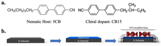
Figure 1.
(a) Chemical structures of chiral nematic liquid crystals. (b) Illustration of cell preparation process. PMMAZO brushes are coated on the cleaned wafer and grafted to the substrate through thermal annealing. Glass slides are modified by octadecyl-trichlorosilane (OTS). Two surface-modified substrates are sandwiched together to form the liquid crystal (LC) cell. The separation distance is controlled by Mylar film as spacers. The injection process needed to be conducted on the heating stage above the isotropic transition temperature of cholesteric liquid crystals (CLCs).
The helical structure of CLCs on the surface of different PMMAZO brush densities has been analyzed by the birefringence phenomenon of the liquid crystal cell under crossed polarized optical microscopy. When the helix axis of the spontaneously formed CLCs helical structure is parallel to the substrate, the homeotropic anchoring condition on the surface induces the CLCs molecules lying perpendicular to the surface and gradually transiting into parallel by the twisting power. Such periodic homeotropic and planar anchoring of CLCs molecules can be observed as fingerprint morphology, long-range order stripes (or ULH), or dendritic pattern under crossed polarized microscopy with alternating bright and dark regions [31]. Figure 2 shows lying-down helical structures of CLCs over the confined surface with different grafting densities of the PMMAZO brush and cell thicknesses. The optical images on the left column of Figure 2 present the CLC confined under the homeotropic anchoring on both OTS-modified substrates. The long axis of helical structure is parallel to the surface, therefore recognizing fingerprint morphology. When cell thickness is between 100 nm and 6 μm, the morphologies are dominated by striped patterns; simultaneously, more defects appeared as the thickness increases while the dendritic patterns were observed more frequently. As the thickness continued to increase, the long-range order stripes started to rearrange into fingerprint domains with recognizable domains at 7.5 μm cell thickness. When the cell thickness increased to 8.5 μm, uniform fingerprint patterns expanded across the entire cell surface. As the cell thickness increased from 7.5 to 8.5 μm, the fingerprint domain size decreased from average 71.3 μm to 52.0 μm (Figure 3a) in the competition with the presence of more fingerprint domains. The transition from long-range ordered lying-down helix to fingerprint domains is observed only by changing the cell thickness.
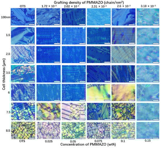
Figure 2.
Morphologies of CLCs confined in cells of different cell thicknesses and grafting densities of PMMAZO. The scale bar is 25 μm.
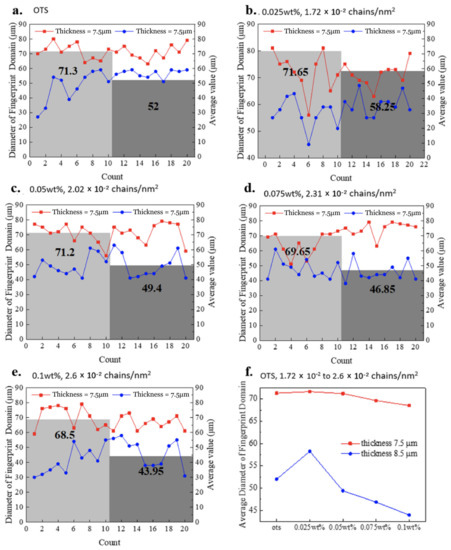
Figure 3.
The average size of fingerprint domain in cells of 7.5 μm and 8.5 μm thicknesses. The top surface of cell is always OTS-modified. The condition on bottom surfaces varies: (a) OTS-modified; PMMAZO-modified with different concentrations and grafting densities (b) 0.025wt%, 1.72 × 10⁻² chains/nm2; (c) 0.05wt%, 2.02 × 10⁻² chains/nm2; (d) 0.075wt%, 2.31 × 10⁻² chains/nm2; (e) 0.1wt%, 2.6 × 10⁻² chains/nm2. (f) The trend of fingerprint domain size with surface conditions.
For the cells consisting of OTS-modified top surface and PMMAZO-modified bottom surface, the PMMAZO grafting density varies from 1.72 × 10⁻² chains/nm2 to 2.6 × 10⁻² chains/nm2. As shown in Figure 2, long-range order striped patterns are observed between 100 nm to 6 μm cell thickness. Especially, the uniform lying-down helical structure (ULH) is stabilized when the grafting density of PMMAZO brush is 1.72 × 10⁻² chains/nm2 and 2.02 × 10⁻² chains/nm2. However, the defects appear when the cell thickness increased from 1.5 μm to 6 μm, and these defects are not the dendritic shapes found in the column of the OTS-modified both surfaces. The formation of defects is caused by the fracture of stripes. Two defects exhibiting the opposite directions of motion appear, and they are wiped out until other defects with opposite signs are encountered. Similar to the above-mentioned cells with both OTS-modified substrates, the stripe patterns are deformed into fingerprint domains, accompanied by some disclination lines, when the cell thickness becomes thicker than 6 μm. The fingerprint domains becoming more uniform, the domain size becomes smaller in 8.5 μm thickness cells compared to 7.5 μm thickness cells for (Figure 3b−e), and it slightly decreases with the increase of the grafting density (Figure 3f). When the grafting density is larger than 2.6 × 10⁻² chains/nm2, up to 3.18 × 10⁻² chains/nm2 as shown in Figure 2, blur and dislocated fingerprint patterns are observed. A similar behavior occurs when the PMMAZO grafting density is maintained at 1.72 × 10⁻² chains/nm2, while the cell thickness increases to be greater than 8.5 μm (Figure 4).
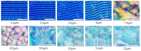
Figure 4.
Morphologies transition of CLCs confined in cells of OTS-modified top surface and PMMAZO-modified bottom surface (0.025 wt% PMMAZO solution, 1.72 × 10⁻² chains/nm2) with different cell thicknesses. The scale bar is 10 μm.
In order to gain additional insights on the morphology adopted by the CLCs, we performed continuum simulations based on the Landau-de Gennes formalism. We considered a pitch of 1 µm, two channel thicknesses h = p/2, p and the anchoring energy was varied to impose weak, moderate, and strong anchoring conditions. Figure 5 shows simulations results of a CLC confined into a channel with homeotropic top and bottom surfaces (HH-channel), and thickness h = p*/2. In all the cases, the anchoring conditions favored a lying helical structure. As expected, the free energy increases with the anchoring energy and for the case with the strongest anchoring we observe the formation of line defects at the top and bottom surfaces (W* = 1 in reduced units ~ 10−3 Jm−2). The simulated crossed polarizer images show a stripe pattern with a p/2 periodicity. Simulations are also performed for the hybrid case (HP-channel) with h = p/2. The top surface was kept with a strong homeotropic anchoring and we changed the anchoring energy of the planar bottom surface. Figure 6 shows notable differences with respect to the previous case. First, the lying helical structures is deformed, the stripe patterned is blurred—since the planar anchoring surface induces splay/bend distortions—and shows a periodicity larger than that obtained for the homeotropic channel.
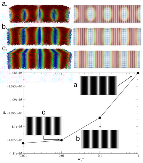
Figure 5.
Simulations of a CLC confined in a homeotropic (top/bottom) channel. (Top) Images of the lying helical structure for different anchoring energies and the corresponding 2D lateral projections, (a) strong anchoring at both surfaces, (b) moderate anchoring, and (c) weak anchoring. The colormap goes from red to blue, where red is for parallel alignment and blue is for perpendicular alignment with respect to the z axis. (Bottom) Free energy as a function of the anchoring energy, and the insets correspond to cross-polarizer images.
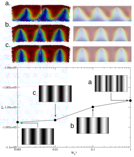
Figure 6.
Simulations of a CLC confined in a hybrid channel. The top homeotropic anchoring is kept as W*H = 1.0. (Top) Images of the obtained configurations at different anchoring energies and the corresponding 2D lateral projections, (a) strong planar anchoring at bottom surfaces, (b) moderate planar anchoring and (c) weak planar anchoring. Colormap as in Figure 5. (Bottom) Free energy as a function of the anchoring energy, the insets correspond to cross-polarizer images.
Figure 7 (left) shows results for strong anchoring conditions in both HH and HP channels, the thickness is the same as the pitch. Figure 7a,b shows two possible configurations for the HH-channel. Figure 7a corresponds to the stable state; it is a tilted helix structure and the lateral (x-view) 2D projection indicates the formation of line defects at the proximity of interfaces, where the top and bottom line defects are intercalated along the y-axis. The tilted helicoidal symmetry induces a blur stripe pattern in the simulated crossed polarizer images; this pattern has a shorter period than the one observed for the h = p/2 case. Figure 7b shows the metastable case, where the lying helical symmetry is not deformed and the simulated crossed polarizer image contains a well-defined stripe pattern with period p/2; however, this configuration has larger free energy than the tilted helix symmetry. Similarly, Figure 7c,d shows the stable and metastable configurations for the HP-channel with strong anchoring at both surfaces. Figure 7 (right) also shows the free energy as function on the anchoring energy for the HH and HP channels along the crossed polarizer images and their characteristic blur appearance due to the deformation of the helicoidal symmetry of the CLC.
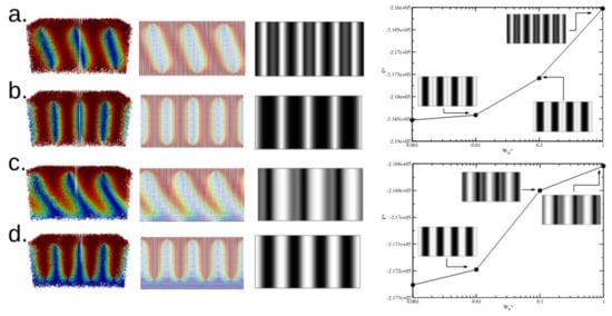
Figure 7.
HH (Homeotropic anchoring on both surfaces) and HP (Homeotropic-planar anchoring) channels. (Left) Stable and metastable states under strong anchoring conditions (a) stable state in an HH-channel, (b) metastable state in an HH-channel, (c) stable state HP-channel, and (d) metastable state in a HP-channel. (Right) Free energy as a function of the anchoring energy for HH and HP channels with channel thickness h = p.
Our simulation results can help us to explain what we observe in the experiments. From the thermodynamic point of view, twist deformation is more favoured than the splay, and bend is the more energy-consuming deformation. By increasing grafting density, the end of helix fixed on the substrate deviates further from the homeotropic direction and gained tilted orientation. Such tilted orientations induce more splay and bend deformation causing an increase in the total elastic free energy. Therefore, greater grafting density increases dislocated lines. Eventually, when the surface grafting density exceeds a certain point (at 3.18 × 10⁻² chains/nm2) and the orientation of helical structure becomes further elevated, the increase in elastic energy drive the system away from the free energy minimum to generate blur and largely dislocated fingerprint patterns. Thirdly, when the cell thickness becomes too large relative to the pitch of CLC, the surface anchoring could not stabilize the increased chiral torque, and the continuity of the helical structure is hard to be maintained, thereby resulting in the disruption of the original long and coherent lying down helical structures.
The relationship between the period of striped patterns and grafting densities are quantitively studied. The thickness of cells varies from 1.5 to 12 μm by using Mylar spacers, and the cells without spacers are determined to be ~100 nm. Obvious striped patterns could only be observed when CLCs are confined in the cells with certain thicknesses as shown in Figure 2. When the thicknesses become larger than 6 μm, the fingerprint domains appeared. The disorder stripes caused by the formation of fingerprint leads to inadequacy of dimension evaluation. Figure 8a describes the measured period of lying helical structure under different surface anchoring and cell thicknesses. Firstly, the period decreases when the grafting density of PMMAZO increases. The stretched chain conformation of a PMMAZO brush at a higher grafting density induces the increase of the angle between the axis of mesogenic side chain and the normal of substrate [32]. Therefore, the orientation of CLC molecules on the modified substrate change from perpendicular (OTS-modified surface) to tilted with the increasing grafting density of PMMAZO. Based on our simulations, we can assume that one end of the CLC helix was fixed to the top glass surface (OTS-modified, homeotropic anchoring), the CLC molecules are forced to lie perpendicular to the surface; the other end of the helix is varied on the silicon substrate (PMMAZO-modified, tilted anchoring), and the CLC molecules close to the substrate follow along the particular orientation (Figure 8b). The overall helical structure is deformed to satisfy the anchoring constrains from both surfaces. As a result of the deformation of the helical structure, the period of striped pattern decreases with the larger tilt angle. In other words, inclination of the helical axis caused by the grafting density change of the polymer brush alters the pitch size of CLC to compensate the strain imposed on molecules. Note that in periodic striped patterns, a period represents a half pitch of CLC.
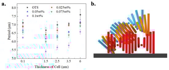
Figure 8.
(a) Periods of long-range order stripes as function of PMMAZO brush solution concentration. The grafting densities of PMMAZO corresponding to the concentrations are 1.72 × 10⁻² chains/nm2, 2.02 × 10⁻² chains/nm2, 2.31 × 10⁻² chains/nm2, 2.6 × 10⁻² chains/nm2, respectively. (b) Illustration shows the degree of tilting of helix varies with surface anchoring. The red color schematic diagram represents CLC confined in OTS-modified cell with a long axis of helix parallel to the substrate. Orange and blue color schematics represent degrees of tilting of helices in cells with different grafting densities: Orange—lower grafting density and blue—higher grafting density.
The period of the lying-down helix texture increases with the spacer thickness; however, when the cell is prepared without spacers and the thickness is kept at ~100 nm as an extremely thin cell, the period of CLC is obviously larger than that in the 1.5-μm-thick cell (Figure 8a). When CLC is confined in an extremely thin cell, the helical structure is horizontal in order to satisfy both boundary anchoring conditions; meanwhile, CLC molecules adopt a more splayed deformation other than a bend to minimize the elastic energy of the CLC system. The mechanism here is different than the increment of formed stripe pattern when cell thicknesses are larger than 1.5 μm, which is due to the elongation of pitch at the vertical direction to accommodate the boundary anchoring conditions. The relationship between the period of striped pattern and the grafting density of PMMAZO in the 100-nm-thick cells is identical to that in other grafting density cells.
3. Conclusions
In this study, we investigate the morphological transition of a chiral nematic liquid crystal along with dimensional control by changing the surface anchoring and thickness of the confined cell. A liquid crystalline polymer brush, PMMAZO, offers an effective way to tune the orientation and morphology of CLCs by simply varying the grafting density. The uniform long-range order stripe patterns or lying-down helical structures of CLCs are observed for lower PMMAZO grafting densities (1.72 × 10⁻² chains/nm2–2.02 × 10−2 chains/nm2) at cell thickness ranging from 1.5 μm to 6 μm. Such a long-range order lyin-down helix (or stripe pattern) is gradually replaced by either fingerprint domains until uniform fingerprint domains spread out in the cell when the thickness increases up to 7.5 μm, or dislocated fingerprint patterns until PMMAZO grafting density reaches 3.18 × 10⁻² chains/nm2. Furthermore, we found that anchoring energy and cell thicknesses influences the stripe pattern period: When the graft density of PMMAZO increases, the period of the stripe pattern decreases, and when the cell thickness increases, the period of the stripe pattern increases. The mechanism of CLCs morphology change under different anchoring conditions is revealed as: The PMMAZO brush with a mesogenic side chain provides limited freedom of tilting of LC molecules on the surface, thereby facilitating the long-range order. The increase of grafting density of PMMAZO induces the greater degree of tilting, which causes more splay and bend deformation to further increase the total free energy, thereby resulting in more defects and dislocations. Controlling the substrate anchoring by varying the grafting density of polymer brushes provides an effective method to stabilize the uniform lying helix in CLC system without any external supports, which is essential to the formation of LC gratings and the optical devices based on them.
4. Experimental Section
Materials. 5CB (4-pentyl-4-biphenylcarbonitrile) was purchased from Sigma-Aldrich (Figure 1). 5CB exhibits a nematic phase at room temperature and the temperature of a LC-isotropic phase transition at 35°C. The chiral dopant is CB15 ((s)-4’-Methylbutyl) (1,1’-biphenyl)-4-carbonitrile), which was purchased form Merck. Heptane, isopropyl alcohol, octadecyl-trichlorosilane (OTS), and chlorobenzene were purchased from Sigma-Aldrich. PMMAZO, poly (6-(4-methoxy-azobenzene-4’-oxy) hexyl methacrylate), was obtained by the process reported by Stewart and Imrie [33]. Silicon wafers were purchased from Wafer Pro. Glass slides were purchased from Fisher Scientific.
Surface modification. Glass slides and silicon wafers were placed in piranha solution (7:3 of H2SO4 and H2O2) at 120°C for 1 h to clean surfaces. Glass slides and silicon wafers in the OTS group were OTS-modified by immersing in OTS solution (13.8 μL OTS/120 mL heptane) for 1 h. For PMMAZO-modified silicon wafers, polymer brush thin films were coated on silicon wafers by spin-coating a PMMAZO solution (0.025 wt%–0.1 wt% PMMAZO/ chlorobenzene) at 4000 rpm for 1 min then annealing the wafers at 250 °C in nitrogen for 5 min. Afterwards, wafers were sonicated in chlorobenzene for 5 min and repeated three times. All surfaces were quickly dried by nitrogen after completing the modification processes.
Cell preparation. For the OTS group, cells were prepared with OTS-modified glass slides and OTS-modified wafers. The assembly process is demonstrated by the schematic (Figure 1). Mylar thin films with different thicknesses were used to create the gap distance between two surfaces. LC cells and CLCs (6 wt% of CB15) were heated to 45 °C on the heating stage, and 4 μL of CLCs was injected from one side of the cell. The heating stage was then turned off and the cells naturally cooled down to room temperature. For the PMMAZO group, its assembly procedure is the same as that of OTS group, except that PMMAZO-modified wafers were replaced by OTS-modified wafers.
Characterization. Images of CLC cells were obtained by polarization microscopy (BX53 Olympus). Periods of striped pattern and sizes of fingerprint domains were measured by the image processing program (ImageJ). PMMAZO film thicknesses were measured by alpha-SE ellipsometer. Contact angles of the modified wafers were measured by Dataphysics measuring device. Compensator angles were measured by U-CTB Berek compensator (Olympus).
5. Simulations
Under the Landau-de Gennes framework, the free energy of the confined CLC is given by [34,35],
where Q is the tensor given by Qij = S (ni nj -1/3 δij), S is the scalar order parameter, and ni is the components of the local director vector (i, j = 1,2,3). F(Q) accounts for short-range interactions (fLdG), long-range elastic contributions (fE), and surface contributions (fS). The first term in Equation (3) is given by,
where A sets the density energy scale, U is a dimensionless parameter that determines the value of the equilibrium scalar order parameter S via, The elastic term in Equation (3), in the so-called one constant approximation, is given by,
where L is an elastic constant, εikl is the Levi-Civita tensor, and p is the pitch, which depends on the chirality of the system via q0 = 2π/p.
The surface energy in Equation (3) depends on the anchoring conditions. For planar-degenerate anchoring it is given by [36], , where WP is the planar anchoring energy, S0 is the surface preferred degree of order, and , where P is given by with ν the vector normal to the surface. For homeotropic anchoring, , where WH is the homeotropic anchoring energy and Q0 is a surface-preference tensor order parameter.
The Q-tensor contains all the information about the structure of the LC phase and it was determined by minimization of the free energy functional using the Euler-Lagrange formalism and the finite difference method. To this end, we employed a simulation box consisting of a grid, where h corresponds to the channel thickness (h = 50 or 100), a grid resolution of one coherence length was considered. The Q-tensor evolved toward equilibrium according to the Ginzburg-Landau relaxation method,
where γ is a diffusion coefficient, the operator is given by and ensures the symmetric and traceless properties of the Q-tensor. The boundary conditions satisfy , where ν is the normal vector to the surface. We report results in reduced units as follows: For the reduced anchoring energy, , where and are the coherence and the extrapolation length respectively; for the pitch we have ; and the free energy is reduced as follows . Typical values for the elastic constant and the coherence length are in the order of pN and ~10 nm, respectively [34,35].
Author Contributions
Conceptualization, X.L. and J.A.M.-G; methodology, Z.J. and X.L.; validation, J.A.M.-G. and G.I.G.-G.; data curation, X.L. J.A.M.-G., G.I.G.-G. and Z.J.; writing—original draft preparation, Z.J., T.P., J.A.M.-G. and X.L.; writing—review and editing, S.H. and G.I.G.-G.; supervision, X.L.; funding acquisition, X.L. and J.A.M.-G. All authors have read and agreed to the published version of the manuscript.
Funding
X.L. acknowledges support of startup funding from University of North Texas. J.A.M.-G. acknowledges support from Ciencia de Frontera CONACYT grant No. CF-2019-74885 and computer resources, technical advice, and support provided by the Laboratorio Nacional de Supercómputo del Sureste de México (LNS), a member of the CONACYT national laboratories, with project no. 201901023N.
Data Availability Statement
All the information and the necessary data to support the findings of this paper are provided in the manuscript; additional information regarding simulations and experiments can be requested the authors.
Acknowledgments
We acknowledge the University of North Texas’ Materials Research Facility. We thank Rick Reidy for the useful discussion on polymer surface characterization.
Conflicts of Interest
The authors declare no competing financial interests.
References
- Vignolini, S.; Rudall, P. Pointillist structural color in Pollia fruit. Proc. Natl. Acad. Sci. USA 2012, 109, 15712–15715. [Google Scholar] [CrossRef] [PubMed]
- Parker, A.; Mckenzie, D. Multilayer reflectors in animals using green and gold beetles as contrasting examples. J. Exp. Biol. 1998, 201, 1307–1313. [Google Scholar]
- Raabe, D.; Sachs, C. The crustacean exoskeleton as an example of a structurally and mechanically graded biological nanocomposite material. Acta Mater. 2005, 53, 4281–4292. [Google Scholar] [CrossRef]
- Wilts, B.; Whitney, H. Natural Helicoidal Structures: Morphology, Self-assembly and Optical Properties. Mater. Today Proc. 2014, 1, 177–185. [Google Scholar] [CrossRef]
- Saha, A.; Tanaka, Y. Irreversible visual sensing of humidity using a cholesteric liquid crystal. Chem. Commun. 2012, 38, 4579–4581. [Google Scholar] [CrossRef]
- Kelly, J.; Giese, J. The Development of Chiral Nematic Mesoporous Materials. Acc. Chem. Res. 2014, 47, 1088–1096. [Google Scholar] [CrossRef] [PubMed]
- Wilts, B.; Dumanli, A. Chiral optics of helicoidal cellulose nanocrystal films. APL Photonics 2017, 2, 040801. [Google Scholar] [CrossRef]
- Coles, H.; Morris, S. Liquid-crystal lasers. Nat. Photonics 2010, 4, 676–685. [Google Scholar] [CrossRef]
- Mitov, M.; Dessaud, N. Going beyond the reflectance limit of cholesteric liquid crystals. Nature 2006, 5, 361–364. [Google Scholar] [CrossRef] [PubMed]
- Oswald, P.; Pieranski, P. Nematic and Cholesteric Liquid Crystals: Concepts and Physical Properties Illustrated by Experiments; CRC Press: Boca Raton, FL, USA, 2005. [Google Scholar]
- Dierking, I. Textures of Liquid Crystals; Wiley-VCH: Weinheim, Germany, 2003. [Google Scholar]
- Patel, J.; Meyer, R. Flexoelectric electro-optics of a cholesteric liquid crystal. Phys. Rev. Lett. 1987, 58, 1538. [Google Scholar] [CrossRef] [PubMed]
- Laudyn, U.; Kwasny, M. Light beam steering in chiral nematic liquid crystals. In Proceedings of the 2009 3rd ICTON Mediterranean Winter Conference (ICTON-MW), Angers, France, 10–12 December 2009; pp. 1–3. [Google Scholar]
- Faklis, D.; Morris, G. Diffractive optics technology for display application. SPIE 1995, 2407, 57–61. [Google Scholar]
- Rudquist, P.; Komitov, L. Linear electro-optic effect in a cholesteric liquid crystal. Phys. Rev. E 1995, 50, 4735–4743. [Google Scholar] [CrossRef] [PubMed]
- Matsushit, T.; Goh, M. Vertically aligned helical polyacetylene synthesized in chiral nematic liquid crystal under magnetic field. Curr. Appl. Phys. 2006, 6, 952–955. [Google Scholar] [CrossRef]
- Zheng, Z.; Li, Y. Three-dimensional control of the helical axis of a chiral nematic liquid crystal by light. Nature 2006, 531, 352–356. [Google Scholar] [CrossRef] [PubMed]
- Kim, S.; Chien, L. Short pitch cholesteric electro-optical device stabilized by nonuniform polymer network. Appl. Phys. Lett. 2005, 86, 161118. [Google Scholar] [CrossRef]
- Carbone, G.; Salter, P. Short pitch cholesteric electro-optical device based on periodic polymer structures. App. Phys. Lett. 2009, 95, 1538. [Google Scholar] [CrossRef]
- Rudqusit, P.; Komitov, L. Volume-stabilized ULH structure for the flexoelectro-optic effect and the phase-shift effect in cholesterics. Liq. Cryst. 1998, 24, 329–334. [Google Scholar] [CrossRef]
- Park, K.; Baek, J. Effects of pretilt angle and anchoring energy on alignment of uniformly lying helix mode. Liq. Cryst. 2016, 43, 1184–1189. [Google Scholar] [CrossRef]
- Komitov, L.; Bryan-Brown, G. Alignment of cholesteric liquid crystals using periodic anchoring. J. Appl. Phys. 1999, 86, 3508. [Google Scholar] [CrossRef]
- Outram, B.; Elston, S. Spontaneous and stable uniform lying helix liquid-crystal alignment. J. Appl. Phys. 2013, 113, 1538. [Google Scholar] [CrossRef]
- Carbone, G.; Corbett, D. Uniform Lying Helix Alignment on Periodic Surface Relief Structure Generated via Laser Scanning Lithography. Liq. Cryst. 2011, 544, 37–49. [Google Scholar] [CrossRef]
- Tartan, C.; Salter, P. Localised polymer networks in chiral nematic liquid crystals for high speed photonic switching. J. Appl. Phys. 2016, 119, 183106. [Google Scholar] [CrossRef]
- Li, X.; Bishop, C. Engineering the Anchoring Behavior of Nematic Liquid Crystals on Solid Surface by Varying the Density of Liquid Crystalline Polymer Brush. Soft Matter 2018, 14, 7569–7577. [Google Scholar] [CrossRef]
- Li, X.; Armas-Pérez, J. Directed Self-Assembly of Colloidal Particles onto Nematic Liquid Crystalline Defects Engineered by Chemically Patterned Surfaces. ACS Nano 2017, 11, 6492–6501. [Google Scholar] [CrossRef] [PubMed]
- Yanagimachi, T.; Li, X. Surface anchoring of nematic liquid crystal on swollen polymer brush studied by surface forces measurement. Adv. Colloid. Interface. Sci. 2019, 272, 101997. [Google Scholar] [CrossRef]
- Li, X.; Julio, A. Directed self-assembly of nematic liquid crystals on chemically patterned surfaces: Morphological states and transitions. Soft Matter 2016, 12, 8595–8605. [Google Scholar] [CrossRef]
- Miller, D.; Carlton, R. Introduction to optical methods for characterizing liquid crystals at interfaces. Langmuir 2013, 29, 3154–3169. [Google Scholar] [CrossRef]
- Nagaya, Y.; Hikita, Y. Numerical study of the growth of the cholesteric finger pattern. J. Phys. Soc. Jpn. 1996, 65, 2713–2716. [Google Scholar] [CrossRef]
- Hamelinck, P.; Huck, W. Homeotropic alignment on surface-initiated liquid crystalline polymer brushed. J. Mater. Chem. 2005, 15, 381–385. [Google Scholar] [CrossRef]
- David, S.; Imrie, C. Synthesis and characterization of spin-labelled and spin-probed side-chain liquid crystal polymers. Polymer 1996, 37, 3419–3425. [Google Scholar]
- Ravnik, M.; Žumer, S. Landau–de Gennes modeling ofnematic liquid crystal colloids. Liq. Cryst. 2009, 36, 1201–1214. [Google Scholar] [CrossRef]
- Martinez-Gonzalez, J.; Li, X. Directed self-assembly of liquid crystalline blue-phases into ideal single-crystals. Nat. Commun. 2017, 8, 15854. [Google Scholar] [CrossRef] [PubMed]
- Fournier, J.; Galatola, P. Modeling planar degenerate wetting and anchoring in nematic liquid crystals. Europhys. Lett. 2005, 72, 403–409. [Google Scholar] [CrossRef]


Publisher’s Note: MDPI stays neutral with regard to jurisdictional claims in published maps and institutional affiliations. |
© 2021 by the authors. Licensee MDPI, Basel, Switzerland. This article is an open access article distributed under the terms and conditions of the Creative Commons Attribution (CC BY) license (https://creativecommons.org/licenses/by/4.0/).