Article

Three-Dimensionally Ordered Macroporous La2O3-Supported Ni Catalyst for Methane Dry Reforming

1
College of Water Sciences, Beijing Normal University, No. 19 Xinjiekouwai Street, Beijing 100875, China
2
Beijing Qinghuan Energy Technology Co., Ltd., Beijing 100029, China
3
Department of Chemistry, ”Sapienza” University of Rome, Piazzale Aldo Moro, 5, 00185 Rome, Italy
*
Author to whom correspondence should be addressed.
Catalysts 2025, 15(10), 992; https://doi.org/10.3390/catal15100992 (registering DOI)
Submission received: 10 September 2025 / Revised: 4 October 2025 / Accepted: 7 October 2025 / Published: 17 October 2025

Abstract

Three-dimensionally ordered macroporous (3DOM) La2O3-supported Ni catalysts exhibit outstanding performance for methane dry reforming (DRM). The 5Ni/La2O3-3DOM catalyst achieves 79% CH4 and 84% CO2 conversions at 800 °C under the reaction conditions of atmospheric pressure, CH4:CO2 molar ratio of 1:1, and gas hourly space velocity (GHSV) = 36,000 mL·gcat−1·h−1, outperforming its counterparts (5Ni/La2O3-PP prepared by means of co-precipitation and 5Ni/La2O3-GNC prepared by means of glycine–nitrate combustion) by 15–20%. Long-term stability tests at 700 °C (same CH4:CO2 ratio and GHSV as above) show that the 5Ni/La2O3-3DOM catalyst maintains CH4 and CO2 conversions at approximately 80% and 85%, respectively, with zero deactivation over 50 h. Meanwhile, its carbon deposition rate plummets to 1.1 mg·g−1·h−1, which is 75% lower than that of the precipitation-derived 5Ni/La2O3-PP catalyst. This excellent performance stems from the synergy of nano-confined Ni particles (11.2 nm in crystallite size after reduction) and abundant surface oxygen species (38 μmol·g−1), establishing 3DOM La2O3 as a superior anti-coking support platform for scalable H2 production via DRM.

Graphical Abstract

1. Introduction

Energy serves as the fundamental cornerstone of human survival, a pivotal driver of modern economic development, and a critical strategic resource for national progress [1]. However, the environmental pollution stemming from energy consumption and the challenges posed by energy scarcity have cast severe shadows over the survival and development of human society [2]. Hydrogen energy, distinguished by its exceptional calorific value—releasing approximately three times more heat than gasoline, 3.9 times more than alcohol, and 4.5 times more than coke when combusted—and its clean combustion product (pure water), is widely regarded as the cleanest energy source globally [3,4]. Consequently, hydrogen energy is poised to become a pivotal secondary energy carrier in the 21st-century energy landscape.
Methane, the primary component of natural gas and shale gas, boasts high calorific value and easy accessibility, making it indispensable in both daily life and industrial production [5,6]. Nevertheless, the environmentally friendly and efficient utilization of methane remains a pressing challenge for humanity. Industrial methane conversion pathways can be categorized into direct and indirect approaches [7,8]. Direct conversion aims to transform methane into high-value chemicals such as methanol, formaldehyde, ethylene, and aromatics. However, methane exhibits extraordinary structural stability, with a C-H bond dissociation energy of 439.3 kJ/mol, leading to exorbitant energy consumption during conversion. Compounded by low product yields and poor economic viability, direct methane conversion has yet to achieve industrialization [9,10,11].
In contrast, indirect methane conversion—converting CH4 into syngas (H2/CO) for subsequent production of downstream chemicals via Fischer–Tropsch synthesis—currently represents the most prevalent and mature method for methane utilization [12]. There are four primary routes for indirect methane-to-syngas conversion: methane steam reforming, methane autothermal reforming, methane partial oxidation, and methane dry reforming (DRM) [13,14]. Among these, DRM (CH4 + CO2 → 2H2 + 2CO) holds unique environmental and economic significance: it simultaneously valorizes two of the most abundant and stable greenhouse gases (CH4 and CO2), converting them into syngas with an H2/CO ratio close to 1—ideal for Fischer–Tropsch fuel synthesis and fuel-cell-grade hydrogen production. Additionally, the DRM reaction’s substantial heat effect enables it to function as an energy storage medium [15,16,17,18], aligning with global carbon neutrality goals.
The support plays a decisive role in the performance of catalysts for methane dry reforming (DRM). Its core functions are to disperse and stabilize active metal components, inhibit the sintering and agglomeration of metal particles, and thereby improve catalytic activity and durability. An ideal catalyst support should possess a relatively high specific surface area and excellent thermal stability [19,20,21]. In recent years, three-dimensionally ordered macroporous (3DOM) materials have shown broad application prospects in various fields, including membrane materials, biomaterials, photonic crystals, battery materials, enzyme carriers, separation materials, and heterogeneous catalysis [22,23]. These materials have interconnected and uniform pores (pore size > 50 nm), which not only shorten mass transfer paths and suppress the generation of local hotspots but also immobilize metal nanoparticles within rigid pore walls, effectively retarding metal sintering [24,25]. The colloidal crystal templating method has become one of the most commonly used methods for preparing 3DOM materials due to its simple preparation process, low raw material cost, and easy regulation of pore structure [26]. When the 3DOM structure is combined with rare-earth oxides such as La2O3 (which have high oxygen mobility and strong CO2 adsorption capacity), it can not only accelerate carbon deposition gasification by virtue of abundant reactive oxygen species but also stabilize ultrafine Ni particles through strong metal–support interaction. This enables the simultaneous solution of the two core problems (metal sintering and carbon deposition-induced deactivation) in the DRM reaction within a single structure [27,28].
To verify the above hypothesis, three types of La2O3 supports with different structures were synthesized in this study via colloidal crystal templating (for preparing 3DOM structure), glycine combustion, and co-precipitation methods, respectively. Subsequently, a series of catalysts were prepared by loading Ni onto these supports, and the DRM performance (activity, stability, and carbon deposition resistance) of these catalysts was systematically evaluated [29]. The structure–activity relationship of the catalysts was elucidated through various characterization techniques. This study aims to provide a new strategy for designing high-performance DRM catalysts and promote the industrialization of methane dry reforming technology.

2. Results and Discussion

2.1. Structure Characterization of Supports

Figure 1 presents the SEM images of the PMMA hard template and La2O3 supports prepared by means of different methods in this study. Figure 1A displays uniformly sized PMMA microspheres arranged in a three-dimensionally ordered manner, with an average particle size of 280 nm calculated from the image. Figure 1B is the SEM image of the La2O3-3DOM support, where a three-dimensionally ordered macroporous structure is clearly observable. The macropores are uniformly and orderly arranged, which can enhance the specific surface area of the catalyst and significantly improve its catalytic activity. Figure 1C,D represent the La2O3 supports prepared by means of the precipitation and glycine methods, respectively. Compared to Figure 1B, the pore channels of the supports are unevenly distributed, vary in size, and exhibit irregular shapes. Therefore, the colloidal crystal templating method successfully prepared the three-dimensionally ordered macroporous La2O3-3DOM support.
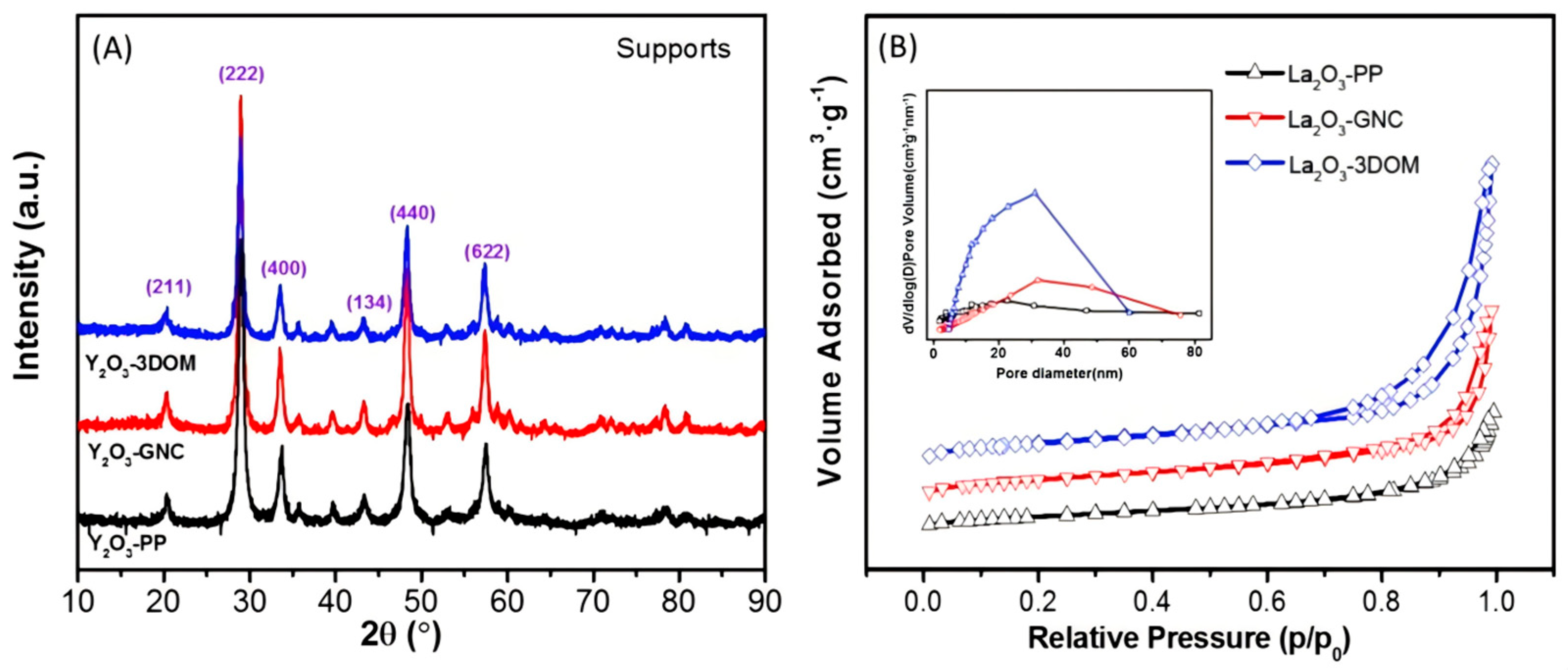
Figure 2A presents the XRD patterns of the three La2O3 supports, from which it can be observed that the prepared La2O3 samples all exhibit a cubic crystal structure. By comparison, the La2O3-PP support shows the highest intensity of diffraction peaks, indicating the best crystallinity and possibly the smallest specific surface area. The grain sizes of the La2O3 supports were calculated using Scherrer’s formula and are presented in Table 1, with the order being: La2O3-PP > La2O3-GNC > La2O3-3DOM. The 3DOM support prepared using a double template has the smallest grain size.
To investigate the specific surface area and pore structure of the La2O3 supports, N2 adsorption–desorption tests were conducted on each support. Figure 2B shows the adsorption–desorption isotherms and pore size distribution of the La2O3 supports, with a clear hysteresis loop observable on the 3DOM support, indicating the presence of mesoporous structures. All supports exhibit Type IV adsorption–desorption curves with H3 type hysteresis loops, suggesting that the catalysts have a stacked pore structure. The pore volumes of the three supports were quantified, and the results are presented in Table 1. The order of pore volume and specific surface area for La2O3 supports prepared by different methods is La2O3-3DOM > La2O3-GNC > La2O3-PP, with La2O3-3DOM having the largest pore volume and specific surface area, which are 0.29 cm3·g−1 and 62 m2·g−1, respectively.

2.2. Activity and Stability Evaluation

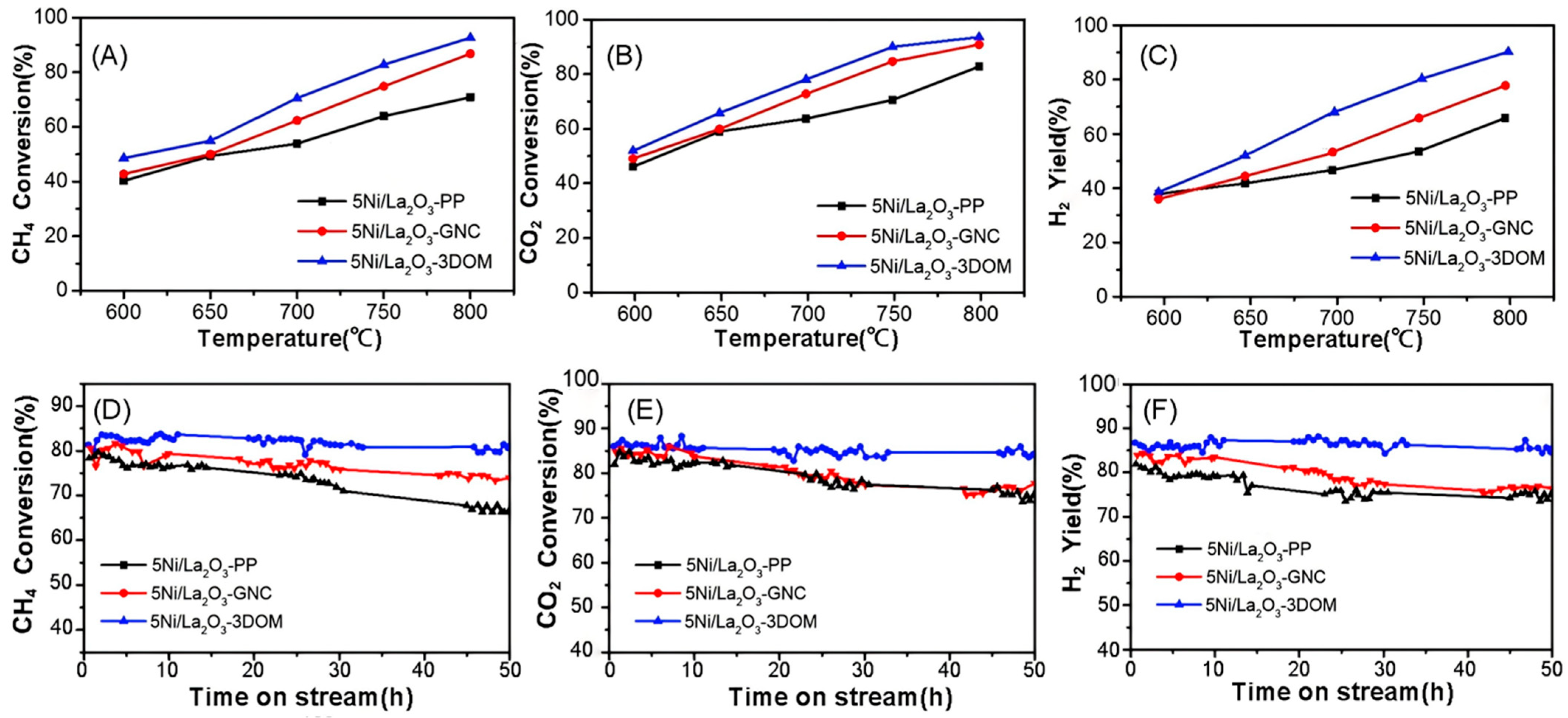
Catalytic activity differences among the various catalysts for the DRM reaction were evaluated using a feed gas mixture of CH4 and CO2 (1:1 molar ratio) over the temperature range of 600–800 °C. The reaction conditions were consistent with those described in Section 2.2: atmospheric pressure, a gas hourly space velocity (GHSV) of 36,000 mL·gcat−1·h−1, and pre-reduction in a 10% H2/Ar atmosphere at 600 °C for 2 h. Prior to the activity test, all fresh catalysts were reduced in a 10% H2/Ar atmosphere. As expected for the endothermic DRM reaction, the conversions of both CH4 and CO2 increase with rising temperature. Throughout the tested range, the CO2 conversion rate was consistently higher than that of CH4. This is primarily attributed to the concurrent occurrence of the reverse water-gas shift reaction (CO2 + H2 ↔ CO + H2O) alongside the reforming reaction. Among the catalysts, 5Ni/La2O3-3DOM exhibited the highest initial activity, achieving CH4 conversions of 32% at 600 °C, 47% at 700 °C, and 79% at 800 °C, followed by 5Ni/La2O3-GNC and then 5Ni/La2O3-PP.
To further compare the catalysts’ performance, long-term stability tests were conducted at 700 °C under the conditions of CH4:CO2 = 1:1, GHSV = 36,000 mL·gcat−1·h−1, and atmospheric pressure (1 atm). The results over a 50 h period are shown in Figure 3C–E. The 5Ni/La2O3-PP catalyst experienced significant deactivation, with CH4 conversion decreasing from an initial 78% to 65% and CO2 conversion declining from 82% to 74%. In contrast, the 5Ni/La2O3-3DOM catalyst demonstrated excellent stability, maintaining CH4 and CO2 conversions at approximately 80% and 85%, respectively, with no significant decline throughout the 50 h test. The 5Ni/La2O3-GNC catalyst showed intermediate stability, and the decreasing trend of its CO2 conversion was consistent with that of the 5Ni/La2O3-PP catalyst. The superior stability exhibited by the 5Ni/La2O3-3DOM catalyst suggests enhanced resistance to deactivation under the test conditions, potentially stemming from improved Ni dispersion (smaller nanoparticles) and superior anti-coking performance, which will be further discussed in conjunction with characterization results [30,31,32].

2.3. Carbon Deposition and Resistance Mechanism

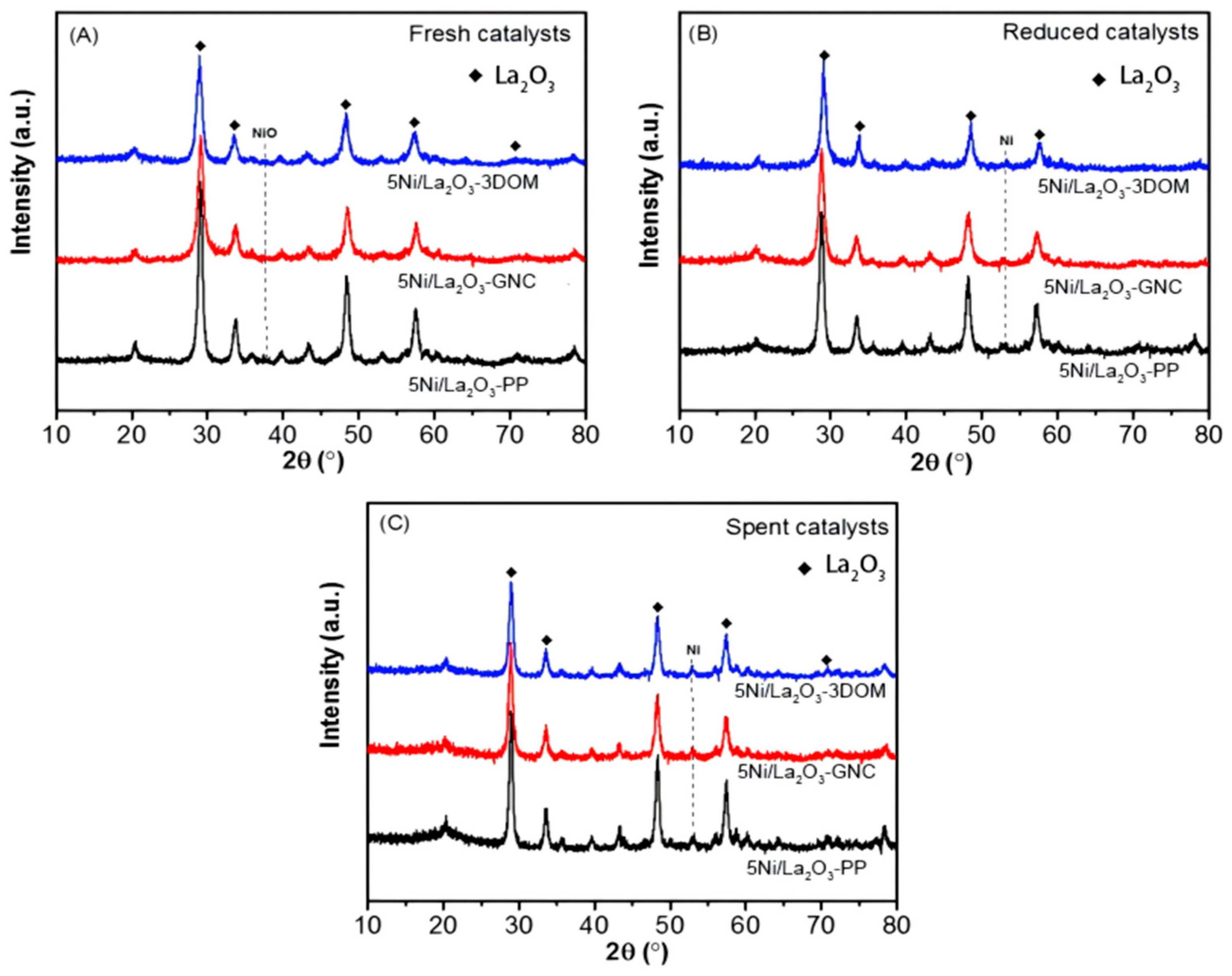
XRD was employed to investigate the crystal structure evolution of the catalysts before reduction, after reduction, and after the DRM stability test, with the results presented in Figure 4. Figure 4A displays the patterns of the fresh calcined catalysts. Diffraction peaks corresponding to the cubic phase (JCPDS 05-0602) of La2O3 support were predominant. Additionally, characteristic peaks of NiO were detected, confirming the presence of the precursor phase. The NiO crystallite sizes—estimated by applying Scherrer’s equation to the NiO (200) diffraction peak—are listed in Table 2.
Figure 4B shows the XRD patterns of the catalysts after reduction in H2. The disappearance of NiO peaks and the emergence of a peak near 2θ = 52.1° (characteristic of metallic Ni) confirm the successful reduction of NiO to Ni. The Ni crystallite sizes, calculated from the Ni peak, are also summarized in Table 2. Both the NiO crystallite sizes in the fresh catalysts and the Ni crystallite sizes in the reduced catalysts follow the order: 5Ni/La2O3-3DOM < 5Ni/La2O3-GNC < 5Ni/La2O3-PP. The significantly smaller NiO and Ni crystallites on the 5Ni/La2O3-3DOM catalyst suggest a stronger interaction between Ni species and the 3DOM support, potentially inhibiting particle aggregation. This interaction will be further probed by H2-TPR analysis.
The structural characteristics of the spent catalysts after the 50 h stability test are shown in Figure 4C. The diffraction patterns of the La2O3 support remained largely unchanged compared to the fresh catalysts (Figure 4A), demonstrating the high thermal stability of the La2O3 crystal structure under reaction conditions. The characteristic peak of metallic Ni was still present. Calculation of the Ni crystallite sizes from the Ni peak revealed growth for all catalysts during the reaction. Notably, the Ni crystallites on 5Ni/La2O3-3DOM grew from 11.2 nm (reduced state) to 14.0 nm. In contrast, the Ni crystallites on 5Ni/La2O3-GNC and 5Ni/La2O3-PP grew from 11.9 nm to 19.5 nm and from 13.8 nm to 23.5 nm, respectively—indicating that 5Ni/La2O3-3DOM exhibited enhanced resistance to Ni sintering. Furthermore, no distinct diffraction peaks attributable to graphitic carbon at ~26° 2θ were observed for any spent catalyst. This result is attributed to the low crystallinity (high disorder) and low content of deposited carbon, which falls below the detection limit of XRD for amorphous/disordered carbon (typically ≥5–10 wt% for graphitized carbon and ≥15 wt% for disordered carbon). As confirmed by subsequent Raman spectroscopy and TGA-DSC analysis, all spent catalysts do exhibit carbon deposition, but the carbon is predominantly amorphous or weakly ordered—characteristics that prevent XRD from generating detectable diffraction signals. This is consistent with the low carbon content (5.2–12.5 wt%, Table 3) quantified by means of TGA-DSC, where the highly dispersed, low-crystallinity carbon signals are masked by the stronger diffraction peaks of the La2O3 support and metallic Ni. The small initial Ni crystallite size on 5Ni/La2O3-3DOM is consistent with its observed superior initial activity for DRM.
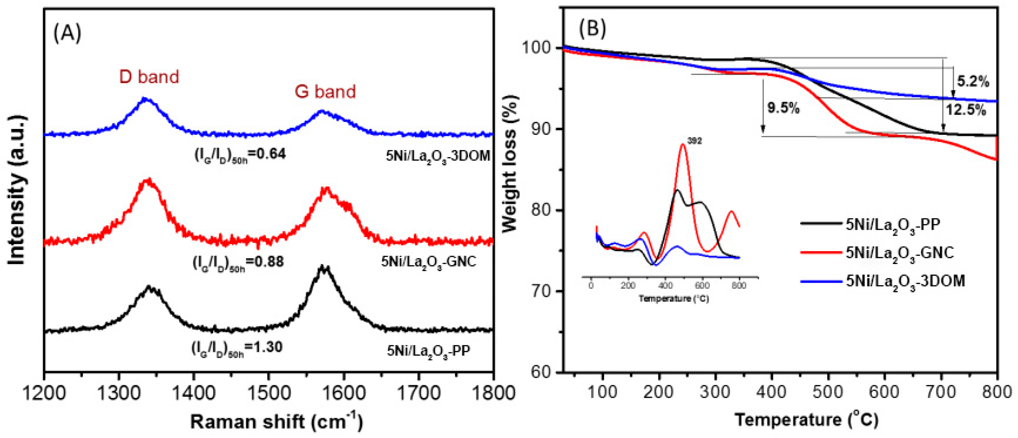
To complement the XRD results (which showed no graphitic carbon peaks) and further investigate carbon deposition, Raman spectroscopy and thermogravimetric analysis coupled with differential scanning calorimetry (TGA-DSC) were performed on the spent catalysts. The Raman spectra (Figure 5A) revealed two characteristic bands for all catalysts: the D band near 1350 cm−1 (associated with disordered/amorphous carbon) and the G band near 1580 cm−1 (corresponding to graphitic carbon). The presence of both the D band and G band indicates that carbon deposition occurred during the 50 h stability test. The intensity ratio of the G band to the D band (IG/ID) provides an indication of the graphitization degree of the deposited carbon. As listed in Table 3, the IG/ID ratio follows the order: 5Ni/La2O3-3DOM < 5Ni/La2O3-GNC < 5Ni/La2O3-PP, indicating that the carbon deposited on the 5Ni/La2O3-3DOM catalyst is the least graphitic.
TGA-DSC analysis was conducted in air (flow rate: 50 mL/min, heating rate: 10 °C/min) after pre-drying the samples at 110 °C under N2. The resulting profiles are shown in Figure 5B. Weight loss below ~350 °C is attributed to the removal of physisorbed water. The primary weight loss occurs between approximately 400 °C and 700 °C, accompanied by a strong exothermic peak in the DSC curve—this is attributed to the combustion of deposited carbon on the used catalysts. Additionally, a small weight loss accompanied by a weak exothermic peak at ~392 °C (observed in Figure 5B) is attributed to the combustion of low-molecular-weight amorphous carbon (a minor fraction of the deposited carbon), which is less stable and oxidizes at lower temperatures compared to the main carbon fraction (oxidized at 400–700 °C). For the 5Ni/La2O3-GNC catalyst, an additional weight loss step above 700 °C (accompanied by an endothermic DSC peak) is observed, which is attributed to the decomposition of lanthanum carbonate species (La2O2CO3) formed on the La2O3 surface. The amount of deposited carbon was calculated from the weight loss associated with the main exothermic combustion peak (400–700 °C). As shown in Table 3, the carbon content follows the same order as the IG/ID ratio: 5Ni/La2O3-3DOM < 5Ni/La2O3-GNC < 5Ni/La2O3-PP.
The coking rate was calculated from TGA weight loss in the 400–550 °C range (normalized to the fresh catalyst’s initial mass). Note that the carbon deposition amount (Table 3) and coking rate reported here only reflect carbon combustion in 400–550 °C, not weight loss from La2O2CO3 decomposition (which happens at ~600−700 °C). To avoid carbonate interference, we only used 400–550 °C data (verified by comparing with pure La2O2CO3′s TGA profile). For clarity, we also report the total weight loss (300–800 °C) of used catalysts: 15.2% (5Ni/La2O3-PP), 12.1% (5Ni/La2O3-GNC), 7.8% (5Ni/La2O3-3DOM). This total includes small losses from water (<400 °C), carbon combustion (400–550 °C), and carbonate decomposition (>600 °C).
These results demonstrate that the synthesis method of the La2O3 support significantly influences the catalyst’s resistance to carbon deposition during DRM. The 5Ni/La2O3-3DOM catalyst not only exhibits the highest activity and stability but also has the lowest amount of deposited carbon and the least graphitic nature of the deposited carbon. This combination of properties underscores its superior overall coke resistance compared to catalysts using La2O3 supports prepared by glycine–nitrate combustion or precipitation methods.

2.4. Metal–Support Interaction

For the quantitative analysis of H2 consumption of different NiO species (H2-TPR), CO2 desorption amount of different basic sites (CO2-TPD), and O2 desorption amount of different oxygen species (O2-TPD), all TPD/TPR profiles were deconvoluted using Origin 2023 software with specific parameters: H2-TPR adopted Gaussian multi-peak fitting (two peaks: α peak at 330–380 °C for NiO with weak support interaction, β peak at 380–600 °C for NiO with strong interaction; R2 ≥ 0.98); CO2-TPD used three Gaussian peaks to distinguish basic sites (weak: ≤200 °C, medium–strong: 200–550 °C, strong: >550 °C; peak positions from desorption curve inflection points, R2 ≥ 0.97); O2-TPD employed three Gaussian peaks (α: 100–300 °C, weakly adsorbed oxygen; β: 300–500 °C, strongly adsorbed oxygen; Olatt: > 500 °C, lattice oxygen; validity verified by R2 ≥ 0.96 and peak shape matching literature).
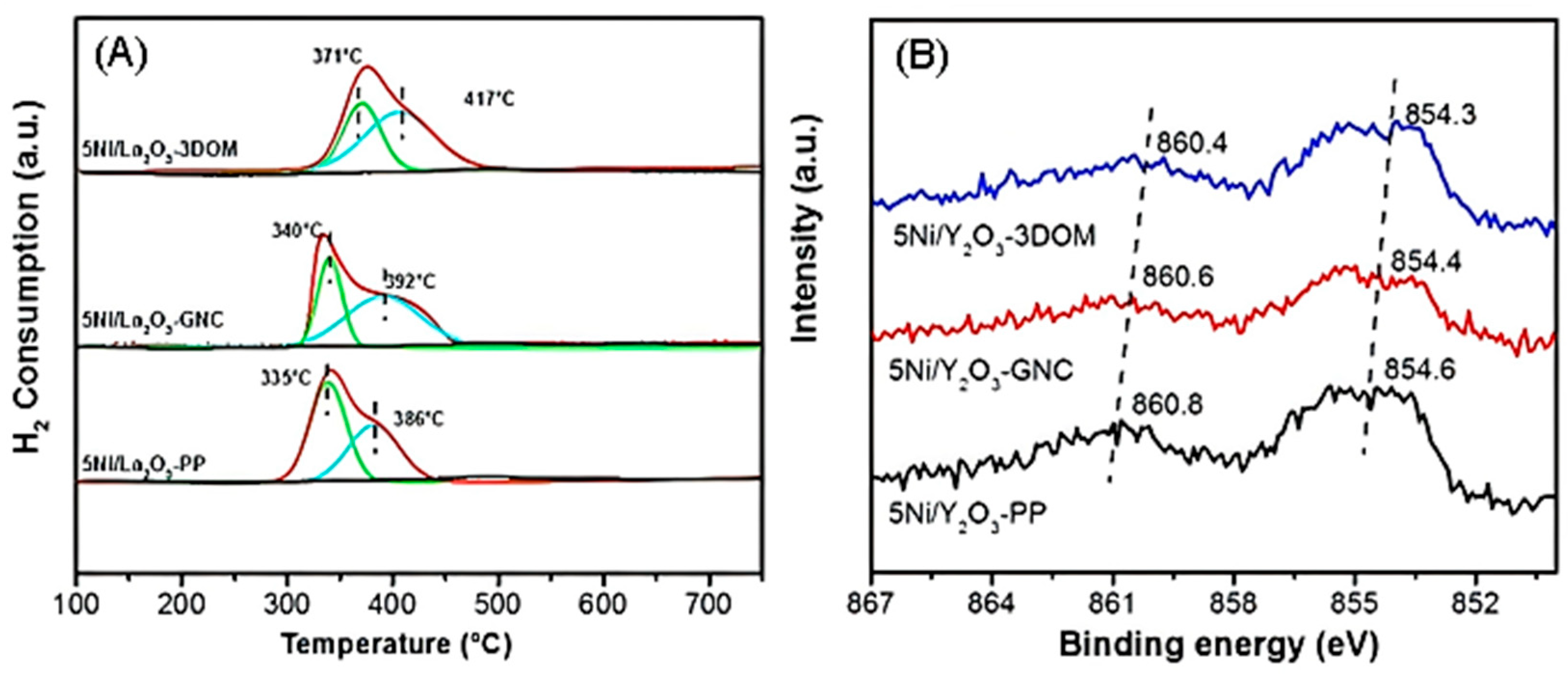
Hydrogen temperature-programmed reduction (H2-TPR) tests were performed on the freshly calcined catalysts to probe their reducibility and metal–support interactions (MSI), with the profiles shown in Figure 6. For the bare La2O3 supports prepared by different methods, no significant hydrogen consumption peaks were detected over the entire temperature range up to 800 °C—this confirms their excellent redox stability under reducing conditions, attributed to their strong La-O bonds. In contrast, all Ni-loaded catalysts exhibited distinct reduction peaks, corresponding to the reduction of NiO species. The total H2 consumption, quantified by calibration with a CuO standard, yielded H/Ni molar ratios close to 1 for all catalysts, consistent with the complete reduction of Ni2+ to Ni0 (NiO + H2 → Ni + H2O).
However, the reduction profiles differed significantly among the catalysts. Typically, reduction peaks at lower temperatures are assigned to the reduction of NiO species with weak interaction with the support, while peaks at higher temperatures signify NiO species with stronger MSI with the support. The 5Ni/La2O3-3DOM catalyst displayed a distinct shift of its main reduction peaks to significantly higher temperatures compared to both 5Ni/La2O3-GNC and 5Ni/La2O3-PP. This shift suggests a stronger overall MSI for Ni species supported on the 3DOM structure. Deconvolution and integration of the TPR peaks (Table 4) further revealed that the 5Ni/La2O3-3DOM catalyst had a substantially larger proportion of total H2 consumption occurring at higher temperatures. This quantitatively demonstrates that a greater fraction of NiO species in the 5Ni/La2O3-3DOM catalyst are engaged in stronger interactions with the La2O3-3DOM support [33,34,35].
The stronger MSI inferred from the H2-TPR profiles (higher reduction temperature, larger high-temperature peak area) for the 5Ni/La2O3-3DOM catalyst is consistent with its smaller observed Ni crystallite size after reduction (Table 2). This agreement supports the concept that stronger MSI enhances the anchoring of Ni species, inhibiting their aggregation during reduction and leading to higher dispersion and smaller metallic Ni particles.
X-ray photoelectron spectroscopy (XPS) was employed to investigate the surface chemical states and potential electronic interactions between Ni species (predominantly Ni2+ in the calcined state) and the La2O3 support. The Ni 2p core-level spectra are shown in Figure 7: peaks centered near 854.6 eV (Ni 2p3/2) and 860.8 eV (Ni 2p1/2), accompanied by their characteristic satellite features. The binding energies of all XPS spectra were charge-corrected using the C 1s peak of adventitious carbon on the sample surface (binding energy = 284.8 eV) as an internal standard—this is a conventional reference for correcting surface charge effects in XPS analysis of catalytic materials, ensuring the accuracy of Ni 2p and La 3d binding energy data.
A detailed comparison reveals distinct binding energy shifts. Relative to the precipitation-prepared 5Ni/La2O3-PP, the Ni 2p3/2 peak shifted to lower binding energies by approximately 0.5 eV for 5Ni/La2O3-GNC and 1.2 eV for 5Ni/La2O3-3DOM; this shift to lower BE indicates an increase in the electron density around Ni atoms in GNC-supported and 3DOM-supported catalysts. Conversely, the La 3d5/2 peak shifted to higher binding energies by approximately 0.3 eV (5Ni/La2O3-GNC) and 0.8 eV (5Ni/La2O3-3DOM) relative to 5Ni/La2O3-PP, suggesting a modified electronic environment of La atoms, likely induced by interaction with supported Ni species.
These observed binding energy shifts, particularly the more pronounced shifts for the 5Ni/La2O3-3DOM catalyst, are consistent with the H2-TPR results (Figure 7, Table 4). Together, they provide strong complementary evidence that the synthesis method of the La2O3 support significantly influences the strength of the Ni-support interaction, with the 3DOM structure (5Ni/La2O3-3DOM) inducing the strongest interaction.
Ni dispersion and metallic Ni surface area were both calculated via H2-TPD using a H/Ni stoichiometry of 1:1, with the following assumptions: spherical Ni particles, complete reduction of Ni2+ to Ni0, and H2 adsorption corrected by blank support tests. The calculation formulas are as follows: metallic Ni surface area (SNi) = (H2 desorption amount × 6.02 × 1023 × 0.064 nm2)/catalyst mass; Ni dispersion (D%) = (2 × H2 desorption amount)/total molar amount of Ni in the catalyst × 100% (Table 5). Data uncertainty originates from H2-TPD integration (±5%), XRD Scherrer error (±10%), and Ni loading (±3%); the final results are presented as exemplified by 5Ni/La2O3-3DOM, which has a dispersion of 4.9 ± 0.4% and a metallic Ni surface area of 2.0 ± 0.2 m2·g−1.
Based on the cross-sectional area of one surface Ni atom, 8.24 × 10⁻²⁰ m2, 0.5%Pt/Al2O3 (D = 34.5%) as the standard. Calculated via H2-TPD (H/Ni = 1:1), assuming spherical Ni, complete reduction, and blank correction; uncertainty derived from integration/XRD/loading errors.
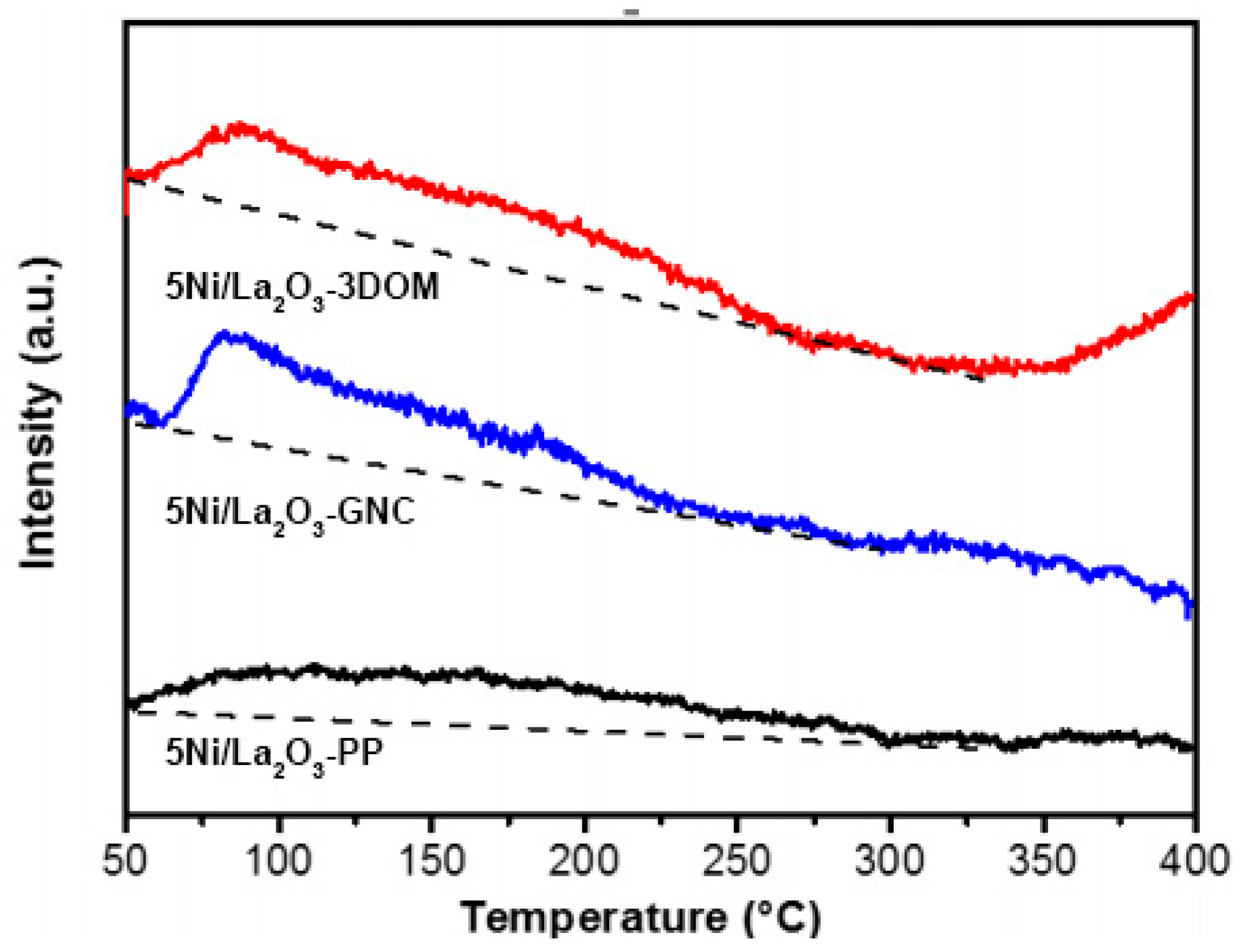
CO2-TPD characterization was performed on the reduced catalysts to probe their CO2 adsorption capacity and surface basicity. In the DRM reaction, basic sites facilitate CO2 adsorption and activation, enhancing reaction kinetics. Furthermore, the active oxygen species generated from activated CO2 can aid in removing carbon deposits, thereby improving catalyst stability [36,37,38]. As shown in Figure 8A, the CO2 desorption profiles reveal distinct regions: peaks below 200 °C are assigned to CO2 desorption from weak basic sites, peaks between 200-550 °C correspond to moderately strong basic sites, and peaks above 550 °C are attributed to strong basic sites. Moderately strong basic sites are considered particularly favorable for promoting the DRM reaction. Notably, the catalyst with the 3DOM structure (5Ni/La2O3-3DOM) exhibits significantly larger CO2 desorption peaks compared to the catalyst prepared by precipitation (5Ni/La2O3-PP). Quantitative analysis of the peak areas (Table 6) confirms that the amount of CO2 desorbed from moderately strong basic sites follows the order: 5Ni/La2O3-3DOM > 5Ni/La2O3-GNC > 5Ni/La2O3-PP. This indicates that the 3DOM-structured catalyst possesses a superior capacity for CO2 adsorption and activation. Combined with its demonstrated high activity, stability, and low carbon deposition, this enhanced CO2 adsorption/activation capability is consistent with the superior anti-coking performance observed for the 5Ni/La2O3-3DOM catalyst.
Further insight into the nature and abundance of surface oxygen species was gained through O2-TPD characterization of the reduced catalysts. As shown in Figure 8B, the O2 desorption profiles exhibit distinct peaks categorized based on desorption temperature: α-peak (attributed to weakly adsorbed oxygen), β-peak (associated with strongly adsorbed oxygen), and lattice oxygen (Olatt) evolution at higher temperatures. Quantitative analysis of the O2 desorption peak areas (Table 6) reveals that the total amount of desorbed oxygen follows the order: 5Ni/La2O3-3DOM > 5Ni/La2O3-GNC > 5Ni/La2O3-PP. This indicates that the 5Ni/La2O3-3DOM catalyst possesses the highest abundance of surface oxygen species, particularly the reactive adsorbed forms (α and β oxygen). Such abundant reactive oxygen species are known to facilitate the oxidation and removal of carbonaceous deposits. This enhanced oxygen mobility and availability correlate well with the demonstrated superior anti-coking performance of the 5Ni/La2O3-3DOM catalyst, as evidenced by its lower carbon accumulation and stable activity during long-term testing.
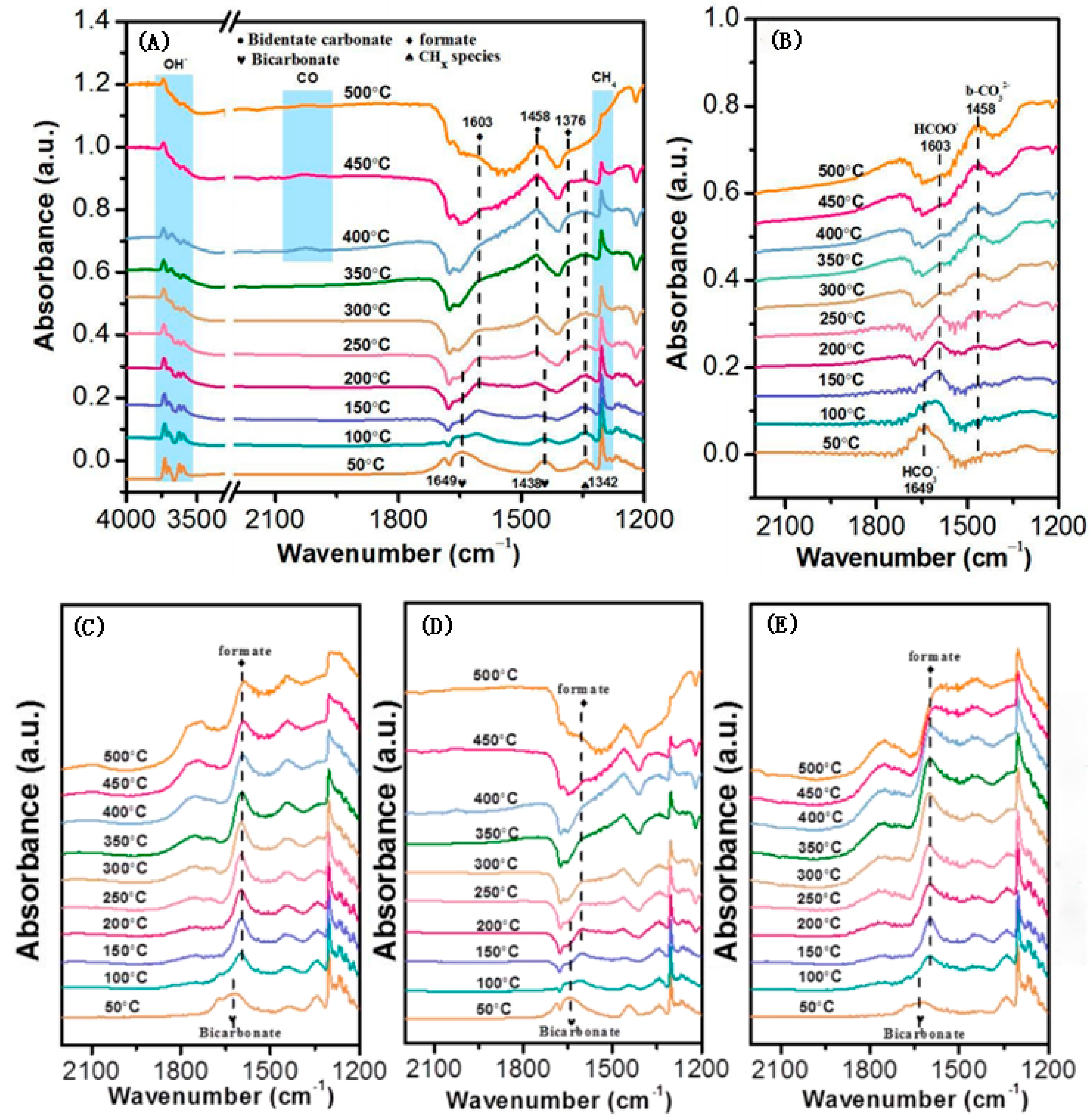
To investigate the possible reaction intermediates in methane dry reforming (DRM), in situ DRIFTs characterizations were performed on the best-performing reduced 5Ni/La2O3-3DOM catalyst under a CH4/CO2 atmosphere. As shown in Figure 9A, surface bicarbonate (HCO3*) species (peaks at 1649 and 1438 cm−1) are detected on the catalyst surface at low temperatures. With increasing temperature, the HCO3* bands gradually weaken—indicating that HCO3* is consumed and acts as an active intermediate in the DRM reaction [39]. When the temperature reaches 200 °C, the HCO3* bands disappear, and new bands emerge at 1376 and 1603 cm−1 (assigned to formate (HCOO*) species) concurrently. Upon further heating to 400 °C, a distinct CO band appears, and the HCOO* band reaches its maximum intensity; subsequently, as the temperature continues to rise, both the HCOO* and CO bands decrease simultaneously. The identical temperature-dependent behavior of the HCOO* and CO bands confirms that HCOO* serves as an active intermediate that converts into CO [40,41]. Figure 9B shows results obtained under identical conditions but with only CO2 introduced: bidentate carbonate (b-CO32−) species gradually accumulate at elevated temperatures, while bicarbonate is transformed into formate and then disappears. This suggests that bidentate carbonates are more readily formed at higher temperatures rather than functioning as reaction intermediates [42].
Figure 9C–E present temperature-dependent in situ infrared spectra of the 5Ni/La2O3-3DOM, 5Ni/La2O3-GNC, and 5Ni/La2O3-PP catalysts, respectively, under identical experimental conditions. Notably, the evolution of intermediate species during DRM follows the same general pathway across all three catalysts—bicarbonate progressively converts into formate—indicating that the same DRM reaction mechanism operates on each catalyst. However, a clear difference in formate consumption rates is observed: a small amount of formate persists on 5Ni/La2O3-3DOM at 500 °C, whereas almost no formate is detected on the other two catalysts at this temperature. These findings demonstrate that the three-dimensionally ordered macroporous La2O3-3DOM support significantly accelerates formate conversion compared with the other supports. Thus, the 3DOM structure enhances DRM activity by promoting the rapid transformation of formate intermediates.

3. Materials and Methods

3.1. Catalyst Preparation

Polymethyl methacrylate (PMMA) hard templates were prepared using the constant temperature suspension film method. A three-neck flask (3000 mL) was used, with the left port sealed with a stopper for feeding materials during the reaction (opened when needed and closed again after adding the materials); the middle port was connected to a condenser for condensation water; the right port was for nitrogen gas, with the tube extending below the reaction liquid surface, and the nitrogen flow rate was set at 100 mL·min−1. A water bath was used to heat the mixture while stirring continuously (water bath temperature 80 °C; stirring speed 300 rpm). Nitrogen was continuously introduced at 80 °C and 300 rpm, and the setup was checked for leaks, with the purging time set for 30 min to remove air from the setup. Subsequently, 114 mL of methyl methacrylate (MMA) was added, and after continuous stirring at 80 °C for 30 min, a solution made of 0.4 g of K2S2O8 and 5 mL of water was added. The setup was constantly checked for leaks, and after stirring for 1 h, the emulsion was poured into 1500 mL of deionized water and continuously stirred with a glass rod until it became completely clear, then left to stand overnight in an ice bath. The prepared PMMA emulsion was centrifuged at 5000 rpm for 50 min to remove impurity ions. After centrifugation, the supernatant was discarded, and the solid layer was taken out. The solid layer was then mixed with 20 mL of deionized water, and the solid layer on the walls of the tube was scraped off with a spatula, followed by ultrasonication for 50 min. After ultrasonication, the mixture was placed in a water bath at 80 °C to evaporate the water, and after approximately 3 h, PMMA was formed, which was visible as green and pink blocky bodies.
The La2O3-3DOM support was prepared using polyethylene–polypropylene glycol (PEG-PPG-PEG, F127) as a soft template and PMMA as a hard template. The preparation steps are as follows: 10 mmol of La(NO3)3·6H2O precursor was dissolved in a 10 g ethanol aqueous solution (with an ethanol content of 40%). After stirring until the solution became clear, 1 g of F127 was added and stirred until completely dissolved. Once the solution was clear, 4 g of PMMA hard template was added and allowed to soak overnight. The sample was then filtered, and the resulting solid was placed in a drying oven at 55 °C for 48 h. Subsequently, the obtained solid was placed in a tubular furnace, where it was heated from room temperature to 300 °C at a rate of 1 °C·min−1 under a nitrogen atmosphere and held at this temperature for 2.5 h. After cooling, the atmosphere was switched to air, and the temperature was increased to 300 °C at a rate of 1 °C·min−1, held for 2 h, and then increased to 700 °C at the same rate, where it was held for 4 h. Finally, the La2O3-3DOM support was obtained.
The co-precipitation method was employed to prepare the La2O3 support. Specifically, La(NO3)3·6H2O was dissolved in 10 mL of deionized water and stirred until the solution was clear. Subsequently, a certain amount of ammonia water (25–28%) was added to adjust the solution pH to approximately 9. After aging for 4 h, the resulting white turbid liquid was filtered and washed with deionized water until the filtrate TDS was less than 20 ppm. The sample was then dried in an oven at 110 °C for 12 h. Finally, after grinding, it was calcined in a muffle furnace at 750 °C for 3 h to obtain the La2O3 support.
The glycine combustion method was used to prepare the La2O3 support. A mixture of 8.66 g of lanthanum nitrate hexahydrate and 1.50 g of glycine was dissolved in water and stirred in a 40 °C water bath until clear. After clarification, the solution was heated and stirred in an 80 °C water bath until a gelatinous substance was formed. The gelatinous substance was then ignited in a combustion furnace at 280 °C, resulting in a white powder. Finally, the white powder was calcined in a muffle furnace at 750 °C for 3 h to produce the white La2O3 powder, denoted as the La2O3 support.

3.2. Activity Evaluation

In a fixed-bed reactor with a diameter of 6 mm, 50 mg (40–60 mesh) of catalyst is added. The catalyst is then tested for DRM reaction performance under atmospheric pressure. The catalyst is first reduced under conditions of 30 mL/min, 10% H2/Ar at 600 °C for 2 h. After reduction, it is tested for DRM reaction performance under conditions of a gas mixture with a CH4 to CO2 ratio of 1:1, at a GHSV of 36,000 mL·gcat−1·h−1, and a temperature range of 600–800 °C. The catalyst is then tested for activity under the same conditions. The molecular sieve used in the gas chromatograph column is a TDX-01 columnar type, and the reaction products are analyzed using a GC7900 gas chromatograph. The carrier gas is Ar, with an oven temperature of 110 °C, and a TCD detector temperature of 120 °C. The detector flow rate is 60 mA. The conversion rate, selectivity, and H2/CO ratio are calculated using the following formulas:
Methane conversion rate:
X C H 4   =   ( n C H 4 , i n n C H 4 , o u t ) n C H 4 , i n × 100 %
Carbon dioxide conversion rate:
X C O 2   =   ( n C O 2 , i n n C O 2 , o u t ) n C O 2 , i n × 100 %
Hydrogen selectivity:
S H 2   =   ( n H 2 , o u t ) 2 × ( n C H 4 , i n n C H 4 , o u t ) × 100 %
Hydrogen yield:
Y H 2   =   X C H 4 × S H 2 = n H 2 , o u t 2 × n C H 4 , i n × 100 %
The variables nCH4,in, nCO2,in, nH2,out, and nCO2,out represent the amounts of the corresponding components. The calculation method is based on the carbon balance, and the results are normalized by the stoichiometric coefficients. At a temperature range of 450–500 °C, the conversion rate of methane is controlled below 10%, and the reaction rate is determined by changing the amount of catalyst.

4. Conclusions

This study employed precipitation, glycine–nitrate combustion, and colloidal crystal templating methods to synthesize three distinct La2O3 supports for Ni-based catalysts in methane dry reforming (DRM). Structural characterization revealed that the colloidal crystal templating approach successfully produced La2O3-3DOM supports with highly ordered, uniform three-dimensional macroporous architectures—contrasting with the irregular morphologies obtained via precipitation and glycine–nitrate combustion methods. XRD and N2 physisorption analyses further demonstrated that 3DOM-structured La2O3 possesses the smallest crystallite size and the largest specific surface area among the three supports.
Catalytic evaluation established the following performance order for DRM (in terms of both activity and stability): 5Ni/La2O3-3DOM > 5Ni/La2O3-GNC > 5Ni/La2O3-PP. Complementary TGA-DSC and Raman spectroscopy results confirmed the superior coke resistance of the 5Ni/La2O3-3DOM catalyst. Mechanistic insights from H2-TPR and XPS revealed the strongest metal–support interaction (MSI) in the 5Ni/La2O3-3DOM catalyst, which effectively anchors Ni particles and suppresses sintering. Consistent with this, XRD and H2-TPD analyses showed that this catalyst exhibits the smallest Ni crystallites and highest Ni dispersion—critical factors for enhancing DRM performance.
Furthermore, CO2-TPD and O2-TPD characterizations revealed that the 3DOM-structured catalyst had the highest density of moderately strong basic sites (26.5 μmol/g) for CO2 adsorption and activation, as well as the most abundant reactive oxygen species (total O2 desorption amount: 38.0 μmol·g−1). These properties synergistically contributed to the catalyst’s exceptional carbon elimination capability and long-term catalytic durability.
In situ DRIFTS characterizations provided evidence for the evolution of reaction intermediates: bicarbonate (HCO3*) species were detected at low temperatures and gradually converted to formate (HCOO*) with increasing temperature, and CO was subsequently generated. On this basis, the authors propose that HCO3* → HCOO* → CO is a potential operative pathway for the DRM reaction over the studied catalysts. Among the three catalysts, the 3DOM-structured 5Ni/La2O3 catalyst accelerated the final conversion of HCOO* to CO; this faster consumption of surface formate is tentatively associated with its superior DRM activity, though the exact correlation still requires further validation from kinetic data. Notably, the current mechanistic inference relies on the qualitative evolution of DRIFTS intermediates; future studies should include time-resolved quantification of intermediates, control experiments, and kinetic measurements to fully confirm the link between formate consumption and catalytic rate enhancements.

Author Contributions

Conceptualization: S.L. and A.D.; methodology: S.L.; software, S.L.; validation: S.L., A.D., and W.Z.; formal analysis: S.L.; investigation: S.L.; resources: Z.X.; data curation: S.L.; writing—original draft preparation: S.L.; writing—review and editing, A.D.; visualization, Y.X.; supervision: H.Z. and M.P.P. All authors have read and agreed to the published version of the manuscript.

Funding

This research received no external funding.

Institutional Review Board Statement

Not applicable. This study focuses on the synthesis of catalysts and the evaluation of their performance in methane dry reforming, which does not involve humans or animals; thus, no ethical approval was required.

Informed Consent Statement

Not applicable. This study does not involve human subjects, so no informed consent was needed.

Data Availability Statement

The data supporting the findings of this study are available from the corresponding author upon reasonable request. The raw data include catalyst synthesis records, activity test results (conversion rates, selectivity, etc.), characterization data (XRD, SEM, N2 adsorption–desorption, TGA-DSC, Raman, H2-TPR, CO2-TPD, O2-TPD, XPS, and in situ DRIFTS), and related calculation sheets. All data have been processed and analyzed as presented in the manuscript.

Acknowledgments

The authors would like to thank the analytical testing center of Beijing Normal University for providing access to characterization equipment (such as XRD, SEM, and XPS) and technical support during sample testing. Beijing Qinghuan Energy Technology Co., Ltd. is acknowledged for supplying partial experimental materials and site support.

Conflicts of Interest

Authors Wenchuan Zhang and Zhongdong Xie were employed by the company Beijing Qinghuan Energy Technology Co., Ltd. The remaining authors declare that the research was conducted in the absence of any commercial or financial relationships that could be construed as a potential conflict of interest.

References

  1. Fan, Z.; Weng, W.; Zhou, J.; Gu, D.; Xiao, W. Catalytic decomposition of methane to produce hydrogen: A review. J. Energy Chem. 2021, 58, 415–430. [Google Scholar] [CrossRef]
  2. Pakhare, D.; Spivey, J. A review of dry (CO2) reforming of methane over noble metal catalysts. Chem. Soc. Rev. 2014, 22, 7813–7837. [Google Scholar] [CrossRef]
  3. Laan, J. Negative-emissions hydrogen energy. Nat. Clim. Change 2018, 8, 560–561. [Google Scholar]
  4. Qi, J.; Zhang, W.; Cao, R. Solar-to-Hydrogen Energy Conversion Based on Water Splitting. Adv. Energy Mater. 2017, 8, 1701620. [Google Scholar] [CrossRef]
  5. Meiliefiana, M.; Nakayashiki, T.; Yamamoto, E.; Hayashi, K.; Ohtani, M.; Kobiro, K. One-Step Solvothermal Synthesis of Ni Nanoparticle Catalysts Embedded in ZrO2 Porous Spheres to Suppress Carbon Deposition in Low-Temperature Dry Reforming of Methane. Nanoscale Res. Lett. 2022, 17, 47. [Google Scholar] [CrossRef]
  6. Bahari, M.B.; Mamat, C.R.; Jalil, A.A.; Hassan, N.S.; Hatta, A.H.; Alhassan, M.; Aziz, M.A.; Le, V.G.; Siang, T.J.; Timmiati, S.N. Mitigating deactivation in dry methane reforming by lanthanum catalysts for enhanced hydrogen production: A review. Int. J. Hydrogen Energy 2025, 104, 426–443. [Google Scholar] [CrossRef]
  7. Liu, H.; Swirk, K.; Galvez, M.E.; da Costa, P. Nickel Supported Modified Ceria Zirconia Lanthanum/Praseodymium/Yttrium Oxides Catalysts for Syngas Production through Dry Methane Reforming. In Proceedings of the 10th International Conference on Processing and Manufacturing of Advanced Materials Processing, Fabrication, Properties, Applications (THERMEC), Cite Sci Paris, Paris, France, 9–13 July 2018; Volume 941, pp. 2214–2219. [Google Scholar]
  8. Zhang, J.-C.; Ge, B.-H.; Liu, T.-F.; Yang, Y.-Z.; Li, B.; Li, W.-Z. Robust Ruthenium-Saving Catalyst for HighTemperature Carbon Dioxide Reforming of Methane. ACS Catal. 2020, 10, 783–791. [Google Scholar] [CrossRef]
  9. Su, B.; Wang, Y.; Xu, Z.; Han, W.; Jin, H.; Wang, H. Novel ways for hydrogen production based on methane steam and dry reforming integrated with carbon capture. Energy Convers. Manag. 2022, 270, 116199. [Google Scholar] [CrossRef]
  10. Alhassan, M.; Jalil, A.A.; Nabgan, W.; Hamid, M.Y.S.; Bahari, M.B.; Ikram, M. Bibliometric studies and impediments to valorization of dry reforming of methane for hydrogen pro-duction. Fuel 2022, 328, 125240. [Google Scholar] [CrossRef]
  11. Kumar, R.; Kumar, A.; Pal, A. Overview of hydrogen production from biogas reforming: Technological advancement. Int. J. Hydrogen Energy 2022, 47, 34831–34855. [Google Scholar] [CrossRef]
  12. Das, S.; Ashok, J.; Bian, Z.; Dewangan, N.; Wai, M.; Du, Y.; Borgna, A.; Hidajat, K.; Kawi, S. Silica–Ceria sandwiched Ni core–shell catalyst for low temperature dry reforming of biogas: Coke resistance and mechanistic insights. Appl. Catal. B Environ. 2018, 230, 220–236. [Google Scholar] [CrossRef]
  13. Ou, Z.; Zhang, Z.; Qin, C.; Xia, H.; Deng, T.; Niu, J.; Ran, J.; Wu, C. Highly active and stable Ni/perovskite catalysts in steam methane reforming for hydrogen production. Sustain. Energy Fuels 2021, 5, 1845–1856. [Google Scholar] [CrossRef]
  14. Choudhary, V.; Rajput, A.; Prabhakar, B.J.C. Energy efficient methane-to-syngas conversion with low H2/CO ratio by simultaneous catalytic reactions of methane with carbon dioxide and oxygen. Catal. Lett. 1995, 32, 391–396. [Google Scholar] [CrossRef]
  15. Li, L.; Chen, J.; Zhang, Q.; Yang, Z.; Sun, Y.; Zou, G. Methane dry reforming over activated carbon supported Ni catalysts prepared by solid phase synthesis. J. Clean. Prod. 2020, 274, 122256. [Google Scholar] [CrossRef]
  16. Fan, M.-S.; Abdullah, A.Z.; Bhatia, S. Catalytic Technology for Carbon Dioxide Reforming of Methane to Synthesis Gas. ChemCatChem 2009, 1, 192–208. [Google Scholar] [CrossRef]
  17. Li, M.; van Veen, A.C. Coupled reforming of methane to syngas (2H2-CO) over Mg-Al oxide supported Ni catalyst. Appl. Catal. A Gen. 2017, 550, 176–183. [Google Scholar] [CrossRef]
  18. Tavasoli, A.; Gouda, A.; Zähringer, T.; Li, Y.F.; Quaid, H.; Perez, C.J.V.; Song, R.; Sain, M.; Ozin, G. Enhanced hybrid photocatalytic dry reforming using a phosphated Ni-CeO2 nanorod heterostructure. Nat. Commun. 2023, 14, 1435. [Google Scholar] [CrossRef]
  19. Bernal, S.; Blanco, E.; Botana, K.J.; Garcia, R.; Ramirez, F.; Rodriguez-Izquierdo, J. Preparation of some rare earth oxide supported rhodium catalysts: Study of the supports. Mater. Chem. Phys. 1987, 17, 433–443. [Google Scholar] [CrossRef]
  20. Zhang, Y.; Jung, I.-H. Critical evaluation of thermodynamic properties of rare earth sesquioxides (RE = La, Ce, Pr, Nd, Pm, Sm, Eu, Gd, Tb, Dy, Ho, Er, Tm, Yb, Lu, Sc and Y). Calphad 2017, 58, 169–203. [Google Scholar] [CrossRef]
  21. Sutthiumporn, K.; Kawi, S. Promotional effect of alkaline earth over Ni-La2O3 catalyst for CO2 reforming of CH4: Role of surface oxygen species on H2 production and carbon suppression. Int. J. Hydrogen Energy 2011, 36, 14435–14446. [Google Scholar] [CrossRef]
  22. Li, Y.H.; Zeng, D.M.; Huang, K.L. Preparation and Applications of Ordered Macroporous Materials. Prog. Chem. 2008, 20, 245–252. [Google Scholar]
  23. Yu, J.Y.; Li, Q.; Ma, X.H.; Sun, X.D. Preparation and Applications of Three-Dimensionally Ordered Macroporous Materials. Mater. Rev. 2008, 20, 21–24. [Google Scholar]
  24. Zhang, C.; Zhao, P.; Liu, S.; Yu, K. Three-dimensionally ordered macroporous perovskite materials for environmental applications. Chin. J. Catal. 2019, 40, 1324–1338. [Google Scholar] [CrossRef]
  25. Jiang, Y.; Liu, T.; Gao, W.; Ge, H.; Yang, Z.; Lin, R.; Wang, X. Three-dimensionally ordered macroporous Ce-W-Nb oxide catalysts for selective catalytic reduction of NOx with NH3. Chem. Eng. J. 2022, 433, 134576. [Google Scholar] [CrossRef]
  26. Zhang, Y.; Lei, Z.; Li, J.; Lu, S. A new route to three-dimensionally well-ordered macroporous rare-earth oxides. New J. Chem. 2001, 25, 1118–1120. [Google Scholar] [CrossRef]
  27. Silva, R.S.; Cunha, F.; Barrozo, P. Raman spectroscopy of the Al-doping induced structural phase transition in LaCrO3 perovskite. Solid State Commun. 2021, 333, 114346. [Google Scholar] [CrossRef]
  28. Triyono, D.; Hanifah, U.; Laysandra, H. Structural and optical properties of Mg-substituted LaFeO3 nanoparticles prepared by a sol-gel method. Results Phys. 2020, 16, 102995. [Google Scholar] [CrossRef]
  29. Dou, J.; Zhang, R.; Hao, X.; Bao, Z.; Wu, T.; Wang, B.; Yu, F. Sandwiched SiO2@Ni@ZrO2 as a coke resistant nanocatalyst for dry reforming of methane. Appl. Catal. B Environ. 2019, 254, 612–623. [Google Scholar] [CrossRef]
  30. Kathiraser, Y.; Oemar, U.; Saw, E.T.; Li, Z.; Kawi, S. Kinetic and mechanistic aspects for CO2 reforming of methane over Ni based catalysts. Chem. Eng. J. 2015, 278, 62–78. [Google Scholar] [CrossRef]
  31. Qian, L.; Ma, Z.; Ren, Y.; Shi, H.; Yue, B.; Feng, S.; Shen, J.; Xie, S. Investigation of La promotion mechanism on Ni/SBA-15 catalysts in CH4 reforming with CO2. Fuel 2014, 122, 47–53. [Google Scholar] [CrossRef]
  32. Chen, W.; Zhao, G.; Xue, Q.; Chen, L.; Lu, Y. High carbon-resistance Ni/CeAlO3-Al2O3 catalyst for CH4/CO2 reforming. Appl. Catal. B Environ. 2013, 136–137, 260–268. [Google Scholar] [CrossRef]
  33. Egawa, C. Methane dry reforming reaction on Ru(001) surfaces. J. Catal. 2018, 358, 35–42. [Google Scholar] [CrossRef]
  34. Hou, W.; Wang, Y.; Bai, Y.; Sun, W.; Yuan, W.; Zheng, L.; Han, X.; Zhou, L. Carbon dioxide reforming of methane over Ni/Mg0.4Al0.4- La0.1Zr0.1(O) catalyst prepared by recombination sol-gel method. Int. J. Hydrogen Energy 2017, 42, 16459–16475. [Google Scholar] [CrossRef]
  35. Wang, Y.; Zheng, Y.; Wang, Y.; Li, K.; Wang, Y.; Jiang, L.; Zhu, X.; Wei, Y.; Wang, H. Syngas production modified by oxygen vacancies over CeO2-ZrO2-CuO oxygen carrier via chemical looping reforming of methane. Appl. Surf. Sci. 2019, 481, 151–160. [Google Scholar] [CrossRef]
  36. Bhattar, S.; Abedin, M.A.; Kanitkar, S.; Spivey, J.J. A review on dry reforming of methane over perovskite derived catalysts. Catal. Today 2021, 365, 2–23. [Google Scholar] [CrossRef]
  37. Xu, J.; Xi, R.; Zhang, Z.; Xu, X.; Fang, X.; Wang, X. Promoting the surface active sites of defect BaSnO3 perovskite with BaBr2 for the oxidative coupling of methane. Catal. Today 2020, 374, 29–37. [Google Scholar] [CrossRef]
  38. Long, R.Q.; Wan, H.L. In situ confocal microprobe Ramanspectroscopy study of CeO2/BaF2 catalyst for theoxidative coupling of methane. J. Chem. Soc. Faraday Trans. 1997, 93, 355–358. [Google Scholar] [CrossRef]
  39. Abd Ghani, N.A.; Azapour, A.; Syed Muhammad, A.F.; Ramli, N.M.; Vo, D.-V.N.; Abdullah, B. Dry reforming of methane for hydrogen production over NiCo catalysts: Effect of NbZr promoters. Int. J. Hydrogen Energy 2018, 44, 20881–20888. [Google Scholar] [CrossRef]
  40. Zhang, S.; Ying, M.; Yu, J.; Zhan, W.; Wang, L.; Guo, Y.; Guo, Y. NixAl1O2-δ mesoporous catalysts for dry reforming of 75 methane: The special role of NiAl2O4 spinel phase and its reaction mechanism. Appl. Catal. B Environ. 2021, 291, 120047. [Google Scholar] [CrossRef]
  41. Cao, T.; You, R.; Zhang, X.; Chen, S.; Li, D.; Zhang, Z.; Huang, W. An in situ DRIFTS mechanistic study of CeO2-catalyzed acetylene semihydrogenation reaction. Phys. Chem. Chem. Phys. 2018, 20, 9659–9670. [Google Scholar] [CrossRef]
  42. Lavoie, J.-M. Review on dry reforming of methane, a potentially more environmentally-friendly approach to the increasing natural gas exploitation. Front. Chem. 2014, 2, 81. [Google Scholar] [CrossRef] [PubMed]
Figure 1. SEM micrographs: (A) PMMA hard template; (B) La2O3-3DOM support; (C) La2O3-PP support; (D) La2O3-GNC support.
Catalysts 15 00992 g001
Figure 2. (A) XRD patterns and (B) N2 adsorption–desorption isotherms of the supports.
Catalysts 15 00992 g002
Figure 3. Catalyst DRM reaction activity test: (A) Methane conversion rate; (B) Carbon dioxide conversion rate; (C) H2 yield. Reaction conditions: CH4:CO2 = 1:1, GHSV = 36,000 mL·h−1·gcat−1, 1 atm. Catalyst DRM reaction stability test: (D) Methane conversion rate; (E) Carbon dioxide conversion rate; (F) H2 yield.
Catalysts 15 00992 g003
Figure 4. XRD patterns of the catalysts: (A) Fresh calcined catalysts; (B) reduced catalysts; (C) used catalysts.
Catalysts 15 00992 g004
Figure 5. Carbon deposition analysis of used catalysts: (A) Raman spectra; (B) TGA-DSC curves.
Catalysts 15 00992 g005
Figure 6. (A) H2-TPR profiles of fresh catalysts. (B) XPS spectra of fresh catalysts.
Catalysts 15 00992 g006
Figure 7. H2-TPD profiles of reduced catalysts.
Catalysts 15 00992 g007
Figure 8. (A) CO2-TPD profiles of various reduced catalysts. (B) O2-TPD profiles of various freshly calcined catalysts.
Catalysts 15 00992 g008
Figure 9. In situ DRIFTS spectra of the reduced 5Ni/La2O3-3DOM catalyst under a reaction gas mixture at different temperatures; (A) CH4:CO2 = 1:1; (B) only to CO2. In situ DRIFTS spectra of various reduced catalysts under a reaction gas mixture of CH4:CO2 = 1:1 at different temperatures: (C) 5Ni/La2O3-3DOM, (D) 5Ni/La2O3-GNC, and (E) 5Ni/La2O3-PP.
Catalysts 15 00992 g009
Table 1. Structural Characteristics of Various Carriers.
CatalystsSurface Area (m2/g) [a]Crystallite Size (nm) [b]Mesopore (cm3/g)Macropore (cm3/g)Total (cm3/g)
La2O3-PP4113.30.080.020.10
La2O3-GNC5012.80.130.030.16
La2O3-3DOM6210.90.190.100.29
[a] Calculated using the BET method; [b] calculated from XRD results.
Table 2. Structural characteristics of the catalysts before and after the reaction.
CatalystsFresh CatalystsReduced CatalystsUsed Catalysts
Surface Area (m2/g) [b]NiO Crystallite Size (nm) [a]Surface Area (m2/g)Ni Crystallite Size (nm)Surface Area (m2/g)Ni Crystallite Size (nm)
5Ni/La2O3-PP3812.83613.83123.5
5Ni/La2O3-GNC4611.54311.94019.5
5Ni/La2O3-3DOM6110.95811.25714.0
[a] Calculated from XRD results; [b] determined by means of N2—BET.
Table 3. Quantitative results from Raman and TGA-DSC analyses.
CatalystsCarbon Deposition Amount (%)Coking Rate
(mgC·g−1·h−1) [a]
IG/IDTotal Weight Loss (300–800 °C, %)
5Ni/La2O3-PP12.52.51.3015.2
5Ni/La2O3-GNC9.52.10.8812.1
5Ni/La2O3-3DOM5.21.10.647.8
[a] From TGA, the temperature range is from 300 °C to 800 °C.
Table 4. Quantitative results of H2-TPR for fresh catalysts.
CatalystsH2 Consumption (mmol·g−1)
α Peakβ PeakTotalH/Ni
5Ni/La2O3-PP0.470.390.861.02
5Ni/La2O3-GNC0.390.480.871.05
5Ni/La2O3-3DOM0.330.560.891.06
Table 5. Specific surface area and dispersion of Ni on the surface of reduced catalysts.
CatalystsH2 Desorption Amount (μmol·g−1)Metallic Ni Surface Area (m2·g−1·cat−1)Metallic Ni Surface Area (m2·g−1)Ni Dispersion (%)
5Ni/La2O3-PP29.4 ± 1.51.4 ± 0.129.2 ± 1.53.4 ± 0.3
5Ni/La2O3-GNC34.7 ± 1.71.7 ± 0.134.3 ± 1.74.0 ± 0.3
5Ni/La2O3-3DOM42.5 ± 2.12.0 ± 0.242.1 ± 2.14.9 ± 0.4
Table 6. CO2 and O2 desorption amounts of reduced catalysts.
CatalystsCO2 Desorption (μmol/g)Total (μmol/g)O2 Desorption (μmol·g−1)Total (μmol/g)
WeakModerateStrongα Peakβ PeakOlatt
5Ni/La2O3-PP9.321.85.236.311.22.34.618.1
5Ni/La2O3-GNC11.123.34.839.214.88.9--23.7
5Ni/La2O3-3DOM12.126.54.643.212.718.96.438.0
Disclaimer/Publisher’s Note: The statements, opinions and data contained in all publications are solely those of the individual author(s) and contributor(s) and not of MDPI and/or the editor(s). MDPI and/or the editor(s) disclaim responsibility for any injury to people or property resulting from any ideas, methods, instructions or products referred to in the content.