Abstract
The creation of multi-stimuli-sensitive composite polymer–inorganic materials is a practical scientific task. The combination of photoactive magneto-piezoelectric nanomaterials and ferroelectric polymers offers new properties that can help solve environmental and energy problems. Using the doctor blade casting method with the thermally induced phase separation (TIPS) technique, we synthesized a hybrid polymer–inorganic nanocomposite porous membrane based on polyvinylidene fluoride (PVDF) and bismuth ferrite (BiFeO3/BFO). We studied the samples using transmission and scanning electron microscopy (TEM/SEM), infrared Fourier spectroscopy (FTIR), total transmission and diffuse reflection, fluorescence microscopy, photoluminescence (PL), differential scanning calorimetry (DSC), thermogravimetric analysis (TGA), vibrating-sample magnetometer (VSM), and piezopotential measurements. Our results demonstrate that the addition of BFO increases the proportion of the polar phase from 76.2% to 93.8% due to surface ion–dipole interaction. We also found that the sample exhibits laser-induced fluorescence, with maxima at 475 and 665 nm depending on the presence of nanoparticles in the polymer matrix. Furthermore, our piezo-photocatalytic experiments showed that under the combined actions of ultrasonic treatment and UV–visible light irradiation, the reaction rate increased by factors of 68, 13, 4.2, and 1.6 compared to sonolysis, photolysis, piezocatalysis, and photocatalysis, respectively. This behavior is explained by the piezoelectric potential and the narrowing of the band gap of the composite due to the mechanical stress caused by ultrasound.
Keywords:
PVDF; BiFeO3; photocatalysis; piezocatalysis; piezophotocatalysis; PENG; ultrasound; smart materials 1. Introduction
Water pollution is one of the most widespread problems in the world, leading to serious consequences such as the loss of biodiversity, ecological degradation, and the devaluation of water resources. Therefore, it is crucial to understand the causes and effects of dye-related water pollution. The purification of water from dye pollution is essential for preserving the value of water resources and maintaining public health, making it a top priority in the field of ecology. Various methods are available for purifying water from dyes, including chemical, physical, and biological methods, adsorption, flotation, separation, photochemistry, and photocatalysis [1,2].
Advanced oxidation processes (AOPs), particularly photocatalysis (PC), are considered some of the most effective tools for decomposing aqueous organic pollutants [3,4]. This is due to the relative simplicity of the process, its low labor requirements, its cost-effectiveness, and absence of secondary pollutants resulting from complete mineralization [5,6,7].
Bismuth-containing nanomaterials are among the most promising candidates for catalyzing AOPs [8,9]. BiFeO3 (BFO) has gained increasing attention in recent years due to its multiferroic properties, magnetoelectric and ferroelectric properties, use as a narrow-gap semiconductor material with a band gap of about 2.2 eV, and potential applications in piezoelectric devices, sensors, photosensitizers, and spintronics. Its non-toxicity, economic efficiency, special crystal structure, electrical conductivity, stability, magnetism, and electro-optical properties make it particularly interesting for photocatalysis [10,11,12,13].
The high cost of separating and regenerating suspension photocatalysts is a serious problem that limits their practical applications. Additionally, the inevitable loss of nanoparticles during separation can lead to secondary environmental pollution. In this context, efforts have been made to immobilize the photocatalyst in or on supports that can be adapted to the reactor, reduce mass transfer limitations, and transfer the radiation flux to the immobilized photocatalyst. Polymer composites represent a potential alternative for meeting this need. Moreover, immobilizing the catalyst in the polymer matrix can prevent the photocorrosion of BiFeO3, which was previously reported in [14].
The use of stimulus-sensitive polymers can not only solve the problem of immobilization but also promote functionalization and increase photocatalytic activity. In recent years, the field of the contactless enhancement of photocatalysis in external fields, such as thermal, magnetic, microwave, and ultrasonic fields, has been intensively developed [15,16,17,18]. External fields may act as an additional force for a more efficient separation of photogenerated carriers. One of the most effective strategies in this direction is to create a polarization electric field through a combination of piezoelectric and photocatalytic materials to provide the driving force for the separation of photogenerated carriers [19].
One such material is polyvinylidene fluoride (PVDF) [20]. Depending on the crystallization process, this polymer itself can have piezoelectric properties due to polymorphism among the five known phases (α, β, γ, δ, and ε) with different molecular chain conformations [21]. Interest in the topic of piezophotocatalysis (photocatalysis enhanced by an external polarization electric field) on hybrid composites containing PVDF and inorganic nanoparticles began to form in the last few years [22,23,24,25,26,27,28].
Although the immobilization of catalysts in polymer matrices is a viable solution, it is widely accepted that there is a significant decrease in photocatalytic activity and selectivity due to a reduction in the active surface area to volume ratio, as well as inefficient light collection associated with a high content of inactive matrices [29,30]. As a result, photocatalytic activity must be sacrificed to improve usability. However, there are also interesting reports that contradict this view. For example, in [31], a ZnSnO3 photocatalyst film grown on glass was completely covered with PVDF. The results of the PC decomposition of MB showed that the efficiency of the PVDF-ZnSnO3 nanocomposite was higher than that of pure ZnSnO3. However, it remains unclear why the PC efficiency of the hybrid material was higher than that of a pure photocatalyst. In all their works, the authors did not take into account the role of the electronic structure of PVDF and its polarization properties, considering it only a convenient, inert substrate for a photocatalyst. The results of our previous studies have shown that in order to achieve a deeper understanding of the processes, it is necessary to consider even those nuances that may not be obvious for photocatalysis [11,32].
Composite materials based on PVDF and BFO have previously been reported [33,34,35,36,37,38,39,40,41,42,43,44,45,46,47,48]. These works revealed many aspects of the procedures for synthesizing both nanoparticles and polymer composites via various methods. It has been demonstrated that the addition of BFO promotes the repolarization of the polymer matrix from the nonpolar to the polar conformation and that the surfaces of the nanoparticles play a crucial role in this process. The structural, optical, magnetic, electrical ferroelectric, and magnetoelectric properties of the composites have been studied in detail. Many works are devoted to the possibility of practical applications of composites as energy harvesters. However, we did not find any works in which these composites were investigated as catalysts in the processes of piezo-, photo-, and piezophotocatalysis. Additionally, from an analysis of the available works, it is apparent that the method of synthesis of a polymer composite directly affects the morphology and structure of the material, and this choice depends on the intended use of the material. In our previous work, we demonstrated that a PVDF/BFO composite membrane obtained via electrospinning exhibits high piezophotocatalytic activity due to the simultaneous collection of light and mechanical energy [49].
Based on the above, and to investigate the effect of the synthesis method on the piezophotocatalytic activity of the composite, we synthesized a PVDF/BFO composite membrane using the method of thermally stimulated phase inversion.
2. Results
The composites were synthesized using BFO nanoparticles synthesized according to the method described in [11,12]. Figure 1 shows TEM images of the BFO nanoparticles.
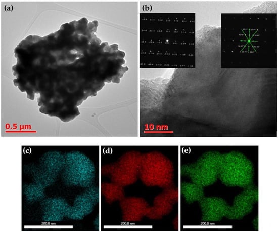
Figure 1.
(a,b) TEM images of BFO nanoparticles at various magnifications. Elemental mapping of BFO nanoparticles ((c)—Bi, (d)—Fe, (e)—O).
Figure 1a illustrates that the sample at high magnification consists of agglomerates approximately 2 μm in size, formed from nanoparticles with an average size of around 100 nm. These agglomerates may have sintered during both the high-temperature synthesis and the subsequent annealing at 600 °C. Figure 1b displays an image of a single grain at a higher resolution in which the grain boundaries are visible, and the grain size can be estimated to be approximately 60–70 nm. The grains are well-crystallized in bulk, and an amorphous phase is only observed at the edges. The inset in Figure 1b depicts a selected area electron diffraction (SAED) pattern taken from a single grain, which indicates the formation of well-formed BFO nanoparticles, with sharp diffraction spots confirming crystallization in R3c. The elemental mapping presented in Figure 1c–e demonstrates the uniformity of element distribution in the grains and the absence of impurities.
Subsequently, a membrane containing BFO nanoparticles immobilized in a PVDF matrix was fabricated. Figure 2 illustrates the surface structures and cross-sections of PVDF composites.
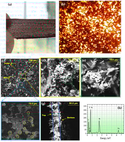
Figure 2.
(a) Photo of PVDF/BFO membrane; (b) optical microscopy image of PVDF/BFO membrane ×500; (c–e) SEM images of a PVDF/BFO composite membrane at various magnifications; (f) SEM images of the surface at low accelerating voltages; (g) SEM images of the membrane side cut; (h) EDX spectrum.
Figure 2a displays a transmission photograph of the completed membrane, revealing a network structure resulting from the BFO particle agglomeration during the membrane’s heat treatment. A closer examination of the reticulation is provided in Figure 2b, an optical micrograph at 500× magnification, where dark areas correspond to zones of fine-dispersion structural elements, potentially nanoparticles. The surface morphology of the composite at various magnifications and at high accelerating voltages on the SEM is depicted in Figure 2c–e. The high accelerating voltage permits translucence effects, with light areas representing BFO particles integrated into the polymer matrix. At higher magnifications (Figure 2c), the bone-like morphology of the powder characteristic of the combustion-synthesized powder is evident, with the surface featuring numerous pores of varying sizes. Figure 2f shows an SEM image at low accelerating voltage values of a distinct surface area where morphological polymer structural elements with spherical granular shapes are evident. A side-cut image of the composite (Figure 2g) reveals an asymmetric morphology marked by a thin and relatively dense bottom layer, a surface with eyelash-like structures, and a porous middle layer. This asymmetrical structure results from intense solvent evaporation from the bulk of the polymer during thermally stimulated phase inversion, with the image additionally indicating that the sample thickness does not exceed 100 µm.
Figure 3 presents the results of the X-ray diffraction study at room temperature.
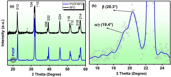
Figure 3.
(a) BFO and PVDF/BFO radiographs. (b) A fragment of the diffraction pattern of a PVDF + BFO sample identifying PVDF peaks.
The results of the X-ray diffraction studies for the BFO and PVDF/BFO samples are presented in Figure 3. The X-ray diffraction patterns show peaks near 2θ~28° which are associated with the presence of a small amount of impurity phases (Bi25FeO40 and Bi2Fe4O9, less than 3%). The average crystallite sizes, calculated from peak (012) using the Scherrer formula, were 56.3 nm. The XRD spectra of the composite confirm that the BFO structure remained unchanged. Sharp and intense BFO peaks are visible on the images, while the PVDF peak is weakly expressed, indicating a high concentration of nanoparticles. There is no evidence of structural changes in the PVDF and BFO. The fragment of the diffraction pattern (Figure 3b) shows the most intense peaks related to PVDF. According to [50], all phases of the α, β, and γ phases of PVDF have an intense peak near 20°, but the α and β phases have a set of additional peaks. The peak near 20.3° [51] refers to the β-phase of the PVDF, with the sum of the diffraction in the planes (110) and (200), while the shoulder in the region of 19.4° can correspond to both the plane (002) of the γ-phase of the PVDF and the plane (110) in the monoclinic α-phase. Thus, it can be seen that a large proportion of the electroactive phase is present in the composite sample.
To determine the quantitative content of the polar and non-polar phases, the IR-Fourier spectroscopy method is usually used. Figure 4 shows the IR absorption spectra of a pure PVDF polymer and a composite PVDF/BFO synthesized under similar conditions.
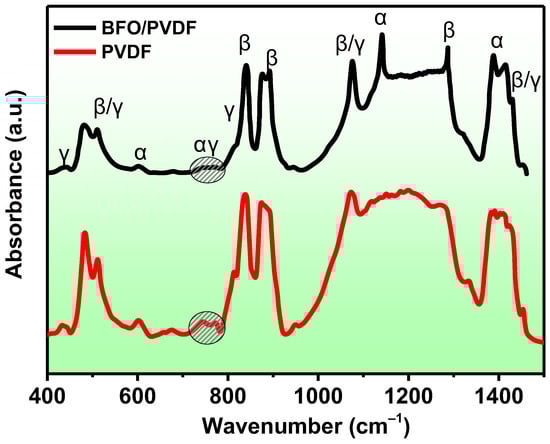
Figure 4.
FTIR spectra of pure PVDF and PVDF/BFO membranes.
The spectra of both the pure PVDF and the composite exhibit absorption bands that are characteristic of the three main α, β, and γ polymorphs of PVDF. According to [52], the characteristic bands of the α-phase are approximately at 410, 489, 532, 614, 763, 795, 854, 975, 1149, 1209, 1383, and 1423 cm–1. For the β-phase, they are at about 445, 473, and 1275 cm–1, and for the γ-phase, they are at about 431, 482, 811, and 1234 cm–1. Although peaks in the range of 837–841 and 508–512 cm–1 can appear in many different samples, the absorption for the β- and γ-phases is much stronger than for the α-phase. The peak at 840* can be used to characterize the electroactive β- and/or γ-phases, while the 763 peak is characteristic only of the non-polar phase. It can be observed from the spectra that the peak at 840 cm–1 corresponding to the electroactive β/γ phases has a very high intensity, whereas the peak of the α-phase at 763 cm–1 is weakly pronounced. The calculation of the amount of the electroactive phase is carried out using formula (X):
where IEA and I763 are the absorbencies at 840* and 763 cm−1, respectively; K840* and K763 are the absorption coefficients at the respective wave numbers, whose values are 7.7 × 10⁴ and 6.1 × 104 cm2 mol−1, respectively.
The calculation shows that for pure PVDF, the fraction of the electroactive phase is 76.2%, while it was 93.8% in the composite sample. The effect of the addition of BiFeO3 on increasing the proportion of the electroactive phase in PVDF due to the ion–dipole interaction of the partially charged C-H or C-F bonds of the PVDF with the partially charged filler surfaces has been repeatedly reported [33,41,45,49,53]. Since the peaks at 1100–1300 cm–1 did not appear, it is not possible to accurately determine the contents of the β- and γ-phases in the electroactive phase.
Differential scanning calorimetry (DSC) is a thermoanalytical method that can be used to determine the degrees of crystallinity and melting peaks of polymers, while thermogravimetric analysis (TGA) can be used to analyze the thermal stability of polymers. Depending on the crystalline phase of PVDF, different melting peaks appear on the DSC thermogram. For example, according to reports in [54,55], the melting peak of the α-phase lies in the range of 167–172 °C. At the same time, according to reports from the same authors, the melting peak of the β-phase lies in the same temperature range, and only for the γ-phase is it at 179–180 °C. However, the melting temperature depends not only on the crystalline phase but also on many other parameters, such as the morphology, defects, crystal size, the presence of fillers, etc.; therefore, it is not always possible to accurately identify phases from the melting temperature. Figure 5a shows DSC curves for heating and cooling.
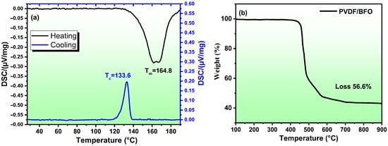
Figure 5.
DSC thermograms (a) and thermogravimetric curves of PVDF/BFO membrane (b).
The DSC endotherms (Figure 5a) show an asymmetric melting peak at Tm = 164.8 °C; this indicates the presence of several phases, confirming the XRD and FTIR results. Using Equation (2), the crystallinity can be calculated:
where is the sample enthalpy of fusion, calculated from heating DSC curve, is the heat of fusion of perfectly crystalline PVDF from the literature (104.7 J g−1), and φ is the weight fraction of the PVDF in the samples. The calculations showed that the crystallinity was about 92%. To evaluate the thermal stability and uniformity of the distribution of nanoparticles in the composite, a TGA analysis of the composite film was carried out. The measurements were carried out on five different sections of the synthesized film (four along the edges and one in the center). The averaged results are shown in Figure 5a. The discrepancies between the five measurements were no more than 10%, which indicates a fairly good uniformity of the distribution of nanoparticles in the sample. The figure shows that the weight loss was 56.6%. According to the synthesis procedure, the mass ratio of polymer/nanoparticles in percent should be 66.7/33.3%. The TGA result showed 56.6/43.6. This discrepancy can be explained by the fact that the TGA analysis was carried out in an argon atmosphere, as a result of which the polymer incompletely burned out and soot remained.
Regarding photocatalysis, it is very important to study the features of the interaction of a sample with light. The optical absorption spectra of pure BiFeO3 nanoparticles were presented in our previous studies [11,12]. Figure 6 shows the spectra of the optical absorption coefficient and the transport scattering coefficient . As can be seen, the coefficient of the polymer composite is a spectral contour formed by a wide, intense absorption band with a maximum in the wavelength range of 475.0 ± 25.0 nm, as well as a shoulder near the wavelengths of 650.0 ± 20.0 nm. Accounting for light scattering on the elements of the morphological structure made it possible to determine the adequate absorption value of the objects under study, which was = 10.0 ± 1.0 mm–1 for the extremum region. The spectral contour repeats the spectrum characteristic of pure nanoparticles.
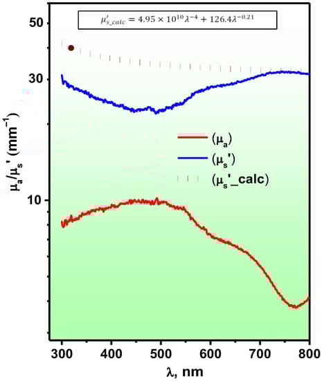
Figure 6.
Spectra of the optical absorption coefficient— and light scattering—, as well as the approximation of the scattering coefficient by a 2-power exponential function—.
In comparison with the shape of the scattering coefficient spectrum is a mirror image of the absorption spectrum. In the region of short wavelengths, a sagging of the contour is observed where (λ) takes on minimum values, while in the long-wavelength region of the spectrum, the scattering coefficient increases, acquiring the form of a smoother horizontal curve. The inverse symmetry of the absorption and scattering bands is apparently caused by the influence of strong absorption in which, due to an increase in the number of acts of interaction of light with polymer chromophores over the mean free path, the number of multiple scattering photons decreases. In general, the studied polymer film samples are characterized by a high level of light scattering in the range mm−1.
The analysis of the scattering coefficient via the turbidity spectrum method [56] encounters some difficulties due to significant distortions introduced by intense absorption in the 475.0 ± 25.0 nm wavelength region in the spectra. However, the use of a two-power exponential function of the type (where λ is the wavelength, and and are dimensionless parameters which are functions of the concentration of scattering particles, respectively, Rayleigh and Mie, and is the wave exponent characterizing the size of the Mie particles) makes it possible to predict with good accuracy the coefficient in the range of wavelengths greater than 700 nm using the function (see Figure 6), which looks like this:
According to the expression obtained and the slope of the spectral curve , Mie scattering provides the main contribution to the formation of the scattering coefficient in the long-wavelength spectral range. The obtained value of the wave exponent, indicates the presence of large scattering particles, which can be both structural elements of the polymer—spherulites and their aggregate complexes, with geometric dimensions ranging from 10 to 200 μm.
At the same time, the contribution of light scattering on particles of a small size manifests itself mainly in the short-wavelength region of the spectrum; however, the observed distortion, makes the estimate of their concentration very approximate—. The most potential Rayleigh scatterers, apparently, are bismuth ferrite nanoparticles and their agglomerates, the dimensions of which do not exceed hundreds of nanometers.
The result of microfluorescence studies of PVDF/BFO is shown in Figure 7. As can be seen from the figure, when excited at a wavelength of , the objects under study are characterized predominantly by bright green photoluminescence, although areas of red-wave luminescence can also be distinguishable (see Figure 7A). In particular, in the light of intrinsic fluorescence, elements of the morphological structure are clearly visible, with a spherical shape—granules, with a geometric cross-sectional diameter in the limit μm—and a pronounced glow of the shell. Moreover, the larger the spheroid, the higher the reradiation intensity of their surface. At the same time, the fragments of red fluorescence observed in the field of view apparently correspond to the zones of accumulation of structural elements of a much finer dispersion, which could be nanoparticles. These particles, aggregate interacting with polymer molecules, forming concentric structures up to 10 μm in size that are uniformly distributed over the field of the micrograph.
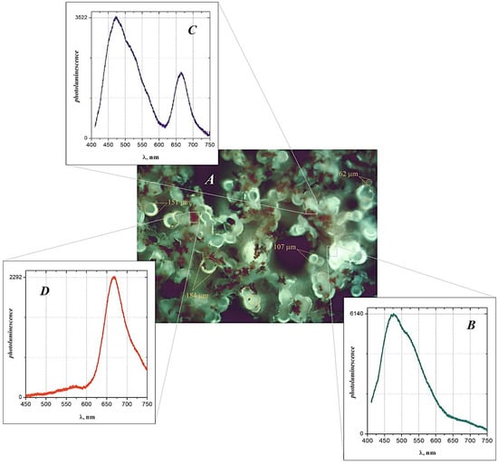
Figure 7.
Fluorescence micrograph (A) of polymer film at 500 magnification, as well as photoluminescence spectra of various regions of the polymer sample (B–D). Excitation wavelength of the glow, nm. The numbers show the diameter of the section of the structural elements of the sample.
The use of the confocal microscopy mode made it possible to reveal the spectral dependence of the laser-induced fluorescence of various fragments of the object under study. For example, for the pure polymer region (Figure 7B), as a rule, an intense glow is characteristic by a main maximum and a shoulder near the wavelengths and nm, respectively, as well as a gentle long-wavelength wing. For transition zones, which are a combination of a polymer and nanoparticles (Figure 7C), the sharp ignition of the spectral component at nm, with a decrease in the re-emission intensity at the wavelength of the main maximum of up to three times, is noteworthy. The observed changes in the fluorescence spectra progress, passing to areas of nanoparticle accumulation (Figure 7D), expressed as a further intensification of the red-wavelength luminescence band with the complete disappearance of the short-wavelength component.
Since the nature of the re-emission strongly depends on the accumulation of nanoparticles, it would be logical to assume that the red-wave emission band is associated with nanoparticles. However, the study of pure nanoparticles showed that, under this excitation mode, it lacks any luminescence bands (data not shown). Thus, the analysis and a comparison of the results of spectroscopic studies allow us to form a row of assumptions regarding the mechanism of fluorescence formation in the polymer composite. Perhaps this can be explained by the features of the polymer crystal structure, which strongly depend on the presence of nanoparticles in the region under study since it is known that nanoparticles in polymer matrices play the role of a nucleating agent and contribute both to the α → β → γ phase transitions and to an increase in the fraction of crystallinity. The mechanisms of induced fluorescence in “non-fluorescent” polymers with subfluorophore groups have been discussed in detail in a row of review papers in recent years [57,58,59]. One of the possible mechanisms for the formation of fluorescence in PVDF is the formation of self-assembled crystalline micellar aggregations, leading to an increase in the rigidity of the subfluorophores. One paper [60] indicated that PVDF also has a fluorescent effect due to the presence of a large number of F atoms with strong electron-withdrawing abilities. However, to confirm the exact mechanism, additional, more detailed studies are required which are beyond the scope of the present work.
Thus, the PVDF/BFO membranes have promise as a new type of photonic application for versatile, multifunctional stimulus-sensitive smart sensors.
The catalytic properties of the PVDF/BFO membrane were studied in the process of MB decomposition upon irradiation with visible and UV–visible light. The results are presented in Figure 8.
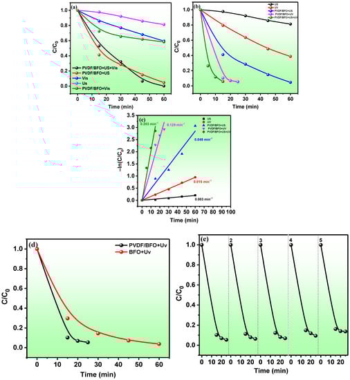
Figure 8.
PVDF/BFO MB catalytic degradation curves under visible light (a) and UV–visible light (b) irradiation; semi-logarithmic kinetic curves for experiments with UV–visible light (c); comparison of the catalytic activity of BFO nanoparticles and PVDF/BFO upon irradiation with UV–visible light (d); cycling experiments on the reuse of PVDF/BFO in photocatalysis by irradiation with UV–visible light (e).
Figure 8a shows the results of the PC decomposition of methylene blue under visible light irradiation. The results of the control experiments under the influence of only US (sonolysis) and light (photolysis) show that MB is quite stable. For 60 min of the experiment, degrees of decomposition of 19 and 41% were achieved during sonolysis and photolysis, respectively. A preliminary dark adsorption experiment under similar conditions demonstrated that MB is practically not adsorbed by the membrane. In the photocatalytic experiment, about 40% was also reached, indicating the absence of PC activity under this light source. According to our previous work, the BFO band gap is about 2.0 eV, which corresponds to 620 nm radiation. Probably, the absence of PC activity is due to the very low emission intensity of the spectral line of the MH lamp at this wavelength. In addition, it was observed from the optical measurements of the membrane that very strong light scattering appeared in the long-wavelength spectral range. The membrane showed high piezocatalytic activity (95% in 60 min). The rate constant for the piezocatalytic decomposition of MB was 16 times higher than for sonolysis (0.003 and 0.048 min–1). The high piezocatalytic activity of the membrane is due to the bi-piezocatalytic contribution from both the piezoactive PVDF polymer with a high level of crystallinity and a high proportion of the polar phase and from the ferroelectric BFO. BiFeO3 is a classic piezoelectric material with a large piezoelectric coefficient (d33) of the order of 100 pmV [61]. The high level of piezocatalytic activity of BFO nanoparticles was previously reported [62,63,64,65].
The mechanism of the piezocatalytic effect has not yet been precisely determined, and this issue is still a subject of discussion [66]. One of the generally accepted theories explains the effect by the fact that an ultrasonic wave acting on a liquid, propagating in the form of acoustic waves, is capable of generating cavitation microbubbles, during the collapse of which pressure from shock waves of up to 108 Pa is exerted on the piezocatalyst. The thermal effect from cavitation is capable of generating both electron–hole pairs in BFO nanoparticles and the surface piezoelectric potential in PVDF, all of which together leads to the generation of the highly oxidizing radicals ∙OH and ∙O2− [67]. Table S1 presents comparative results of the piezocatalytic activity during the ultrasonic treatment of composite membranes based on PVDF.
In experiments with a combination of piezocatalysis and simultaneous irradiation with visible light, the results confirmed the absence of PC activity in the membrane, and a degree of decomposition of 96% is the contribution of piezocatalysis only.
The results of MB decomposition under UV–visible irradiation are shown in Figure 8b. The degree of decomposition of 95% in the PC experiment was already reached by 20 min, indicating the high PC activity of the membrane. With piezophotocatalytic oxidation, MB had already reached 96% by 15 min. Figure 8c shows semi-logarithmic curves for the decomposition of MB under UV–visible light irradiation. The rate constants for sonolysis, photolysis, piezocatalysis, photocatalysis, and piezophotocatalysis were 0.003, 0.016, 0.048, 0.129, and 0.203 min–1, respectively. Under simultaneous exposure to light and ultrasound, the reaction rate increased 1.6 times relative to photocatalysis and 4.2 times relative to piezocatalysis. This effect is due to the fact that the piezopotential induced in both materials (PVDF and BFO) under the action of mechanical stress (pressure exerted by ultrasonic shock waves) leads to the spatial separation of the free charge carriers photogenerated in BFO (e− and h+), acting as a potential recombination limiter. In addition, the bending of the bands due to the piezoelectric potential facilitates and accelerates the migration of free charge carriers to the surface. When interacting with the reaction solution, these surface charge states lead to the generation of reactive oxygen species (ROS), which decompose the MB.
To understand whether the dielectric polymer affects the photocatalytic properties of the semiconductor filler, the photocatalytic activity of pure BFO was evaluated. Knowing the mass of the membrane and the mass fraction of nanoparticles in the membrane, the corresponding concentration of BFO was taken to maintain the similarity of the experimental conditions. The results are shown in Figure 8. As can be seen, the membrane exhibits a higher PC activity. In the absence of external mechanical action, this result is unexpected and illogical for several reasons:
- Firstly, the specific area of the photoactive surface and, accordingly, the number of active centers in the dispersed nanoparticles is much higher than in those immobilized in a polymer matrix;
- Secondly, from the SEM image of the section, it was seen that most of the nanoparticles are located in the bulk of the polymer and, taking into account the hydrophobicity of the membrane, the nanoparticles in the bulk should not come into contact with the solution;
- Thirdly, the presence of ultrawide-gap PVDF on the surface of the BFO should prevent the penetration of radiation to the BFO nanoparticles.
We observed a similar result in our previous work on PVDF/Fe2O3 [19], in which it was shown using XPS, UPS, and the frequency dependence of the permittivity that the presence of interfacial polarization at the PVDF/Fe2O3 interface leads to an increase in the density of the localized states in the bandgap of PVDF near the Fermi level, thereby leading to an increase in the photocatalytic activity of the composite.
The reusability of the samples was investigated for photocatalysis under UV–visible irradiation and is shown in Figure 8f. We observed a slight decrease in catalytic activity during five successive cycles of photocatalysis. This indicates the long-term stability of the membrane.
To experimentally confirm the generation of the piezopotential under mechanical action, a piezoelectric nanogenerator was assembled. The results are shown in Figure 9.
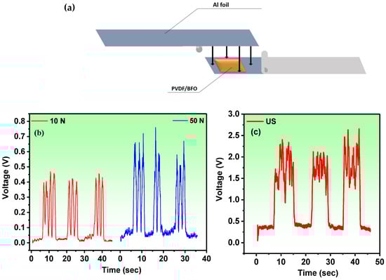
Figure 9.
(a) Schematic structure of the PVDF/BFO-based PENG. (b) The PVDF/BFO-based PENG time-dependent open-circuit voltages under finger press and (c) US stress.
Figure 9a demonstrates the schematic structure of the PVDF/BFO-based PENG. For comparison with the piezocatalytic experiment, the size of the membrane in the PENG corresponded to the size of the catalyst. The time-dependent open-circuit stresses under a finger press with various forces are presented in Figure 9b. The system produces open-circuit voltage values of about 450 mV that are adequately repeatable under a force of 10 N and around 650 mV under a force of 50 N. Additionally, with ultrasonic irradiation of the PVDF/BFO PENG, repeatable voltages (of around 2.5 V) were detected (Figure 9c). Furthermore, it was found that piezoelectric charges in the PVDF/BFO may be constantly stimulated by both mechanical pressure and ultrasonic waves. Such continuous stimulation results in an alternate internal electric field that can efficiently transfer charges to the PVDF/BFO–solution interface.
The magnetic hysteresis loops (M–Hs) of the initial BFO nanopowder and the PVDF/BFO composite are shown in Figure 10. Both samples show behavior typical of soft ferromagnetic materials, with saturation fields above 5 kOe. The saturation magnetization (Ms) for the original BFO was 0.436 and for the PVDF/BFO it was 0.0675 emu/g, which is almost an order of magnitude lower. The difference in the Ms values of these samples can be explained by the fact that the mass fraction of BFO in the composite was about 30%. A similar difference was also observed for the residual magnetization (Mr) (Table 1). The magnetic properties of the PVDF/BFO composite are correlated with the magnetic behavior of the BFO nanoparticles, which are dependent on the size of the crystallites and impurity phases and can be tuned by changing the synthesis and post-heat-treatment protocols [68,69]. Based on the results of the structural studies, we can conclude that bismuth ferrite provides the main contribution to the magnetic characteristics of the prepared PVDF/BFO composite.
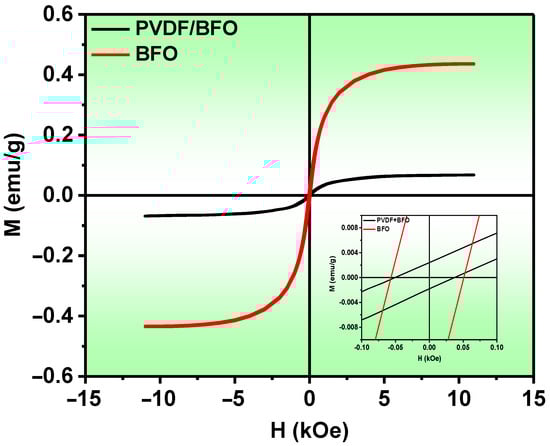
Figure 10.
M-H magnetization loops of BFO and PVDF/BFO.

Table 1.
Ms, Mr, and Hc for BFO and PVDF/BFO.
3. Materials and Methods
3.1. Synthesis of Samples
BFO nanopowders were synthesized via the combustion solution method [11]. Briefly, a stoichiometric mixture of iron and bismuth nitrates was mixed with glycine, and the mixture was heated with vigorous stirring at 300 °C until dehydration and flashing occurred. The resulting powder was annealed at 600 °C.
The composite films were fabricated through a simple solvent-casting technique. The process is shown schematically in Figure 11. A 10 wt.% solution of PVDF polymer was prepared in a mixture of DMSO/acetone solvents with a mass ratio of 70:30. The mixture was stirred on a Vortex shaker for 10 min and treated in an ultrasonic bath at 40 °C until a homogeneous solution was formed (Figure 11a). Then, an appropriate amount of BFO (5 wt%) was added to the solution and thoroughly mixed on a shaker and in an ultrasonic bath (50 °C) until the nanoparticles were uniformly distributed in the volume (Figure 11b,c). The suspension was transferred to a glass plate, and the excess was removed with a doctor blade (Figure 11d). The resulting film was then heated in a drying chamber at 85 °C for 12 h to remove the remaining solvent (Figure 11e).
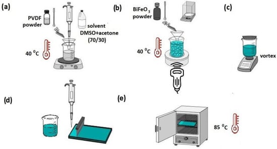
Figure 11.
Schematic representation of PVDF/BFO synthesis procedure.
3.2. Optical Properties
The studied samples were polymer films, 10.0 × 10.0 mm in size and d = 100.0 ± 10.0 µm thick, placed between quartz plates—a slide and a cover glass. In this case, the refractive index of the polymer films was taken equal to , and the refractive index of the quartz glasses was taken equal to . Measurements of the spectra of the total light transmission Tt and the diffuse reflection Rd for the objects under study were performed in the wavelength range of λ~300–1000 nm, using an Avasphere-50 integrating sphere (Avantes, Apeldoorn, The Netherlands). The illumination source was an AvaLight-DH-S-BAL combined a deuterium/halogen lamp (Avantes, Apeldoorn, The Netherlands) whose radiation was delivered to the sample via 600 μm fiber optic light guides. Photosignals were recorded using an MS3504i automated spectrometer (SOL-Instruments, Minsk, Belarus) combined with an HS-101(HR)-2048 × 122 CCD-matrix camera (Hamamatsu, Shizuoka, Japan) and a personal computer.
The study of the microfluorescent properties was carried out on a laser scanning confocal microscope MR-350 (SOL-Instruments, Minsk, Belarus), including an optical microscope Nikon-NiU (Nikon, Tokyo, Japan), with excitation of the glow by laser radiation at a wavelength of λex = 408 nm and registration with an MS3504i spectrometer.
The final data of the spectrophotometric coefficients Tt and Rd were defined as:
where and are the transmission and reflection spectra of the samples; and are the reference signal spectra, measured with quartz plates; is the integrating sphere signal with covered input and open output ports; is the signal for a sphere with open optical ports. The calculation of the spectral dependence of the coefficients of optical absorption and light scattering was carried out using the inverse method of the Monte Carlo numerical simulation, developed and described in detail in the works [70,71].
- Characterization
The TG/DSC curves were recorded on an STA 449 F3 Jupiter (Netzsch, Selb, Germany) simultaneous thermal analysis instrument at a heating rate of 10 °C/min (7 °C/min) in an argon atmosphere in alundum crucibles. Data processing and peak integration were carried out using built-in application programs from Netzsch.
The crystalline phases of the samples were identified from diffraction patterns taken on an Empyrean PANalytical X-ray diffractometer (PANalytical, Malvern, UK) with CuK α radiation (λ = 1.5418 Å).
The morphology of the synthesized samples was investigated through the use of scanning electron microscopy (ASPEX Express, Delmont, PA, USA) and transmission electron microscopy (TEM) Helios NanoLab 660 FEI (Thermo Fisher Scientific, Waltham, MA, USA).
The SEM image of the composite sample was obtained using an Aspex scanning electron microscope at various accelerating voltages.
The magnetic properties of the composite were studied using a LakeShore 7400 vibrating magnetometer (Lake Shore Cryotronics, Inc., Westerville, OH, USA) at room temperature.
- b.
- PENG Measurements
To investigate the ability to collect mechanical energy, a piezoelectric current generator (PENG) was assembled. A PVDF/BFO film with the dimensions 2 × 1.5 cm2, which was used as an active piezoelectric component for the piezoelectric nanogenerator (PENG), was placed between the upper and lower Al foil electrodes. For compactness, the entire multi-layer structure was then thoroughly laminated with polypropylene (PP) adhesive tape. From both sides of the electrodes, conductive Al tapes were attached. The piezopotential was measured in two ways:
- The PENG was fixed on a flat surface and pressed with different pressure forces (10 and 50 N);
- The PENG was immersed in an ultrasonic bath, fixed stationary, and the ultrasound was turned on and off.
Measurements of the output voltage signal of the manufactured PENG were taken using an Arduino UNO R3 programmable board in the Arduino 1.8.19 application, and a 2 MΩ resistor was also used in the circuit to eliminate unwanted noise (Figure S1).
- c.
- Catalytic activity
A solution of methylene blue (MB) was used as decomposable organic matter. A sample of a polymer film (PVDF/BiFeO3), measuring 2 cm × 1.5 cm in size and weighing 33.7 mg, was immersed in a beaker with an MB solution (V—20 mL; C0—1 mg/L). It should be noted that due to hydrophobicity, the membrane was always on the surface of the solution. An ultrasonic (US) bath with a power of 120 W and a frequency of 40 kHz (FanYing Sonic, Shenzhen, China) was used as the source of mechanical action (to excite the piezoelectric effect). The location of the glass in the ultrasonic bath plays a very important role in the experiment. The exact parameters of the experiment in the ultrasonic bath are shown in Figure S1. A high-pressure mercury lamp without a phosphor layer (Philips, 250 W) was used as a UV/visible light source. A metal halogen (MH) lamp (Osram, 70 W) was used as a visible light source. The distance from the light source to the reactor was 10 cm. The reactor was maintained at a constant temperature of 26 °C. The experiment lasted 60 min, and samples were taken every 15 min. The sample was analyzed on an SF-2000 spectrophotometer at a wavelength of 663.7 nm. To distinguish between the actions of various factors, the following experiments were carried out on the decomposition of MB:
- Exposure to light with a catalyst (photocatalysis). This eliminated the mixing of the solution.
- Exposure to light without a catalyst (photolysis).
- Exposure to ultrasound without a catalyst (sonolysis).
- Exposure to ultrasound with a catalyst (piezocatalysis).
- Exposure to light and ultrasound with a catalyst (piezophotocatalysis).
The degree of dye decomposition was determined from the ratio of the current dye concentration to the initial one.
4. Conclusions
This paper presents the results of synthesizing a multi-stimuli-sensitive porous composite membrane based on polyvinylidene fluoride and bismuth ferrite via the doctor blade casting method and the thermally induced phase separation (TIPS) technique. The addition of 5 wt.% of nanoparticles in the polymer matrix led to the formation of high crystallinity (92%) and a high proportion of the polar phase (94%). The sample exhibited laser-induced fluorescence with maxima at 475 and 665 nm, which depended on the presence of nanoparticles in the polymer matrix. The magnetic properties were characterized by weak ferromagnetism with a saturation magnetization of about 0.0675 emu/g. The ability to collect mechanical energy was demonstrated in an experiment with a PENG, which showed that at a maximum load of 50 N, a piezopotential of 0.65 V and an ultrasonic effect of 2.5 V were generated.
High photo-, piezo-, and piezo-photocatalytic activities were demonstrated during the decomposition of methylene blue dye under irradiation with visible and UV–visible light. The rate of the piezocatalytic decomposition of MB was 16 times higher than for sonolysis. When irradiated with UV–visible light, the degree of photocatalytic decomposition of MB was 95% in 20 min. Under simultaneous exposure to light and ultrasound, the reaction rate increased 1.6 times relative to photocatalysis and 4.2 times relative to piezocatalysis.
Supplementary Materials
The following supporting information can be downloaded at: https://www.mdpi.com/article/10.3390/catal13050874/s1, Figure S1: Emission spectra (a)—70 W metal halide lamp used as a source of visible light, (b)—250 W discharge mercury vapor lamp with a preliminary removed phosphor layer; Figure S2: Scheme of the location of the glass in the ultrasonic bath. (A) Top view (B) Side view; Figure S3: Scheme of signal measurements of the manufactured PENG; Table S1: Comparison table for piezocatalysis. [24,27,32,72,73,74,75,76,77].
Author Contributions
Conceptualization, F.O., N.A. and V.R.; Methodology, S.R. and A.A. (Abdulkarim Amirov); Software, A.S.; Validation, D.S. (Dinara Sobola), S.R. and F.O.; Formal Analysis, R.M., S.R. and V.R.; Investigation, A.A. (Abdulkarim Amirov), A.A. (Akhmed Amirov), K.R., K.G., D.S. (Daud Selimov), D.S. (Dinara Sobola), S.G., M.A., R.G., A.S., A.R. and A.M.; Resources, F.O. and V.R.; Data curation, F.O., N.A. and K.G.; Writing—Original Draft Preparation, F.O., K.G. and N.A.; Writing—Review and Editing, F.O., K.G. and N.A.; Visualization, A.A. (Abdulkarim Amirov), K.G. and F.O.; Supervision, F.O. and A.A. (Abdulkarim Amirov); Project Administration, F.O. and V.R.; Funding Acquisition, F.O. and V.R. All authors have read and agreed to the published version of the manuscript.
Funding
The study was funded by the Russian Science Foundation under Project No. 21-72-30032, with respect to the protocol development and composite membrane synthesis, basic SEM/XRD/TGA/DSC characterization, magnetic measurements, and finger-pressure piezo-response studies, and Project No. 22-73-10091 with respect to the synthesis of BFO nanoparticles and their TEM/XRD studies, the study of the photo-, piezo- and piezo-photocatalytic properties of composite membranes and the study of their optical characteristics and piezo-response under ultrasonic exposure.
Data Availability Statement
The data that support the findings of this study are available from the corresponding authors upon reasonable request.
Acknowledgments
We acknowledge CzechNanoLab Research Infrastructure supported by MEYS CR (LM2023051) and FEKT-S-23-8228.
Conflicts of Interest
The authors declare no conflict of interest.
References
- Nazri, M.K.H.M.; Sapawe, N. A short review on photocatalytic toward dye degradation. Mater. Today Proc. 2020, 31, A42–A47. [Google Scholar] [CrossRef]
- Oturan, M.A.; Aaron, J.J. Advanced Oxidation Processes in Water/Wastewater Treatment: Principles and Applications. A Review. Crit. Rev. Environ. Sci. Technol. 2014, 44, 2577–2641. [Google Scholar] [CrossRef]
- Ajmal, A.; Majeed, I.; Malik, R.N.; Idriss, H.; Nadeem, M.A. Principles and mechanisms of photocatalytic dye degradation on TiO2 based photocatalysts: A comparative overview. RSC Adv. 2014, 4, 37003–37026. [Google Scholar] [CrossRef]
- Miklos, D.B.; Remy, C.; Jekel, M.; Linden, K.G.; Drewes, J.E.; Hübner, U. Evaluation of advanced oxidation processes for water and wastewater treatment–A critical review. Water Res. 2018, 139, 118–131. [Google Scholar] [CrossRef] [PubMed]
- Muslimov, A.; Orudzhev, F.; Gadzhiev, M.; Selimov, D.; Tyuftyaev, A.; Kanevsky, V. Facile Synthesis of Ti/TiN/TiON/TiO2 Composite Particles for Plasmon-Enhanced Solar Photocatalytic Decomposition of Methylene Blue. Coatings 2022, 12, 1741. [Google Scholar] [CrossRef]
- Isaev, A.B.; Shabanov, N.S.; Orudzhev, F.F. Influence of oxygen pressure to photoelectrochemical oxidation C.I. direct black 22 on TiO2 nanotube array photoanode. Int. J. Environ. Sci. Technol. 2018, 15, 1609–1618. [Google Scholar] [CrossRef]
- Isaev, A.B.; Shabanov, N.S.; Orudzhev, F.F.; Giraev, K.M.; Emirov, R.M. Electrochemical synthesis and photocatalytic properties of α-Fe2O3. J. Nanosci. Nanotechnol. 2017, 17, 4498–4503. [Google Scholar] [CrossRef]
- Li, L.; Gao, H.; Yi, Z.; Wang, S.; Wu, X.; Li, R.; Yang, H. Comparative investigation on synthesis, morphological tailoring and photocatalytic activities of Bi2O2CO3 nanostructures. Colloids Surf. A Physicochem. Eng. Asp. 2022, 644, 128758. [Google Scholar] [CrossRef]
- Wang, Y.; Sun, X.; Yi, Z.; Wu, X.; Liu, G.; Pu, Z.; Yang, H. Construction of a Z-scheme Ag2MoO4/BiOBr heterojunction for photocatalytically removing organic pollutants. Dalton Trans. 2022, 51, 18652–18666. [Google Scholar] [CrossRef]
- Haruna, A.; Abdulkadir, I.; Idris, S.O. Photocatalytic activity and doping effects of BiFeO3 nanoparticles in model organic dyes. Heliyon 2020, 6, e03237. [Google Scholar] [CrossRef] [PubMed]
- Alikhanov, N.M.R.; Rabadanov, M.K.; Orudzhev, F.F.; Gadzhimagomedov, S.K.; Emirov, R.M.; Sadykov, S.A.; Kallaev, S.N.; Ramazanov, S.M.; Abdulvakhidov, K.G.; Sobola, D. Size-dependent structural parameters, optical, and magnetic properties of facile synthesized pure-phase BiFeO3. J. Mater. Sci. Mater. Electron. 2021, 32, 13323–13335. [Google Scholar] [CrossRef]
- Orudzhev, F.F.; Alikhanov, N.-R.; Rabadanov, M.K.; Ramazanov, S.M.; Isaev, A.B.; Gadzhimagomedov, S.K.; Aliyev, A.S.; Abdullaev, V.R. Synthesis and study of the properties of magnetically separable nanophotocatalyst BiFeO3. Chem. Probl. 2018, 16, 484–495. [Google Scholar] [CrossRef]
- Orudzhev, F.F.; Alikhanov, N.M.R.; Ramazanov, S.M.; Sobola, D.S.; Murtazali, R.K.; Ismailov, E.H.; Gasimov, R.D.; Aliev, A.S.; Ţălu, Ş. Morphotropic Phase Boundary Enhanced Photocatalysis in Sm Doped BiFeO3. Molecules 2022, 27, 7029. [Google Scholar] [CrossRef] [PubMed]
- Hengky, C.; Moya, X.; Mathur, N.D.; Dunn, S. Evidence of high rate visible light photochemical decolourisation of Rhodamine B with BiFeO3 nanoparticles associated with BiFeO3 photocorrosion. RSC Adv. 2012, 2, 11843–11849. [Google Scholar] [CrossRef]
- Li, X.; Wang, W.; Dong, F.; Zhang, Z.; Han, L.; Luo, X.; Huang, J.; Feng, Z.; Chen, Z.; Jia, G.; et al. Recent Advances in Noncontact External-Field-Assisted Photocatalysis: From Fundamentals to Applications. ACS Catal. 2021, 11, 4739–4769. [Google Scholar] [CrossRef]
- Lv, T.; Li, J.; Arif, N.; Qi, L.; Lu, J.; Ye, Z.; Zeng, Y.J. Polarization and external-field enhanced photocatalysis. Matter 2022, 5, 2685–2721. [Google Scholar] [CrossRef]
- Hu, C.; Tu, S.; Tian, N.; Ma, T.; Zhang, Y.; Huang, H. Photocatalysis Enhanced by External Fields. Angew. Chem. 2021, 133, 16445–16464. [Google Scholar] [CrossRef]
- Mi, Y.; Fang, W.; Jiang, Y.; Yang, Y.; Liu, Y.; Shangguan, W. Recent Advancements in Photocatalysis Coupling by External Physical Fields. Catalysts 2022, 12, 1042. [Google Scholar] [CrossRef]
- Orudzhev, F.; Ramazanov, S.; Sobola, D.; Kaspar, P.; Trčka, T.; Částková, K.; Kastyl, J.; Zvereva, I.; Wang, C.; Selimov, D.; et al. Ultrasound and water flow driven piezophototronic effect in self-polarized flexible α-Fe2O3 containing PVDF nanofibers film for enhanced catalytic oxidation. Nano Energy 2021, 90, 106586. [Google Scholar] [CrossRef]
- Dallaev, R.; Pisarenko, T.; Sobola, D.; Orudzhev, F.; Ramazanov, S.; Trčka, T. Brief Review of PVDF Properties and Applications Potential. Polymers 2022, 14, 4793. [Google Scholar] [CrossRef] [PubMed]
- Sobola, D.; Kaspar, P.; Částková, K.; Dallaev, R.; Papež, N.; Sedlák, P.; Trčka, T.; Orudzhev, F.; Kaštyl, J.; Weiser, A.; et al. PVDF Fibers Modification by Nitrate Salts Doping. Polymers 2021, 13, 2439. [Google Scholar] [CrossRef]
- Dai, B.; Huang, H.; Wang, W.; Chen, Y.; Lu, C.; Kou, J.; Wang, L.; Wang, F.; Xu, Z. Greatly enhanced photocatalytic activity by organic flexible piezoelectric PVDF induced spatial electric field. Catal. Sci. Technol. 2017, 7, 5594–5601. [Google Scholar] [CrossRef]
- Yin, X.; Wu, W.; Zhang, F.; Li, L.; Kou, J.; Lu, C. Synergetic effect of piezoelectricity and heterojunction on photocatalytic performance. J. Photochem. Photobiol. A Chem. 2020, 400, 112661. [Google Scholar] [CrossRef]
- Ma, W.; Yao, B.; Zhang, W.; He, Y.; Yu, Y.; Niu, J. Fabrication of PVDF-based piezocatalytic active membrane with enhanced oxytetracycline degradation efficiency through embedding few-layer E-MoS2 nanosheets. Chem. Eng. J. 2021, 415, 129000. [Google Scholar] [CrossRef]
- Cui, Y.; Yang, L.; Zheng, J.; Wang, Z.; Li, B.; Yan, Y.; Meng, M. Synergistic interaction of Z-scheme 2D/3D g-C3N4/BiOI heterojunction and porous PVDF membrane for greatly improving the photodegradation efficiency of tetracycline. J. Colloid Interface Sci. 2021, 586, 335–348. [Google Scholar] [CrossRef] [PubMed]
- Yang, C.; Wang, P.; Li, J.; Wang, Q.; Xu, P.; You, S.; Zheng, Q.; Zhang, G. Photocatalytic PVDF ultrafiltration membrane blended with visible-light responsive Fe(III)-TiO2 catalyst: Degradation kinetics, catalytic performance and reusability. Chem. Eng. J. 2021, 417, 129340. [Google Scholar] [CrossRef]
- Bagchi, B.; Hoque, N.A.; Janowicz, N.; Das, S.; Tiwari, M.K. Re-usable self-poled piezoelectric/piezocatalytic films with exceptional energy harvesting and water remediation capability. Nano Energy 2020, 78, 105339. [Google Scholar] [CrossRef]
- Tong, W.; Zhang, Y.; Huang, H.; Xiao, K.; Yu, S.; Zhou, Y.; Liu, L.; Li, H.; Liu, L.; Huang, T.; et al. A highly sensitive hybridized soft piezophotocatalyst driven by gentle mechanical disturbances in water. Nano Energy 2018, 53, 513–523. [Google Scholar] [CrossRef]
- Álvarez, P.M.; Jaramillo, J.; López-Piñero, F.; Plucinski, P.K. Preparation and characterization of magnetic TiO2 nanoparticles and their utilization for the degradation of emerging pollutants in water. Appl. Catal. B Environ. 2010, 100, 338–345. [Google Scholar] [CrossRef]
- Sun, X.X.; Liu, G.; Li, R.; Meng, Y.; Wu, J. Polyporous PVDF/TiO2 photocatalytic composites for photocatalyst fixation, recycle, and repair. J. Am. Ceram. Soc. 2021, 104, 6290–6298. [Google Scholar] [CrossRef]
- Lin, H.M.; Chang, K.S. Synergistic piezophotocatalytic and photoelectrochemical performance of poly(vinylidene fluoride)–ZnSnO3 and poly(methyl methacrylate)–ZnSnO3 nanocomposites. RSC Adv. 2017, 7, 30513–30520. [Google Scholar] [CrossRef]
- Rabadanova, A.; Rabadanova, A.; Abdurakhmanov, M.; Gulakhmedov, R.; Shuaibov, A.; Selimov, D.; Sobola, D.; Částková, K.; Ramazanov, S.; Orudzhev, F. Piezo-, photo- and piezophotocatalytic activity of electrospun fibrous PVDF/CTAB membrane. Chim. Techno Acta 2022, 9, 20229420. [Google Scholar] [CrossRef]
- Sasmal, A.; Sen, S.; Devi, P.S. Role of suppressed oxygen vacancies in the BiFeO3 nanofiller to improve the polar phase and multifunctional performance of poly(vinylidene fluoride). Phys. Chem. Chem. Phys. 2019, 21, 5974–5988. [Google Scholar] [CrossRef] [PubMed]
- Sasmal, A.; Patra, A.; Devi, P.S.; Sen, S. Hydroxylated BiFeO3 as efficient fillers in poly(vinylidene fluoride) for flexible dielectric, ferroelectric, energy storage and mechanical energy harvesting application. Dalt. Trans. 2021, 50, 1824–1837. [Google Scholar] [CrossRef] [PubMed]
- Bhadra, D.; Masud, M.G.; Sarkar, S.; Sannigrahi, J.; De, S.K.; Chaudhuri, B.K. Synthesis of PVDF/BiFeO3 nanocomposite and observation of enhanced electrical conductivity and low-loss dielectric permittivity at percolation threshold. J. Polym. Sci. Part B Polym. Phys. 2012, 50, 572–579. [Google Scholar] [CrossRef]
- Kum-onsa, P.; Chanlek, N.; Putasaeng, B.; Thongbai, P. Improvement in dielectric properties of poly(vinylidene fluoride) by incorporation of Au–BiFeO3 hybrid nanoparticles. Ceram. Int. 2020, 46, 17272–17279. [Google Scholar] [CrossRef]
- Moharana, S.; Mahaling, R.N. Preparation and properties of Benzoxazine (BA) based BiFeO3-Poly(vinylidene fluoride) (PVDF) Composites: Enhanced Dielectric Constant and Suppressed Loss. Polym. Technol. Mater. 2021, 60, 1122–1134. [Google Scholar] [CrossRef]
- Rana, D.K.; Kundu, S.K.; Choudhary, R.J.; Basu, S. Enhancement of electrical and magnetodielectric properties of BiFeO3 incorporated PVDF flexible nanocomposite films. Mater. Res. Express 2019, 6, 0850d9. [Google Scholar] [CrossRef]
- Saleh Medina, L.M.; Negri, R.M. Dielectric Behavior and Electro-Magnetic Coupling at Room Temperature in BiFeO3/PVDF and CoFe2O4/PVDF Composites. J. Phys. Chem. C 2017, 121, 27683–27692. [Google Scholar] [CrossRef]
- Hou, J.; Wang, H. Synthesis and Characterization of Organic–Inorganic Complex. J. Nanoelectron. Optoelectron. 2021, 16, 466–470. [Google Scholar] [CrossRef]
- Sasmal, A.; Sen, S.; Devi, P.S. Frequency dependent energy storage and dielectric performance of Ba–Zr Co-doped BiFeO3 loaded PVDF based mechanical energy harvesters: Effect of corona poling. Soft Matter 2020, 16, 8492–8505. [Google Scholar] [CrossRef]
- Li, Y.; Wang, Z.; Li, Y.; Yi, Z. Enhanced breakdown strength of PVDF textile composites by BiFeO3 fibers in low loading. J. Mater. Sci. Mater. Electron. 2022, 33, 3215–3224. [Google Scholar] [CrossRef]
- Sosa, M.D.; Levy, I.K.; Owusu, F.; Nüesch, F.; Opris, D.; Negri, R.M.; Saleh Medina, L.M. Stress effects on the impedance and ferroelectricity of PVDF- BiFeO3-MWCNT films using xanthan gum as dispersant. Mater. Chem. Phys. 2022, 286, 126175. [Google Scholar] [CrossRef]
- Ilić, N.; Teixeira, G.F.; Bobić, J.; Spasojević, V.; Džunuzović, A.; Petrović, M.V.; Zaghete, M.A.; Stojanović, B. Auto-combustion synthesis as a method for preparing BiFeO3 powders and flexible BiFeO3/PVDF films with improved magnetic properties. Influence of doping ion position, size and valence on electric properties. Mater. Sci. Eng. B 2022, 280, 115686. [Google Scholar] [CrossRef]
- Dash, S.; Choudhary, R.N.P.; Goswami, M.N. Enhanced dielectric and ferroelectric properties of PVDF-BiFeO3 composites in 0–3 connectivity. J. Alloys Compd. 2017, 715, 29–36. [Google Scholar] [CrossRef]
- Reddy, A.V.; Sekhar, K.C.; Dabra, N.; Nautiyal, A.; Hundal, J.S.; Pathak, N.P.; Nath, R. Ferroelectric and Magnetic Properties of Hot-Pressed BiFeO3-PVDF Composite Films. Int. Sch. Res. Netw. ISRN Mater. Sci. 2011, 2011, 142968. [Google Scholar] [CrossRef]
- Kumar, A.; Patel, P.K.; Yadav, K.L.; Singh, Y.; Kumar, N.; Abdullah; Sharma, G.; Singh, S. Enhanced magnetoelectric coupling response in hot pressed BiFeO3 and polymer composite films: Effect of magnetic field on grain boundary and grain resistance. Mater. Res. Bull. 2022, 145, 111527. [Google Scholar] [CrossRef]
- Tuluk, A.; Mahon, T.; van der Zwaag, S.; Groen, P. Estimating the true piezoelectric properties of BiFeO3 from measurements on BiFeO3-PVDF terpolymer composites. J. Alloys Compd. 2021, 868, 159186. [Google Scholar] [CrossRef]
- Orudzhev, F.; Sobola, D.; Ramazanov, S.; Částková, K.; Papež, N.; Selimov, D.A.; Abdurakhmanov, M.; Shuaibov, A.; Rabadanova, A.; Gulakhmedov, R.; et al. Piezo-Enhanced Photocatalytic Activity of the Electrospun Fibrous Magnetic PVDF/BiFeO3 Membrane. Polymers 2023, 15, 246. [Google Scholar] [CrossRef]
- Martins, P.; Lopes, A.C.; Lanceros-Mendez, S. Electroactive phases of poly(vinylidene fluoride): Determination, processing and applications. Prog. Polym. Sci. 2014, 39, 683–706. [Google Scholar] [CrossRef]
- Kaur, G.A.; Kumar, S.; Shandilya, M. Fabrication of piezoelectric nanogenerator based on P(VDF-HFP) electrospun nanofiber mat-impregnated lead-free BCZT nanofillers. J. Mater. Sci. Mater. Electron. 2020, 31, 20303–20314. [Google Scholar] [CrossRef]
- Cai, X.; Lei, T.; Sun, D.; Lin, L. A critical analysis of the α, β and γ phases in poly(vinylidene fluoride) using FTIR. RSC Adv. 2017, 7, 15382–15389. [Google Scholar] [CrossRef]
- Sasmal, A.; Patra, A.; Maity, S.; Pratihar, S.; Sen, S. Multiferroic BiFeO3-based hydrophobic polymer composites for polarization rationalization-induced piezo-tribo hybrid energy harvesting and versatile self-powered mechanosensing. Sustain. Energy Fuels 2022, 6, 4652–4668. [Google Scholar] [CrossRef]
- Gregorio, R.; Cestari, M. Effect of crystallization temperature on the crystalline phase content and morphology of poly(vinylidene fluoride). J. Polym. Sci. Part B Polym. Phys. 1994, 32, 859–870. [Google Scholar] [CrossRef]
- Gregorio, R. Determination of the α, β, and γ crystalline phases of poly(vinylidene fluoride) films prepared at different conditions. J. Appl. Polym. Sci. 2006, 100, 3272–3279. [Google Scholar] [CrossRef]
- Welch, A.J.; Van Gemert, M.J.C. Optical-Thermal Response of Laser-Irradiated Tissue; Springer: Amsterdam, The Netherlands, 2011; ISBN 9789048188307. [Google Scholar]
- Chatterjee, D.P.; Pakhira, M.; Nandi, A.K. Fluorescence in “nonfluorescent” Polymers. ACS Omega 2020, 5, 30747–30766. [Google Scholar] [CrossRef]
- Zhu, S.; Song, Y.; Shao, J.; Zhao, X.; Yang, B. Non-Conjugated Polymer Dots with Crosslink-Enhanced Emission in the Absence of Fluorophore Units. Angew. Chemie Int. Ed. 2015, 54, 14626–14637. [Google Scholar] [CrossRef] [PubMed]
- Feng, T.; Zhu, S.; Zeng, Q.; Lu, S.; Tao, S.; Liu, J.; Yang, B. Supramolecular Cross-Link-Regulated Emission and Related Applications in Polymer Carbon Dots. ACS Appl. Mater. Interfaces 2018, 10, 12262–12277. [Google Scholar] [CrossRef] [PubMed]
- Pakhira, M.; Ghosh, R.; Rath, S.P.; Chatterjee, D.P.; Nandi, A.K. Zwitterionic Poly(vinylidene fluoride) Graft Copolymer with Unexpected Fluorescence Property. Langmuir 2019, 35, 5525–5533. [Google Scholar] [CrossRef] [PubMed]
- You, H.; Wu, Z.; Zhang, L.; Ying, Y.; Liu, Y.; Fei, L.; Chen, X.; Jia, Y.; Wang, Y.; Wang, F.; et al. Harvesting the Vibration Energy of BiFeO3 Nanosheets for Hydrogen Evolution. Angew. Chem. 2019, 131, 11905–11910. [Google Scholar] [CrossRef]
- Mushtaq, F.; Chen, X.; Hoop, M.; Torlakcik, H.; Pellicer, E.; Sort, J.; Gattinoni, C.; Nelson, B.J.; Pané, S. Piezoelectrically Enhanced Photocatalysis with BiFeO3 Nanostructures for Efficient Water Remediation. iScience 2018, 4, 236–246. [Google Scholar] [CrossRef] [PubMed]
- Liu, Y.L.; Wu, J.M. Synergistically catalytic activities of BiFeO3/TiO2 core-shell nanocomposites for degradation of organic dye molecule through piezophototronic effect. Nano Energy 2019, 56, 74–81. [Google Scholar] [CrossRef]
- Long, J.; Ren, T.; Han, J.; Li, N.; Chen, D.; Xu, Q.; Li, H.; Lu, J. Heterostructured BiFeO3@CdS nanofibers with enhanced piezoelectric response for efficient piezocatalytic degradation of organic pollutants. Sep. Purif. Technol. 2022, 290, 120861. [Google Scholar] [CrossRef]
- Zhang, Q.; Jia, Y.; Chen, J.; Wang, X.; Zhang, L.; Chen, Z.; Wu, Z. Strongly enhanced piezocatalysis of BiFeO3/ZnO heterostructure nanomaterials. New J. Chem. 2023, 47, 3471–3480. [Google Scholar] [CrossRef]
- Bößl, F.; Comyn, T.P.; Cowin, P.I.; García-García, F.R.; Tudela, I. Piezocatalytic degradation of pollutants in water: Importance of catalyst size, poling and excitation mode. Chem. Eng. J. Adv. 2021, 7, 100133. [Google Scholar] [CrossRef]
- Chen, X.; Dai, J.; Shi, G.; Li, L.; Wang, G.; Yang, H. Sonocatalytic degradation of Rhodamine B catalyzed by β-Bi2O3 particles under ultrasonic irradiation. Ultrason. Sonochem. 2016, 29, 172–177. [Google Scholar] [CrossRef]
- Park, T.J.; Papaefthymiou, G.C.; Viescas, A.J.; Moodenbaugh, A.R.; Wong, S.S. Size-dependent magnetic properties of single-crystalline multiferroic BiFeO3 nanoparticles. Nano Lett. 2007, 7, 766–772. [Google Scholar] [CrossRef] [PubMed]
- Sheoran, N.; Saini, M.; Kumar, A.; Kumar, V.; Kumar, T.; Sheoran, M. Size dependent morphology, magnetic and dielectric properties of BiFeO3 nanoparticles. MRS Adv. 2019, 4, 1659–1665. [Google Scholar] [CrossRef]
- Wang, L.; Steven L Jacques, P.D. Monte Carlo Modeling of Light Transport in Multi-Layered Tissues in Standard C; University of Texas M. D. Anderson Cancer Center: Houston, TX, USA, 1992. [Google Scholar]
- Giraev, K.M.; Ashurbekov, N.A.; Magomedov, M.A.; Murtazaeva, A.A.; Medzhidov, R.T. The effect of pathological processes on absorption and scattering spectra of samples of bile and pancreatic juice. Opt. Spectrosc. (Engl. Transl. Opt. Spektrosk.) 2015, 119, 162–170. [Google Scholar] [CrossRef]
- Verma, S.; Sharma, M.; Vaish, R. Photo-piezocatalysis in electrospun PVDF + WS2 membrane. Environ. Sci. Nano 2022, 9, 3885–3899. [Google Scholar] [CrossRef]
- Singh, G.; Sharma, M.; Vaish, R. Flexible Ag@LiNbO3/PVDF Composite Film for Piezocatalytic Dye/Pharmaceutical Degradation and Bacterial Disinfection. ACS Appl. Mater. Interfaces 2021, 13, 22914–22925. [Google Scholar] [CrossRef] [PubMed]
- Jiang, B.; Xue, X.; Mu, Z.; Zhang, H.; Li, F.; Liu, K.; Wang, W.; Zhang, Y.; Li, W.; Yang, C.; et al. Contact-Piezoelectric Bi-Catalysis of an Electrospun ZnO@PVDF Composite Membrane for Dye Decomposition. Molculars 2022, 27, 8579. [Google Scholar] [CrossRef] [PubMed]
- Shi, J.; Zeng, W.; Dai, Z.; Wang, L.; Wang, Q.; Lin, S.; Xiong, Y.; Yang, S.; Shang, S.; Chen, W.; et al. Piezocatalytic Foam for Highly Efficient Degradation of Aqueous Organics. Small Sci. 2021, 1, 2000011. [Google Scholar] [CrossRef]
- Raju, T.D.; Veeralingam, S.; Badhulika, S. Polyvinylidene Fluoride/ZnSnO3 Nanocube/Co3O4 Nanoparticle Thermoplastic Composites for Ultrasound-Assisted Piezo-Catalytic Dye Degradation. ACS Appl. Nano Mater. 2020, 3, 4777–4787. [Google Scholar] [CrossRef]
- Li, F.; Shan, B.; Zhao, X.; Ji, C.; Li, Z.; Yu, J.; Xu, S.; Jiao, Y.; Zhang, C.; Man, B. Plasmonic enhanced piezoelectric photoresponse with flexible PVDF@ Ag-ZnO/Au composite nanofiber membranes. Optics Express 2022, 30, 32509–32527. [Google Scholar] [CrossRef] [PubMed]
Disclaimer/Publisher’s Note: The statements, opinions and data contained in all publications are solely those of the individual author(s) and contributor(s) and not of MDPI and/or the editor(s). MDPI and/or the editor(s) disclaim responsibility for any injury to people or property resulting from any ideas, methods, instructions or products referred to in the content. |
© 2023 by the authors. Licensee MDPI, Basel, Switzerland. This article is an open access article distributed under the terms and conditions of the Creative Commons Attribution (CC BY) license (https://creativecommons.org/licenses/by/4.0/).