Abstract
Cyber-physical systems have emerged as a new engineering paradigm, which combine the cyber and physical world with comprehensive computational and analytical tools to solve complex tasks. In cyber-physical systems, components are developed to detect failures, prevent failures, or mitigate the failures of a system. Sensors gather real-time data as an input to the system for further processing. Therefore, the whole cyber-physical system depends on sensors to accomplish their tasks and the failure of one sensor may lead to the failure of the whole system. To address this issue, we present an approach that utilizes the Failure Modes, Effects, and Criticality Analysis, which is a prominent hazard analysis technique to increase the understanding of risk and failure prevention. In our approach, we transform the Failure Modes, Effects, and Criticality Analysis model into a UML(Unified Modeling Language) class diagram, and then a knowledge base is constructed based on the derived UML class diagram. Finally, the UML class diagram is used to build an ontology. The proposed approach employs a 5C architecture for smart industries for its systematic application. Lastly, we use a smart home case study to validate our approach.
1. Introduction
In the era of the fourth industrial revolution, a new paradigm of an engineering approach has emerged, the Cyber-Physical System (CPS), which handles complex tasks in various fields of information technology, such as in smart power systems, healthcare, smart buildings, self-driving vehicles, avionics, and smart manufacturing systems [1,2]. CPSs have penetrated almost every aspect of life. Therefore, reliability of the CPS has become a critical factor to handle complex tasks because a single failure can have financial and safety consequences.
The physical components of CPS include physical devices with comprehensive capabilities like integrated networking, sensors, actuators, and information processing units. Together, these abilities lead to the realization of a CPS that can be responsive to real-time changes in the environment [3]. The cyber part of a CPS is composed of computational units, storage, and powerful analytical algorithms closely work together (with a human in the loop) to accomplish a complex task. The CPS consists of highly connected and massively networked sensors, actuators, and other devices that collect real-time data. On the basis of that collected data, the CPS dynamically makes decisions to accomplish its goals. Therefore, the CPS mainly depends on its sensors and actuators for whole system reliability [4].
CPSs are the next generation of engineered systems that need a tight integration of communication, computing, and control technologies to achieve performance, stability, reliability, efficiency, and robustness in managing the physical systems in many application domains. For example, the CPS in smart healthcare monitors human health and provides support by detecting patient behavior. In autonomous vehicles, sensors, like cameras and radars, are used to achieve the goal of self-driving. In a smart home, the CCTV(Closed-circuit Television) cameras monitor the environment and send information to the CPS continuously to assure the safety of the smart home. Other sensors monitor temperature, rain, fog, and humidity to facilitate the inhabitants of a smart home. All these CPSs have to be highly trustworthy so that safety, security, and reliability of the CPS can be ensured. The failure of or a single fault in the sensing components, like the monitoring camera, can affect the reliability of whole CPS. The reliability of CPS sensors is influenced by many aspects such as environmental factors, component failure, task change, and network update. Igor et al. [5] addressed the reliability of sensor nodes in wireless sensor networks of CPS. They used the Markov chain state transition diagram to model the behavior of sensors. In order to avoid sensor failure in a CPS, Teodora et al. [6,7] presented a multi-agent architecture approach, which introduced four types of agents: data processing and diagnostics, diagnosis agent, data processing agent for prevention, and prevention agent. They monitored the behavior of the system and when some failure or maintenance event occurred, the agents analyzed the event and responded by using a knowledge base (KB). The authors did not provide details about how and from where they derived their KB. Another study [8] proposed an approach for modeling of prognostics health management with a machine using ontology. The study was able to formally represent its terms, concepts, and hierarchies to create relationships that permit the capture and analysis of data for the delivery of information. The information enables decision-making regarding the remaining lifetime of a given mechanical component before failure occurs. However, a lightweight approach that would address the failure from detection to prevention or mitigation through its alignment with 5C architecture is required.
We propose an approach for the detection and prevention of sensor failure using KB. In our approach, the KB uses a prominent hazard analysis technique: Failure Modes, Effects, and Criticality Analysis (FMECA). The reason behind using FMECA is that it covers all the descriptions of potential failures, from the potential effect to the recommended actions along with the severity of the failure. We use our KB in the cognition level of the 5C architecture [9] of CPS for decision making in order to manage the identified failure.
The remainder of this paper is organized as follows. Section 2 presents the background and related work of our research area. In Section 3, we present our proposed methodology that transforms FMECA into a UML diagram and then protégé is used to build an ontology-based KB. In Section 4, we implement the UML class model for FMECA in protégé. Section 5 validates our proposed approach by using a smart home case study, and Section 6 concludes this article.
2. Background and Related Work
2.1. 5C Architecture
Lee et al. [9] proposed a 5C architecture that provides a systematic guideline to develop and deploy a CPS for smart manufacturing applications. Through a sequential workflow manner, 5C architecture clearly defines how to build a CPS step-by-step, including a collection of initial data, the data to information conversion, data analytics, and configuration for final decision making. The 5C architecture is described in detail as follows.
2.1.1. Smart Connection
In the first step, the data are acquired from the sensors to develop a CPS application. The data should be accurate and reliable because the entire CPS system depends on the acquired data. Kalyani et al. [10] proposed a framework for data reliability in wireless sensor networks. Jiang et al. [11] also addressed the issue of sensor data reliability. Yuan et al. [12] modeled sensor reliability in fault diagnosis based on evidence theory. The authors mentioned that their proposed approach improved the accuracy of fault diagnosis to 89.48%.
The connection level determines how to acquire data from physical objects. Automatic Identification and Data Capture (AIDC) is a common prominent technique used to obtain the data from physical objects. ISO/IEC 19762:2016 provides a definition for AIDC. There are other standards as well that provide guidelines to acquire data at this level [13].
2.1.2. Data-to-Information Conversion
In this level of 5C architecture, meaningful information is inferred from the data. Several tools and techniques are available that convert data into information. In CPS, the data come from several resources, e.g., sensors, controllers, or from other maintenance records. This data describe the current condition of a monitored CPS. However, the data must be converted into information to understand the system. Later, this information will be applied for fault diagnosis and health assessment of a CPS.
2.1.3. Cyber
This level of 5C architecture is considered a central information hub. Based on the massive amounts of information gathered, some particular analytics have to be conducted to gain additional information to provide better insight into a CPS application. These analytics provide system self-comparability, where a performance of a single sensor can be compared with and rated among others. Also, the similarity between sensor performance and previous historical information can be measured to predict the future behavior of a sensor. Use of the collected data is the next challenge once the data are collected from the CPS. The elicited information from the monitored CPS may tell the condition of the CPS at that specific time. When comparing this information with similar CPSs or with historical data of other CPSs, the system engineers can obtain more insight into the system and predict the lifespan of the system [14].
2.1.4. Cognition
Th cognition layer of 5C architecture generates a thorough knowledge of the target system. The presentation of the generated knowledge can help system engineers to make informed decisions. Among the levels of 5C architecture, the cognition and configuration levels are difficult to achieve [15]. In this level, the CPS can diagnose potential failures of the system and alert system engineers about its potential degradation in advance. In this level, various predictive algorithms are used to predict the potential failures and estimate the mean time to failure of the target CPS.
2.1.5. Configuration
In the configuration level, the system configures itself based on the corrective and preventive decisions made in the cognition level of 5C architecture. This level works as a resilience control system to enforce preventive and corrective decisions that have already been made in the cognition level [9]. The system can track its health condition; therefore, it can provide early failure detection and dispatch its health report to the operation level where operators or system engineers made the right decision. The system can adjust itself to prevent the potential failures.
2.2. Ontology Engineering
Ontology is a formal expression of a specific domain of interest. Therefore, ontologies are used in a number of fields such as information extraction, knowledge management, and the semantic web [16]. There are a number of studies on the development of ontologies in the literature [17,18,19]. There are a variety of ontology modeling tools that support the development of ontologies. Some well-known tools are Hozo [20], OntoEdit [21], and protégé [22]. Protégé is an open source tool with a number of plug-ins that provide extensibility along with OWL, RDF, Excel, and XML. It also offers SPARQL queries, rules in a semantic web rule language, and graphic taxonomy. Protégé also supports pellet and Hermit reasoners for the validation of concepts. Ontology engineering is used for the failure analysis in CPSs to estimate and predict the failures.
2.3. Ontology and Cyber-Physical Systems
A number of researchers used ontology in CPSs to identify the cause of hazards. Zhou et al. [23] proposed Hazard Ontology (HO), which consistently formalizes the system description to provide a better understanding for system engineers. The authors extended their work [24] to identify the hazards in CPS using ontology in order to improve the completeness of hazard identification and to avoid potential ambiguities. Since the proposed HO provides a whole description of potential hazards related to the target system, it is used to identify the cause of hazards in safety-critical systems [25]. Sanislav et al. [26] used a partial dependability taxonomy to form a knowledge base. However, a more specific and detailed hazard analysis technique is required to cope with failures. Zhao et al. [27] have used FMEA(Failure Mode Effect Analysis) applications in manufacturing processes by utilizing ontology. The authors studied how to build a repository and acquisition, storage, and searching of FMEA. Lihua et al. [28] also used ontologies to represent the knowledge sensor data to create awareness of the traffic conditions of autonomous vehicles. By apply ontology-based KB, they produced a fast decision-making system. The ontology-based knowledge base enables the vehicles to make decisions at intersections. The fast decision-making system uses traffic regulations and a part of map information from the KB to make its decisions. Pradorn et al. [29] proposed an approach that captures, creates, and represents ontology for organization development by using knowledge engineering. Sadik et al. [30] presented a distributed control solution that incorporates an ontology-based multi-agent and business rule management system to address the challenges in cooperative manufacturing.
Törsleff et al. [31] proposed an approach to modeling a collaborative CPS and generating ontologies that can be used at runtime to communicate with each other and perform context-related decisions. The proposed approach facilitates consistent context specification across various CPSs and enables multiple CPSs to exchange context-related information at runtime. Pentga et al. [32] proposed an ontological-based knowledge and reasoning framework to support decisions in CPSs. The proposed framework enabled the development of determinate CPS models with meta-domain and domain-specific semantics that strengthen the model-driven approach for CPS designing. Maria et al. [33] introduced a framework for knowledge-based development and event-driven execution of multi-domain systems, where data, ontologies, and rules in a specific domain have equal importance and are co-developed. Feixiang et al. [34] proposed an ontology-based fault diagnostic method to diagnose the faults in loaders. This method has a threefold contribution. Firstly, it introduced the ontology-based fault diagnosis model to accomplish the sharing, integrating, and reusing of fault diagnosis for all loaders. Secondly, case-based reasoning is proposed to realize effective and accurate fault diagnosis. Thirdly, to cope with the limitations of case-based reasoning, rule-based reasoning is used through semantic web language rules. However, this study only addressed fault diagnosis and did not consider recommended actions to prevent potential failures. Elaheh et al. [35] introduced a tailored ontology that supports sensor implementation for the maintenance of mechanical machines. The proposed ontology can be used for the query and classification of a wide range of sensors types: chemical sensors, radiation detectors, etc. This classification can be useful for designing new maintenance services. Evelio et al. [36] proposed system-based ontologies to define alarms in geographic sensor systems. The authors established a semantic approach to integrating the information of systems that need alarms. Alirezaie et al. [37] proposed a framework called E-care@home for monitoring the users with special needs to increase the possibility of ageing at home. Smart home environments are usually equipped with various heterogeneous sensors that continuously monitor both environment parameters and health.
3. Proposed Approach
In this section, we propose an approach to detect and prevent failure using a KB. Our approach has two parts: (1) failure detection and (2) prevention. We used 5C architecture to predict and detect the failure. When failure is predicted or detected, then the recommended actions for each detected failure are triggered to prevent the failure according to its severity. In the cyber level of the 5C architecture, which is also called the self-compare level, the current information just acquired from the sensor is compared with similar cases or historical data of that sensor to predict the performance of the sensor and to predict the reliability of that sensor. In the cyber level, complex analytical algorithms are used to compare the data. As a result, the failures can be predicted or identified. Once the failure is predicted or identified, FMECA is used to address the failure. The proposed knowledge-based failure prevention and mitigation framework (Figure 1) uses a popular hazard analysis technique, FMECA [38], to generate KB. FMECA is used to identify failure modes to assess the risk associated with these failure modes and to identify and carry out corrective actions to address the critical concerns.
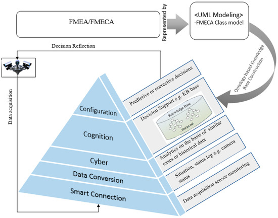
Figure 1.
Proposed framework to detect and prevent failure by using a knowledge base.
FMECA is composed of basic information: item/component, functions, failures, failure effects, the cause of the failure, current controls, severity, recommended actions, severity criticality, and other relevant details. FMECA also includes some other methods to assess the risk associated with the failures identified during safety analysis to prioritize the corrective measures. These methods include criticality analysis and Risk Priority Number (RPN) [39]. RPN is used to asses risk associated with identified failures. The RPN is usually calculated as follow:
where Severity is the estimation of the severity of the potential failure, Occurrence or likelihood is a numerical subjective estimate of the likelihood for each cause of failure, and Detection is the effectiveness of detecting the failure prior to failure occurrence. According to the standard MIL-STD-1629A [40], criticality analysis can be divided into two types: qualitative or quantitative. For quantitative analysis, the system engineers must define the reliability for each component and rate the probability of loss or severity that will emerge from each failure mode.
RPN = Severity × Occurrence × Detection
The Failure Mode Criticality (FMC) can be calculated as follows:
where β is the conditional probability of occurrence of upcoming higher failure effect, α represents the failure mode ratio, λp represents the part failure rate, and t is the time duration of the mission phase. The criticality for each item or component can be determined by the summation of all criticalities for each failure mode identified for each component or item. FMECA begins with the knowledge of failure modes of a component and addresses the effects of each failure on the system or sub-systems [38]. FMECA supports system engineers to check whether the components, with their identified failure modes, meet safety requirements. FMECA results may lead to accepting the proposed component, to suggesting recommendations for possible maintenance, or to demanding component replacement. Equations (1) and (2) are used to describe the potential failures in our KB because recommended actions are triggered based on the RPN and FMC of a failure.
FMC = βαλpt
In our proposed approach, we transformed the FMECA to a UML class diagram as shown in Figure 2 (FMECA class model in Figure 1). The model-based software development approach has already been used to help overcome various challenges regarding the development of CPS [31]. We used a model-based approach [41] to create a meta-model for FMECA. The main elements of FMECA are considered as classes during transformation. The essential relationship between these elements (classes) is defined as follows: a failure hasCause due to the occurrence of a causal factor, hasEffect on the whole CPS, hasMode to visible, hasType according to its severity, hasControlRules to detect, and has recommended actions that must be triggered to prevent the failure. The class diagram also includes a component. which has associated failures. The components have a location where they are spread.
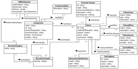
Figure 2.
FMECA modeling in UML class diagram.
The representation of the class diagram to the KB is performed using ontology. The ontology has object properties and data properties. The relationship description from the class diagram is used as object properties and the attributes of the class diagram are considered as data properties. Figure 3 shows an example of object property transformation, where the hasCriticality relationship from the class diagram (Figure 2) has been used as an object property, which has domain class Failure and class Component. Class SeverityCategory is the range of the hasCriticality object property. The attributes of the class have been used to form the data properties during ontology-based KB construction.
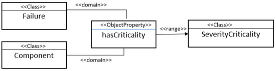
Figure 3.
UML representation of the class hasCriticality relationship.
4. Implementation of FMECA Class Model
Protégé [42] is a free and open-source framework to build intelligent systems. It is a tool that facilitates transposition of the FMECA class model into an ontology that is expressed in an equivalent XML-based format. The FMECA class metamodel is implemented in two steps.
4.1. Presenting Class Hierarchy
The UML classes of FMECA metamodel are expressed by protégé classes that have the exact same name and responsibility. The classes represented in Figure 2 are considered classes in protégé. Figure 4 shows the class hierarchy of our ontology in protégé. FMECASystem is the main class of the defined ontology, which consists of subclasses to identify and mitigate the identified failures. The subClassOf axiom type represents a subordination relationship between main class and its subclasses. The subclasses of FMECASystem are shown in Figure 4, where PotentialHazard, Component, ComponentData, ControleRule, Failure, FailureCause, FailureEffect, FailureMode, FailureType, RecommendedActions, SeverityCategory, and SeverityCriticality are presented as subclasses of FMECASystem.
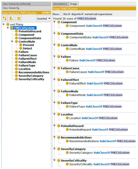
Figure 4.
Protégé representation of FMECA.
4.2. Data Property and Object Property Representation
The attributes of our UML class model for FMECA are expressed in protégé by type property. There are two types of properties in protégé: (1) Data Property, which elaborates the features offered by the respective class through various data types, and (2) Object Property is used to define the relationship between classes of UML class model of FMECA by mentioning domain and range. Figure 5 shows an example of datatype representation in protégé. For example, the hasName datatype of class FailureType, FailureMode, Component, FailureCause, FailureEffect, RecommendedActions, Failure, etc. is presented as data property in protégé. Figure 6 shows the representation of object properties in protégé. The reasoning outlined in Figure 3 is used to reflect the object properties in protégé. The object properties, which are called relations in UML, can be functional, inverse functional, transitive, symmetric, asymmetric, reflexive, or irreflexive [43]. These characteristics of object properties are used to help to analyze the failure in our study. For example, Figure 7 shows an example of the transitive property hasCause. The transitive property is used in cases such as: if subclass FailureMode has object property hasCause and subclass Component has object property hasMode related to subclass FailureCause, then subclass Component is inferred to have hasCause object property related to subclass FailureCause.
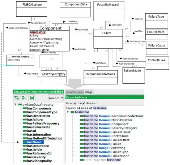
Figure 5.
Data property representation in protégé.
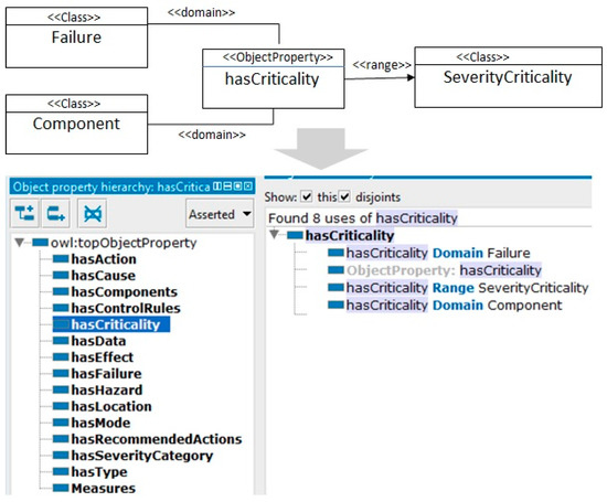
Figure 6.
Object property representation in protégé.
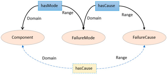
Figure 7.
Representation of the transitive rule of object property (hasCause).
5. Approach Validation
We chose a smart home case study to validate our proposed methodology. The smart home provides home security, convenience, comfort, and energy efficiency by controlling these aspects with smart devices. The smart home includes security cameras allowing residents to monitor their home when they are on vacation or away from their homes. For this purpose, we established a testbed, where we used an Intel Galileo Gen2 card [44] as the experimental platform. The XBee pro(S2B) [45] wireless communication, as the communication unit, and some off-the-shelf sensors for temperature, humidity, fire, rain, and carbon monoxide (CO) were installed to facilitate the inhabitants of a smart home. The temperature sensor was installed in a window to monitor the outside temperature to control the heating system of the home. The humidity sensor was also installed in a window to monitor the humidity and moisture in the air. The fire sensor was installed in the kitchen to prevent any fire incident in the home, while the CO sensors were installed in bedroom and lobby to record the concentration of CO in the home. When the concentration of CO crosses a defined limit, it generates an alarm and opens the home windows automatically. The rain sensors were installed in front of windows, which are used to close the windows in case of rain. The cameras were installed on the front main gate and the rear gate of the smart home to enable differentiation between visitors, pets, residents, and burglars. Figure 8 shows the general architecture of a smart home system.
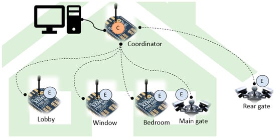
Figure 8.
General architecture of a smart home system.
In our testbed, each XBee module was configured through the XCTU [46] program. The XCTU is a free, multi-platform application compatible with windows, MacOS and Linux. Subsequently, the input pins were selected and activated through which the sensors were connected with each module. The data gathered by the sensor were sent to the coordinator XBee module. The coordinator XBee module transferred collected data from each sensor to serial communication on the Inter Galileo card, and it goes through the conversion layer of 5C architecture, where data are converted into information.
Six sensors were placed in five different places of the smart home including the lobby, windows, bedroom, main gate, and rear gate. For simplicity, we only monitored the data of CCTV cameras installed in front of the main gate and rear gate. In a smart home, the CCTV cameras monitor the environment and send information to the CPS continuously to assure the safety of the home. The CCTV cameras collect initial real-time data from the environment surrounding the main gate and rear gate. Therefore, parameters like video quality (Q) of a camera, the angle of rotation (Rt), time delay (T), and rotation speed (Sr) are recorded to monitor the performance of the installed cameras. The collected data were transmitted to the cyber layer through the conversion layer, where they are stored in a database. Using this data, system engineers would be able to estimate the life of the camera and measure the reliability of the camera. The cameras and other sensors were connected through the smart connection layer of CPS. To achieve availability, redundant cameras (CCTVCamera1, CCTVCamera2, and CCTVCamera3) were installed to cope with any potential failure. If CCTVCamera1 failed for any reason, the system would detect the failure and automatically activate either Camera 2 or 3 as an alternative. As mentioned above, we employed 5C architecture to design the smart home security system systematically. Considering that, the input of sensors had to go through a smart connection layer that deals with data acquisition and monitoring. Then, the data went through a data conversion layer, where the data were converted into information (how to convert data to information is beyond the scope of this paper).
Finally, information was stored in a database in cyber layer, which is also called the self-compare level, where it compares the current information from the sensor with similar cases or historical data of that sensor to predict the performance of the sensor and to predict the reliability of that sensor. Here, the failures can be identified, because it analyzes the data based on similar cases or compares it with the historical data. In our case, the cyber layer of 5C architecture has to maintain parameters such as Q, Rt, T, and Sr. Any difference among expected and actual values is considered as a fault and the next level of 5C architecture decides what to do if a fault occurs. Figure 9 shows an example of stored parameters in the cyber layer. The data are continuously stored with the time difference of 60 s. Then, the stored data are compared with previous similar data and failures are identified. As shown in Figure 9, the camera failure occurred due to stop rotation. At a specified time (6/06/18 10:06 p.m.), when the camera stopped its rotation, the system noticed that camera 1 could not update its value in the cyber layer. As a result, the system considered it as a null value and compared it with historical data of the same camera and determined that a fault occurred. Hence, the failure was identified.
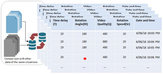
Figure 9.
Failure identification in cyber layer.
By analyzing the severity, RPN, and FMC of the identified failure, the recommended action(s) is/are taken in the cognition layer, where we already built an ontology-based KB using FMECA. Lastly, the actions were reflected dynamically in the configuration layer. For example, the cyber layer detected that CCTVCamera1 stopped rotation. Now, based on our KB, it has high severity; therefore, the system triggered the most appropriate recommended action (activate alternative) to mitigate the identified failure. As a result, the system configured itself to reflect the changed actions and activated CCTVCamera2. The system identified and prevented the potential failure of the system. We applied some dirt to the front face of Camera 2 to affect the video quality so that we would be able to test whether the system recognizes the poor quality. We noticed that the system detected CCTVCamera2′s video quality decreased gradually (detected in the cyber layer) and decided to generate a warning message for the human in the loop to examine the situation as soon as possible. All this was possible due to our KB. Figure 10 shows an example of a CCTVCamera1 individual of the class Component. The instances were created in our ontology to handle the failure or predicted failure.
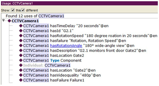
Figure 10.
Example of the CCTVCamera1 individual in protégé.
Figure 11 describes the instances of Failure and Component class. The arc types show the relationship among elements of an ontology. Each instance of a class or a subclass includes data properties and/or object properties. The CCTVCamera1 instance of Component class provides all the needed information, e.g., failure, the location of the failure, its identification, and a brief description. Another instance of the Failure class is Failure1 showing complete information. For example, Failure1 is caused due to power off, has mode to manifest, and has recommended actions that must be implemented in case of Failure1. The potential failures can be prevented by triggering the recommended actions. In this case, when CCTVCamera1 fails due to power failure, then the system detects it and activates an alternate camera to avoid the potential hazard. As such, each instance in ontology is enriched with enough knowledge to be described. This information can be used in a number of ways. For example, this information can be used to predict the lifespan of a camera. The sensor information is also used to purchase reliable and quality sensors in the future because the sensor data are stored in a database for future use.
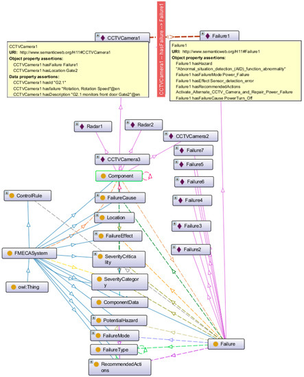
Figure 11.
Instances of Class Failure and Component in protégé ontology.
The system engineers can also use ontology-based KB to analyze the system. For analysis, SPARQL query [47] can be used. The result of the query can obtain information about system maintenance or detect the failure immediately. Figure 12 shows the query and its results. The query provides information about CCTVCamera3 including failure, failure mode, failure cause, severity, potential hazards, and control rules. Based on the severity of the intended failure, the recommended actions are undertaken.
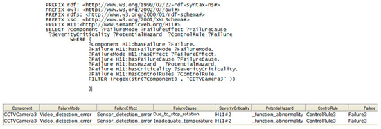
Figure 12.
SPARQL query to see CCTVCamera3 information.
Similarly, Figure 13 shows the query that returns recommended action for identified failures, including Failure3. The system recommended two types of actions. First, the system recognized the failure of the CCTVCamera1 due to power failure and configured itself to activate the alternate camera for the site monitoring in order to avoid potential hazards. The second action was the issuance of a notice to its operators or system engineers to repair the power failure. Therefore, Failure3 was prevented due to the recommended action that provided an alternative camera.
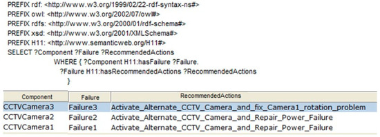
Figure 13.
SPARQL query for recommended actions for failures of CCTVCamera1, 2, and 3.
6. Conclusions
In this paper, we presented a failure identification and prevention approach using an ontology-based knowledge base. The KB was produced using the prominent hazard analysis technique FMECA, which manages potential failures of the system and also identifies failure cause, the effect of the failure, severity, and recommended actions to prevent or mitigate the potential failure. We transformed FMECA to a UML class diagram and then the UML class diagram was represented using protégé. For the systematic application of our proposed approach, we used the 5C architecture of smart industries. Lastly, the proposed approach was validated using a smart home case study.
However, there are some limitations of this research that need to be further investigated in the future. The ontology model in our proposed approach is relatively simple because it only incorporated FMECA for failure analysis. Therefore, we want to use more hazard analysis techniques, such as fault tree and event tree analysis, along with FMECA to enrich the KB to trace the failure in multiple CPS applications. The data reliability was not considered in this study, so it needs to be addressed in the future because sometimes inaccurate data itself leads to the failure of the system. Furthermore, we only fully investigated the camera sensor in detail, which is relatively simple, although we installed four other sensors in our case study testbed. More detail was intentionally avoided to focus on the specific research domain.
Author Contributions
N.A. proposed the failure detection and prevention framework by using FMECA to form a knowledge base. N.A. conducted the case study to validate the proposed approach. J.-E.H. supervised overall research and provided feedback and comments where necessary.
Funding
This research was supported by the NRF of Korea funded by the MSIT (NRF-2017M3C4A7066479).
Acknowledgments
We thank all members of our CPS project for their support.
Conflicts of Interest
The authors declare no conflict of interest.
References
- Nannapaneni, S.; Mahadevan, S.; Pradhan, S.; Dubey, A. Towards reliability-based decision making in cyber-physical systems. In Proceedings of the 2016 IEEE International Conference on Smart Computing (SMARTCOMP), St. Louis, MO, USA, 18–20 May 2016; pp. 1–6. [Google Scholar] [CrossRef]
- Törngren, M.; Asplund, F.; Bensalem, S.; McDermid, J.; Passerone, R.; Pfeifer, H.; Sangiovanni-Vincentelli, A.; Schätz, B. Characterization, analysis, and recommendations for exploiting the opportunities of cyber-physical systems. In Cyber-Physical Systems; Elsevier Academic Press: Cambridge, MA, USA, 2017; pp. 1–14. [Google Scholar]
- Ghimire, S. Self-Evolutionary Cyber Physical Systems: Leap towards Smart CPS. Ph.D. Thesis, Universidade NOVA de Lisboa, Lisbon, Portugal, December 2016. [Google Scholar]
- NIST. Strategic R&D Opportunities for 21st Century Cyber-Physical Systems. Available online: http://www.nist.gov/el/upload/12-Cyber-Physical-Systems020113_final.pdf (accessed on 12 April 2018).
- Kabashkin, I.; Kundler, J. Reliability of Sensor Nodes in Wireless Sensor Networks of Cyber Physical Systems. Procedia Comput. Sci. 2017, 104, 380–384. [Google Scholar] [CrossRef]
- Sanislav, T.; Zeadally, S.; Mois, G.; Fouchal, H. Multi-agent architecture for reliable Cyber-Physical Systems (CPS). In Proceedings of the 2017 IEEE Symposium on Computers and Communications (ISCC), Heraklion, Greece, 3–6 July 2017; pp. 170–175. [Google Scholar] [CrossRef]
- Sanislav, T.; Zeadally, S.; Mois, G.D.; Fouchal, H. Reliability, failure detection and prevention in cyber-physical systems (CPSs) with agents. Concurr. Comput. Pract. Exp. 2018, e4481. [Google Scholar] [CrossRef]
- Nuñez, D.L.; Borsato, M. An ontology-based model for prognostics and health management of machines. J. Ind. Inf. Integr. 2017, 6, 33–46. [Google Scholar]
- Lee, J.; Bagheri, B.; Kao, H.A. A cyber-physical systems architecture for industry 4.0-based manufacturing systems. Manuf. Lett. 2015, 3, 18–23. [Google Scholar] [CrossRef]
- Kalaycı, İ.; Ercan, T. A framework model for data reliability in wireless sensor networks. In Proceedings of the Signal Processing and Communication Application Conference (SIU), Zonguldak, Turkey, 16–19 May 2016; pp. 1793–1796. [Google Scholar] [CrossRef]
- Jiang, W.; Zhuang, M.; Xie, C. A reliability-based method to sensor data fusion. Sensors 2017, 17, 1575. [Google Scholar] [CrossRef] [PubMed]
- Yuan, K.; Xiao, F.; Fei, L.; Kang, B.; Deng, Y. Modeling sensor reliability in fault diagnosis based on evidence theory. Sensors 2016, 16, 113. [Google Scholar] [CrossRef] [PubMed]
- Ahmadi, A.; Cherifi, C.; Cheutet, V.; Ouzrout, Y. A review of CPS 5 components architecture for manufacturing based on standards. In Proceedings of the SKIMA, International Conference on Software, Knowledge, Intelligent Management and Applications, Malabe, Sri Lanka, 6–8 December 2017. [Google Scholar]
- Lee, J.; Jin, C.; Liu, Z. Predictive big data analytics and cyber physical systems for TES systems. In Advances in Through-life Engineering Services; Springer: Cham, Switzerland, 2017; pp. 97–112. [Google Scholar]
- Kao, H.A.; Jin, W.; Siegel, D.; Lee, J. A cyber physical interface for automation systems—Methodology and examples. Machines 2015, 3, 93–106. [Google Scholar] [CrossRef]
- Brank, J.; Grobelnik, M.; Mladenić, D. A survey of ontology evaluation techniques. In Proceedings of the 8th International Multi-Conference Information Society, Ljubljana, Slovenia, 10–17 October 2005. [Google Scholar]
- Uschold, M.; King, M. Towards a methodology for building ontologies. 1995. Available online: http://www.aiai.ed.ac.uk/publications/documents/1995/95-ont-ijcai95-ont-method.pdf (accessed on 6 December 2018).
- Grüninger, M.; Fox, M.S. Methodology for the design and evaluation of ontologies. In Proceedings of the Workshop on Basic Ontological Issues in Knowledge Sharing, Montreal, QC, USA, 13 April 1995. [Google Scholar]
- López, M.F.; Gómez-Pérez, A.; Sierra, J.P.; Sierra, A.P. Building a chemical ontology using methontology and the ontology design environment. IEEE Intell. Syst. Their Appl. 1999, 14, 37–46. [Google Scholar] [CrossRef]
- Kozaki, K.; Kitamura, Y.; Mizoguchi, R. Developing Ontology-based Applications using Hozo. In Proceedings of the International Conference on Computational Intelligence, Alberta, Canada, 4–6 July 2005; pp. 273–277. [Google Scholar]
- Sure, Y.; Angele, J.; Staab, S. OntoEdit: Guiding ontology development by methodology and inferencing. In OTM Confederated International Conferences on the Move to Meaningful Internet Systems; Springer: Berlin/Heidelberg, Germany, 2002; pp. 1205–1222. [Google Scholar]
- García-Peñalvo, F.J.; Colomo-Palacios, R.; García, J.; Therón, R. Towards an ontology modeling tool. A validation in software engineering scenarios. Expert Syst. Appl. 2012, 39, 11468–11478. [Google Scholar] [CrossRef]
- Zhou, J.; Hänninen, K.; Lundqvist, K.; Provenzano, L. An ontological interpretation of the hazard concept for safety-critical systems. In Proceedings of the 27th European Safety and Reliability Conference ESREL’17, Portoroz, Slovenia, 18–22 June 2017; pp. 183–185. [Google Scholar]
- Zhou, J.; Hänninen, K.; Lundqvist, K.; Provenzano, L. An ontological approach to hazard identification for safety-critical systems. In Proceedings of the 2017 Second International Conference on Reliability Systems Engineering (ICRSE), Beijing, China, 10–12 July 2017; pp. 1–7. [Google Scholar] [CrossRef]
- Zhou, J.; Hänninen, K.; Lundqvist, K.; Provenzano, L. An ontological approach to identify the causes of hazards for safety-critical systems. In Proceedings of the 2017 2nd International Conference on System Reliability and Safety (ICSRS), Milan, Italy, 20–22 December 2017; pp. 405–413. [Google Scholar] [CrossRef]
- Sanislav, T.; Mois, G. A dependability analysis model in the context of cyber-physical systems. In Proceedings of the 2017 18th International Carpathian Control Conference (ICCC), Sinaia, Romania, 28–31 May 2017; pp. 146–150. [Google Scholar] [CrossRef]
- Zhao, X.; Zhu, Y. Research of fmea knowledge sharing method based on ontology and the application in manufacturing process. In Proceedings of the 2010 2nd International Workshop on Database Technology and Applications (DBTA), Wuhan, China, 27–28 November 2010; pp. 1–4. [Google Scholar] [CrossRef]
- Zhao, L.; Ichise, R.; Sasaki, Y.; Liu, Z.; Yoshikawa, T. Fast decision making using ontology-based knowledge base. In Proceedings of the Intelligent Vehicles Symposium (IV), Gothenburg, Sweden, 19–22 June 2016; pp. 173–178. [Google Scholar] [CrossRef]
- Sureephong, P.; Chakpitak, N.; Ouzrout, Y.; Bouras, A. An ontology-based knowledge management system for industry clusters. In Global Design to Gain a Competitive Edge; Springer: London, UK, 2008; pp. 333–342. [Google Scholar]
- Sadik, A.R.; Urban, B. An Ontology-Based Approach to Enable Knowledge Representation and Reasoning in Worker–Cobot Agile Manufacturing. Future Internet 2017, 9, 90. [Google Scholar] [CrossRef]
- Törsleff, S.; Hildebrandt, C.; Daun, M.; Brings, J.; Fay, A. Developing Ontologies for the Collaboration of Cyber-Physical Systems: Requirements and Solution Approach. In Proceedings of the 2018 4th International Workshop on Emerging Ideas and Trends in the Engineering of Cyber-Physical Systems (EITEC), Porto, Portugal, 11 April 2018; pp. 25–32. [Google Scholar]
- Petnga, L.; Austin, M. An ontological framework for knowledge modeling and decision support in cyber-physical systems. Adv. Eng. Inform. 2016, 30, 77–94. [Google Scholar] [CrossRef]
- Coelhoa, M.; Austina, M.A.; Blackburnb, M.R. The Data-Ontology-Rule Footing: A Building Block for Knowledge-based Development and Event-driven Execution of Multi-Domain Systems. In Proceedings of the CSER 2018 16th Annual Conference on System Engineering Research, Charlottesville, VA, USA, 8–9 May 2018. [Google Scholar]
- Xu, F.; Liu, X.; Chen, W.; Zhou, C.; Cao, B. Ontology-Based Method for Fault Diagnosis of Loaders. Sensors 2018, 18, 729. [Google Scholar] [CrossRef] [PubMed]
- Maleki, E.; Belkadi, F.; Ritou, M.; Bernard, A. A Tailored Ontology Supporting Sensor Implementation for the Maintenance of Industrial Machines. Sensors 2017, 17, 2063. [Google Scholar] [CrossRef] [PubMed]
- González, E.; Marichal, R.; Hamilton, A. Software Experience for an Ontologybased Approach for the Definition of Alarms in Geographical Sensor Systems. IEEE Access 2018, 6, 55556–55572. [Google Scholar] [CrossRef]
- Alirezaie, M.; Renoux, J.; Köckemann, U.; Kristoffersson, A.; Karlsson, L.; Blomqvist, E.; Tsiftes, N.; Voigt, T.; Loutfi, A. An ontology-based context-aware system for smart homes: E-care@ home. Sensors 2017, 17, 1586. [Google Scholar] [CrossRef] [PubMed]
- Bouti, A.; Kadi, D.A. A state-of-the-art review of FMEA/FMECA. Int. J. Reliab. Qual. Saf. Eng. 1994, 1, 515–543. [Google Scholar] [CrossRef]
- FMEA-FMECA. Available online: http://www.fmea-fmeca.com/fmea-rpn.html (accessed on 6 December 2018).
- MIL-STD-1629. Available online: http://www.fmea-fmeca.com/milstd1629.pdf (accessed on 6 December 2018).
- ISO. Systems and Software Engineering–Architecture Description; ISO/IEC/IEEE 42010; IEEE: Piscataway, NJ, USA, 2011; pp. 1–46. [Google Scholar]
- Protégé 5.0. Available online: https://protege.stanford.edu/ (accessed on 6 December 2018).
- Horridge, M.; Jupp, S.; Moulton, G.; Rector, A.; Stevens, R.; Wroe, C. A practical guide to building owl ontologies using protégé 4 and co-ode tools edition 1.3. Available online: http://mowl-power.cs.man.ac.uk/protegeowltutorial/resources/ProtegeOWLTutorialP4_v1_3.pdf (accessed on 6 December 2018).
- Getting Started with the Intel® Galileo Board on Windows. Available online: https://software.intel.com/en-us/get-started-galileo-windows (accessed on 6 December 2018).
- Digi XBee/XBee-PRO ZigBee Modules (S2B)-Formerly ZB. Available online: https://www.digi.com/support/productdetail?pid=4549 (accessed on 6 December 2018).
- Next Generation Configuration Platform for XBee/RF Solutions. Available online: https://www.digi.com/products/xbee-rf-solutions/xctu-software/xctu (accessed on 6 December 2018).
- SPARQL Query Language for RDF. Available online: https://www.w3.org/TR/rdf-sparql-query/ (accessed on 5 December 2018).


© 2018 by the authors. Licensee MDPI, Basel, Switzerland. This article is an open access article distributed under the terms and conditions of the Creative Commons Attribution (CC BY) license (http://creativecommons.org/licenses/by/4.0/).