Abstract
This article addresses a critical security challenge in Internet of Things (IoT) systems, which are vulnerable to traffic detection attacks due to their reliance on shared wireless communication channels. We propose a novel cooperative covert transmission strategy to enhance the security of IoT communications against these attacks through the implementation of physical-layer security mechanisms. Inspired by zero-forcing precoding techniques, the proposed approach enables cooperation between different IoT devices in the system to increase the likelihood of adversaries making incorrect conclusions about the communication activity of the targeted IoT device. The proposed covert communication strategy complements traditional security measures, provides a scalable solution, and is suitable for resource-constrained IoT environments. The numerical results in this article demonstrate significant improvements in protecting communications against traffic detection attacks, which contributes to the overall security and privacy of IoT systems.
1. Introduction
The Internet of Things (IoT) refers to network-connected devices that are equipped with sensors and/or actuators. These devices collect and transmit data for facilitating automation and improved decision-making, and they enable efficient monitoring, control, and optimization of processes with minimal human intervention. The integration of IoT systems extends across numerous industries, and it demonstrates the potential of large-scale deployments which are supported by machine-to-machine communication links. As IoT continues to grow, information security concerns have emerged [1,2].
Information security is a crucial aspect of IoT systems because of their widespread use and the sensitive nature of the data they could handle. Ensuring the confidentiality of information means protecting it from unauthorized access, integrity involves safeguarding data from unauthorized modification, and information availability ensures that data is accessible when needed. IoT systems are particularly vulnerable due to their reliance on shared wireless communication channels, which makes them susceptible to various security threats. These threats could potentially be serious because of the limited computational resources of many IoT devices that often lack the capacity to implement robust traditional security measures.
Traffic detection attacks occur when malicious actors passively listen to and analyze network traffic and communication patterns to gather information about devices, users, or systems, without active attempts to breach security [3,4,5,6]. In IoT environments, traffic detection attacks pose security risks because of the often limited security capabilities of IoT devices and the critical nature of the data they handle. Many IoT devices operate with constrained resources and may lack robust encryption or other security features, which makes them easy targets for monitoring by attackers [7,8].
The implications of a successful traffic detection attack on IoT systems can be severe because it may reveal patterns in device communication and indicate the operational status or sensitive activities. For example, in a smart home setting, a malicious actor could deduce when the occupants are home or away based on the traffic generated by home’s IoT devices such as smart locks, lights, or cameras. In industrial IoT environments, traffic detection attacks could expose the operational schedules and control signals of critical infrastructure, which potentially leads to targeted disruptions or sabotage. Therefore, the presence of such attacks emphasizes the need for robust security measures in IoT ecosystems and highlights the importance of traffic obfuscation, strong encryption, vigilant network monitoring, and covert modes of communicating over the channel.
This article explores a paradigm shift in the employment of covert communication techniques to mitigate traffic detection attacks that target IoT environments. Covert communications represent an innovative security approach to improve information confidentiality and mitigate traffic detection attacks [9,10]. Covert communications involve the transmission or exchange of information in a concealed manner to avoid detection or interception by unauthorized parties [11]. Various techniques can be employed to hide the existence or content of communications, which includes steganography, encryption, and the use of covert channels.
In this article, we leverage physical-layer security concepts [12,13,14,15] to develop an IoT transmission scheme that limits the ability of adversaries to detect the presence or the absence of signal transmissions over the channel through calculated precoding weights. We propose a cooperative covert transmission strategy that allows different IoT units to participate in order to increase the likelihood of the adversary drawing wrong conclusions about whether a targeted IoT is actively communicating over the channel or is idle. This approach aims to complement existing security measures, offering robust and scalable solutions to the growing security challenges in IoT systems.
The rest of this article is organized as follows. A background about traffic detection attacks and covert communications is provided in Section 2. The system model and the traffic detection problem setup are introduced in Section 3. The objectives of covert communication against the traffic detection adversaries are developed in Section 4. The covert defense strategy against these attacks is formulated in Section 5. Numerical results that support the analytical development are shown in Section 6. Finally, Section 7 and Section 8 conclude the article with discussions and conclusions.
2. Covert Communications Against Traffic Detection Attacks
In wireless communications, traffic detection attacks involve the monitoring of the radio frequency spectrum to identify the presence of ongoing transmissions. These attacks differ from more invasive attacks because they do not seek to decrypt the content of the communication. Instead, traffic detection focuses on gathering metadata, such as the timing, duration, and frequency of the transmissions. This information can reveal sensitive details about the communication patterns and behaviors of the users or devices which are involved. For example, an attacker could deduce the existence of a conversation or data transfer between specific nodes, even if the actual data remains encrypted. This stage often serves as a precursor to more targeted attacks because it provides the attacker with critical intelligence about when and where to focus their efforts for maximum impact.
Several tools and techniques can be employed to mitigate traffic detection attacks [16,17,18]. One common approach is frequency hopping, in which the communication frequency changes rapidly according to a predefined sequence and this makes it harder for an attacker to follow the transmission. Another method is spread spectrum, which spreads the signal over a wider bandwidth than necessary and this makes it less visible. Encryption also plays a crucial role because it secures the content and obscures metadata such as packet length and timing. Traffic padding can help thwart analysis attempts because it adds dummy data to make traffic patterns less distinguishable. In addition, directional antennas and beamforming can reduce the chances of traffic detection because they focus the signal in a specific direction and limit its exposure to unintended receivers.
Covert communication refers to the transmission of hidden or concealed information [19,20,21]. One covert approach involves spread spectrum techniques that spread the communication signal across a wide frequency band, which makes it difficult to detect or intercept. Covert channels in wireless protocols can also be exploited to establish hidden communication paths. For example, unused or reserved fields within wireless protocol headers can be utilized to transmit covert information without raising suspicion. Low power transmission is also a useful technique for covert communication because it transmits signals at extremely low power levels, which minimizes the chances of detection by unauthorized individuals or surveillance systems. The low power levels make the signal harder to intercept and decipher. Burst transmissions involve the transmission of short bursts of data or information intermittently, which reduces the chances of detection and makes it challenging to trace the source. This method is used because it minimizes the time during which the transmission occurs.
Academic interest in covert communication has been increasing in recent years [22,23,24,25,26,27,28,29,30]. The work of [22] discusses elementary results on the use of friendly jammers to facilitate a coordinated covert communication scheme between a transmitter and a receiver in additive white Gaussian noise (AWGN) channels. Hiding transmission activity is also discussed in [23] as a means to achieve covertness through interference from cooperative jamming from background noise, artificial noise from friendly nodes, or aggregated interference sources. The work of [24] analyzes the average covert probability and the covert throughput of the system when subjected to a Poisson field of interferers, where all nodes in the system randomly transmit without the intention to help in hiding the communication, resulting in an aggregate received interference at the receiver modeled as a shot noise. Further, communication covertness is proposed in [25] to be achieved by using a full-duplex receiver, where the legitimate receiver generates artificial noise with a varying power to create uncertainty at the adversary regarding the received signal’s level at the adversary’s side.
The use of friendly randomly distributed jammers is considered in [26] to collaboratively target the adversary through producing artificial noise to enhance the covertness of the communication. In addition, a covert communication scheme is considered in [27] for a relay network, where the relay uses a two-relay beamforming scheme to transmit its own messages covertly to a destination node when relaying the source’s transmission without the knowledge of the source node. A cooperative deception strategy is also proposed in [28] for covert communication in the presence of a multi-antenna adversary, where jammers solve an optimization problem for covert rate maximization in order to degrade the reception ability of the adversary and achieve a covert transmission rate. Further, the work of [29] considers an approach to counter detection and eavesdropping attacks using artificial noise and power control schemes, and develops a covert secrecy rate metric to account for requirements related to overtness, secrecy, and transmission performance. Also, covert communication is considered in [30] as an enabler for non-terrestrial networks in 6G systems.
Clear gaps in the recent research include: not considering the transmission state of the targeted device; for example, the aforementioned works only try to hide the transmission activity of the device while the idle mode is not considered. Furthermore, to degrade the reception ability of the adversary, friendly devices in the system are used as active jammers, which could be considered as wasteful. In addition, requiring the relays or the adversaries to have multi antennas, needing the jammers to be in a close proximity to the adversary, or having a full-duplex receiver are restrictive requirements.
Given the aforementioned challenges, a new approach to achieving covert communications is warranted, especially for environments where there are multiple transmitters that are available to cooperate. Following a physical-layer security approach similar to that in [31,32], the covert strategy considers generic devices without any constraints on their number of antennas, their proximity to the adversary, or their full-duplex transmission capabilities. The proposed scheme compensates the cooperating devices by allowing them to communicate their data over the channel. In addition, the proposed covert scheme has an algorithmic representation to facilitate practical implementations.
In the following sections, we propose a cooperative covert transmission strategy that takes advantage of the channel conditions to mitigate the impact of a traffic detection attack that targets a specific IoT device. The objective of the proposed strategy is to confuse the adversary into making incorrect conclusions about the transmission state of the targeted device. The developed transmission strategy provides mitigation to both active and idle states of the targeted device and allows other devices to cooperate while not wasting transmission power.
3. System Model
A layered defense strategy can be used to enhance the security of IoT systems since it employs multiple security defenses to protect a system and make it more resilient to attacks [33]. On the other hand, physical-layer security leverages the physical properties of communication channels to further enhance the security of data in motion; these techniques can also be integrated into the layered defense strategy [34]. Ensuring information confidentiality in IoT communications is critical, particularly because IoT systems are increasingly integrated into vital industrial processes and control operations, for the prevention of unauthorized access to sensor measurements and commands that are exchanged between legitimate system devices. This prevention is essential to IoT systems because it protects against data breaches, which could lead to intellectual property theft, privacy violations, or reverse engineering of system settings. The value and functionality of IoT devices can be significantly impacted when their security is compromised, which emphasizes the importance of robust confidentiality and traffic obscurity measures.
3.1. IoT Environment
Consider the case of an IoT environment where there are multiple IoT devices that want to communicate their data over the wireless channel to the respective receivers. Assume the existence of an adversary that is interested in passively detecting the presence or the absence of signal transmission of a specific IoT device (i.e., wants to conduct a traffic detection attack) against a targeted IoT device). Let the under-attack IoT be called the primary IoT unit (PU); also, let the other IoT devices in the system be collectively termed the secondary unit (SU), and let the adversary device be called the adversary unit (AU), as shown in Figure 1. For generic analysis, let the respective receivers be collectively called the receiver unit (RU).
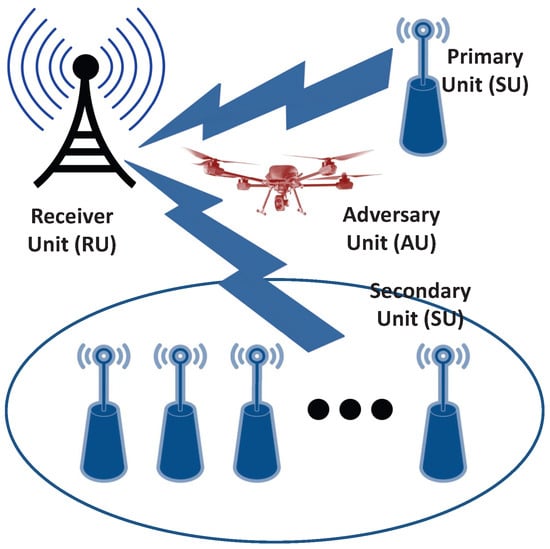
Figure 1.
Covert defense setup.
In this environment, SU is willing to cooperate with PU to conduct covert communication against AU and mislead AU about the transmission state of PU; as a compensation for this cooperation, SU receives extra transmission time to communicate its own data. The assumptions used in the following analysis are:
- Channel gains and transmission powers are known to PU and SU.
- AU is synchronized to PU’s bit and packet transmission.
- SU will cooperate with PU in order to deceive AU and make it make more incorrect conclusions about whether PU is communicating or not.
The described environment in Figure 1 includes PU and SU as IoT devices, AU as the adversary that is interested in determining the existence or the absence of PU’s transmission, and RU as the intended receiver of PU’s wireless transmission. Let the channels between the transmitters (PU and SU) and receivers (RU and AU) be Rayleigh block fading channels with channel gains termed as from PU to RU, from PU to AU, from SU to RU, and from SU to AU as shown in Figure 2. The receivers are also corrupted with AWGN signals. The noise signal at RU (denoted as ) has a zero mean and a variance of ; further, AU is corrupted with an AWGN signal (called ) of zero mean and a variance of .
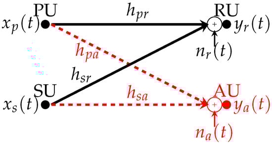
Figure 2.
Environment model.
Let the data signal from PU be denoted , and that of SU be called . The primary and secondary data signals are assumed to be binary with a unity average power. Further, assume that PU transmits its signal with a power of and that SU uses to transmit its own signal. In addition, let and be the maximum allowed transmission power of PU and SU, respectively; i.e., and . Finally, let the received signal at RU be called and the received signal at AU be termed . Ignoring the propagation delay between the transmitters and the receivers and given the aforementioned notation, the received signals at time t at RU and AU are given by
3.2. Traffic Detection Problem Setup
Recall that AU is interested in determining whether PU is active or idle on the wireless channel; to do that, AU will take measurements of the received signal at its end and determine whether the received signal is a data packet or just noise. Assuming that there is no secondary transmission and that only PU could be active over the channel without cooperative transmission from SU, if PU is idle at time t, then the received signal at AU is a noise signal ; however, if PU is active at that time, then AU receives .
Let AU take samples of , termed as , where , and then calculate the average power of the samples as
The objective of AU is to decide from the value whether PU is active or idle in the current interval by comparing with a detection threshold, termed . Specifically, AU will conclude that the current packet is noise (and that PU is idle) if ; however, if , AU will conclude that PU is active over the channel. If PU is idle, then has a mean of . However, if contains data, the mean of is .
Taking a heuristic approach, a midpoint value between the two means can be used by AU as a decision point to determine whether PU is active or idle as
The approximation can be utilized for high signal-to-noise ratio (SNR) (i.e., low values of noise power). Thus, the decision criteria used by AU during its traffic detection attack against PU will be
4. Covert Communication Problem Formulation
PU can be thought to be in two states when it comes to its communication activity: active when it is communicating over the channel, and idle otherwise. When PU is active, it wants to conceal its communication activity and appear as idle to AU. On the other hand, when PU is idle and is not transmitting over the channel, it needs the channel at AU to show a communication activity. This way, AU will be more likely to make incorrect conclusions about PU’s communication state, which will lead to mitigating AU’s traffic detection attack on PU.
In order to achieve both objectives, SU will cooperate with PU to limit AU’s ability to correctly detect PU’s actual activity. When PU is active, SU will concurrently communicate over the channel to cause destructive interference at AU and make the received signal appear as noise-like; thus, AU will more probably mischaracterize PU’s activity as idle. Further, when PU is actually idle, SU will communicate its own signals, and AU will detect a communication activity which leads it to believe that PU is actually active over the channel. In general, not every SU in the system can fulfill these objectives. Thus, in the following, we derive secondary channel limits that need to be satisfied in order for SU to be able to effectively participate in this covert communication and achieve its goal in mitigating the traffic detection attack on PU.
4.1. Covert Communications Defense
In the following, we borrow from the zero-forcing precoding concepts [35] to develop the foundations of the cooperative strategy when PU is active. On the other hand, the strategy when PU is idle is developed in Section 5. Dropping the time symbol t, the ultimate objective of the covert transmission algorithm when PU is active is to design precoding weights such that:
- Objective 1:
- The signal from PU is preserved while canceling SU’s signal at RU; i.e., .
- Objective 2:
- Both signals from PU and SU are canceled at AU; thus, .
To get closer to this objective, we propose to augment PU’s and SU’s transmissions with precoding weights and , respectively, where and are to be determined. This makes the transmitted signal of PU as and that of SU as . In this case, the received signals at RU and AU are given by
Recalling the design objectives to decimate the transmitted signals at AU while preserving PU’s signal at its intended receiver, these objectives can be stated as
These requirements can be written in matrix form as
The solution to (7) is given by
This leads to finding the values of the primary and secondary precoding weights as
and
However, since SU does not a priori know the value of , SU cannot use it in constructing ; thus, as a workaround, let
The choice of in (9) and in (10) changes the received signal at RU as
or
This can be further simplified to
This results indicates that if it happens that , which randomly occurs of the time, the first design objective is satisfied; however, for the other of the time, when , there is a mismatch between the desired result and the actual signal value, and its magnitude should be as close as possible to unity in order to minimize the impact of this mismatch on the received signal at RU when PU is in the active mode.
Similarly, with the aforementioned choice of precoding weights, the received signal at AU can be described by
This formulation can be simplified to
Again, the second design objective is satisfied of the time, while there is a mismatch that occurs when half of the time. The magnitude of this mismatch should be made as small as possible in order to minimize the power measured at AU when PU is active.
4.2. Design Objectives
Considering the scenario of independent and random primary and secondary data transmissions, 50% of the time, and the received signal at RU in (13) matches the aspired first objective; on the other hand, 50% of the time, the received signal at RU deviates from that objective. The same observations can be drawn about the received signal at AU in (15). Define the mismatch at RU at (13) as , and define the mismatch at AU in (15) as .
Our goal now is to bound those mismatches in order to have maximum or minimum limits on the deviation cases (which randomly occur 50% of the time). Specifically, we want to limit the mismatch’s magnitude at RU to , where ; this bound ensures that the received power at RU exceeds . Similarly, the magnitude of the mismatch at AU is required to be bounded as , where . In this approach, we want to limit the deviation away from zero at AU to be bounded to and restrict the power of the measured signal at AU when PU is active to an upper bound of .
Recall that the transmitted power of PU’s signal has to be bounded by , and that of SU is bounded to . This implies that ; utilizing the definition of in (9) leads to . Also, using and the expression of in (10) gives .
During the active mode of PU, the objective of the cooperative covert communication algorithm is to find a secondary unit SU with channel gains and that satisfy the following design constraints:
where are the mismatch limits at AU and RU, and , , , and are complex Gaussian random variables that represent the channel gains. We aim to determine the limits on the secondary channel gains ( and ) to meet the constraints in (16) for specific values of , , , , , , , and .
Let , , and ; thus, the denominators in the four constraints in (16) become . We rewrite each constraint in terms of a and b as
Simplifying this formulation leads to
Combining the four constraints into one brings the constraints on secondary channel gains to
The covert algorithm needs to check whether SU has channel gains ( and ) that meet the requirements in (19) before being allowed to participate in the covert defense scheme and mitigate the traffic detection attack of AU on PU.
The objectives of (19) can be further approximated in the case of , , and to
This leads to further simplification of the constraints on the channel gains as
Employing the values of , , and leads to constraining the channel gains of SU as
This constraint can be restructured as
Combining the secondary channel gains and rearranging the terms leads to
This result combines the secondary channel gain requirements with the bounds on the received signals mismatch along with the primary channel gains. Also, since , which implies the secondary channels ratio does not exceed that of the primary channels; i.e.,
5. Covert Defense Strategy
As PU is under traffic detection attack by AU, both PU and SU adopt a cooperative defense strategy to help PU conduct a covert communication and limit AU’s ability to detect the presence or the absence of PU’s communication. The development in (19) indicates the conditions needed for the secondary channels in order to meet the design objectives when PU is active. Furthermore, the requirements of SU during PU’s idle mode will be derived in this section.
Recall that the adversary is interested in successfully detecting the transmission and the absence of the transmission of the primary IoT device. In order to do that, AU conducts a traffic detection attack. As detailed in Section 3, the adversary takes measurements in every transmission interval and decides whether , where is the average power of the samples as shown in (2) and is defined in (3) as the detection threshold.
Also, recall that PU goes into two communication modes: active mode, where it is actually transmitting its data to the primary receiver unit, and an idle mode, where it is not communicating over the channel. The primary IoT is interested in tricking the adversary device by increasing the likelihood that the adversary will interpret the measured signals incorrectly. PU is aided in this covert communication mission by secondary IoTs who want to participate in this scheme in exchange of getting the chance to communicate their own signals to their own receiver units when PU is idle.
When PU and SU are engaged in a covert communication activity during the active mode of PU, both PU and SU are active on the channel as long as SU meets the channel constraints of (16). In this case, the received signal at AU will be a noise signal 50% of the time, and for the other 50%, the signal at AU will be bounded by . Thus, the average received power at AU, , will be no more than . In order to deceive AU, PU needs this average power to be lower than the threshold that is used by AU in (3) to determine whether there is a primary transmission or not; this way, the adversary makes an incorrect conclusion that PU is idle. In other words, in order to conduct a covert communication while being active, PU needs
This result implies that
is required during PU’s active mode.
Similarly, When PU is idle, SU will be active alone over the channel. This means, the received signal at AU will be
Note that SU does not need to use precoding weights during this phase since it is the only device using the channel at that time. The average received power at AU in this phase will be . In order to confuse the adversary into believing that PU is active, the received power during this phase has to be no less than . Thus, given (3), the secondary power is bounded by
This constraint is required in order to increase the likelihood of AU concluding that PU is active while it is actually idle.
Let N be the number of secondary units in the system. The covert transmission strategy will schedule only one SU that meets the constraints in (16) and (29) in order to aid PU in achieving covert communications against AU’s traffic detection attack. In exchange for aiding PU in this endeavor, SU gets to transmit its data over the channel during PU’s idle mode. Recall that when PU is in active mode, both SU and PU cooperate through the use of precoding weights in order to limit the average power received by AU. On the other hand, when PU is in idle mode, only SU uses the channel to send its data; thus, confusing AU that there is a communication happening at that interval. The covert transmission strategy is detailed in Algorithm 1.
| Algorithm 1: Covert transmission strategy |
|
At first, the primary unit’s parameters ( and ), primary channel’s strengths ( and ), and noise power () are determined, the detection threshold used by the adversary () is estimated, and the mismatch thresholds ( and ) are assigned. Next, in a round-robin fashion, the covert algorithm checks every available SU out of the N secondary units in the system. For a secondary unit under consideration, the secondary channel strengths and device parameters are determined, then the design constraints in (16) are verified.
If a match that meets the constraints is found, PU will split its transmission duration into active mode (say, of the time, where ) and idle mode ( of the time). This indicates that SU can participate during PU’s active mode and can communicate alone during PU’s idle phase. During the active mode, the precoding weights of and are calculated as described in (9) and (10), respectively, and PU transmits its data as and SU uses . However, when PU goes into the idle mode, SU transmits its data as . If the current SU has no more data to communicate, the covert algorithm moves on to verify the next secondary unit on the list, and so on. The algorithm concludes when AU stops its traffic detection attack against PU or when PU no longer wants to achieve covert communications; this could be the case, for example, when PU has no more data to transmit over the channel.
6. Numerical Results
In this section we demonstrate the efficacy of the covert communication scheme through representative numerical examples. Specifically, we focus on numerically finding the algorithm’s success rate, which is a measure of the percentage of cases that the four conditions of (16) are satisfied in a randomized Monte Carlo simulation.
Scatter plots and histogram for the channel gains are shown in Figure 3 and Figure 4. For these figures, the values , , , and are used, the values of , , , and are randomly generated following Rayleigh distribution, and the channel strength values that meet the four constraints in (16) are recorded for these figures.
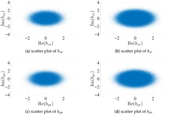
Figure 3.
Scatter of channel gains.
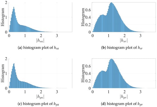
Figure 4.
Histogram of channel gains.
Observe the wider shapes in the scatter plots of and , indicating the higher frequency of high channel gain values that meet the requirements of (16) for these channels. On the other hand, the other two channels ( and ) have higher concentrations of smaller values. These observations translate to more widespread histograms for and , while the histograms of and show concentration towards to the left. The duality between the channels of PU and SU toward RU and AU is noted in these results as the scheduling algorithm favors secondary units with stronger channels with the legitimate receiver unit while having weaker ones with the adversary as indicated in (24), where is shown to be upper-bounded; similarly, decreasing or increasing leads to similar behavior to decreasing in (24). While the results for and and for and in Figure 3 and Figure 4 look similar, they are not identical.
In Figure 5, we study the impact of and on the success rate of the covert communication algorithm for and . Recall that provides a lower bound of the mismatch away from unity for the measured signals at RU during PU’s active mode; similarly, is the intended upper bound on the mismatch away from zero of the received signal at AU.
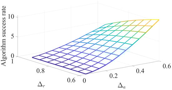
Figure 5.
Impact of and on the algorithm success rate.
The figure indicates that increasing the flexibility of the mismatch bounds (i.e., having higher values of or lower values of ) leads to better chances of identifying secondary units that meet the constraints of (16). Note that in (23), when the value of increases and/or when the value of is decreased, the margin of valid values of secondary channel gains expands. This leads to having better chances of identifying secondary units that satisfy the algorithm constraints, leading to higher algorithm success rates.
The impact of and on the algorithm success rate is demonstrated in Figure 6 for and . It is noted here that although and have limited impact on the success rate of the scheduling algorithm, increasing and/or tends to marginally increase the chances of identifying secondary devices with appropriate channel gains. The approximate results in (23) indicate the independence between the values of and and the values of the channel gains that satisfy the constraints in (16).
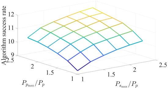
Figure 6.
Impact of and on the algorithm success rate.
The success rate of the covert algorithm versus the number of secondary units in the system (N) is investigated in Figure 7, where , , , and are used. The results of this figure emphasize that the performance of the algorithm improves with increasing the number of secondary units. As the system includes more secondary devices, the probability of finding an SU with channels gains that meet the requirements in (16) increases as well. The algorithm success rate increases rapidly versus the number of devices (till about 20–30); after that, increasing N leads to marginal improvement in the algorithm success rate.
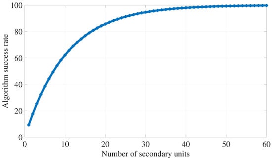
Figure 7.
Impact of N on the algorithm success rate.
A Monte Carlo simulation of a typical communication environment is conducted for the following numerical results. For this simulation, , , , , and are used. In the simulation environment, the channel strengths are randomly generated and they follow a slow-fading Rayleigh distribution, and each fading interval follows an exponential distribution with a mean of 100 bits. Further, each bit is sampled 10 times by the adversary to determine if it corresponds to an idle or active PU. SNR values of 5–20 dBs are tested with 1 million samples each; in each sample, random binary values of and are generated. From the perspective of the covert transmission strategy, the case of PU being always active is considered in the simulation as a worst-case scenario.
The simulation measures the performance of AU in this environment. Specifically, the ability of the adversary to correctly identify the transmission state of PU is quantified through calculating the traffic detection accuracy percentage by dividing the number of correctly identified cases (i.e., when AU determines that PU is being active) by the total number of trials. In addition, the bit error rate of the adversary is used as measure of the quality of the received signal at AU. For both of these measures, lower values of detection accuracy indicate the increased inability of the adversary to distinguish primary traffic from noise. Similarly, higher values of bit error rate mean the received signal at AU is unreliable for signal detection. The success of the proposed covert transmission strategy can be inferred when the adversary’s bit error rate is high and when its traffic detection accuracy is low.
The results of the simulation are shown in Figure 8 for the case when the proposed algorithm is not activated (i.e., a base case to compare the algorithm with), in Figure 9 for the case when (i.e., the worst-case scenario from the perspective of the adversary, and is used as a baseline for the algorithm), and in Figure 10 for the random case. When the algorithm is activated, it is observed that AU’s ability to detect the primary traffic diminishes for reasonable SNR values, reaching around and for SNR values of 10 and 20 dBs, respectively. These low detection accuracy results show that AU is unable (most of the time) of detecting the true nature of the signal and confuses PU’s transmission with noise.
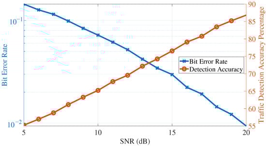
Figure 8.
Adversary’s detection accuracy and bit error rate (assuming covert transmission strategy is not activated).
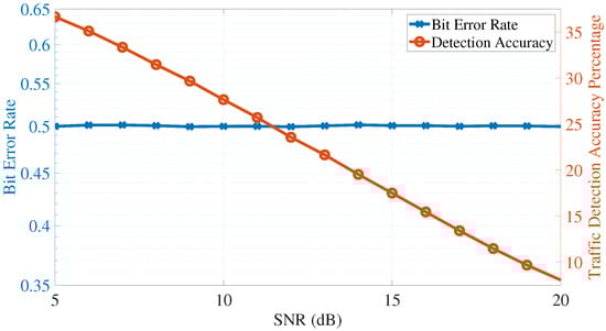
Figure 9.
Adversary’s detection accuracy and bit error rate (covert transmission strategy is activated and assuming ).
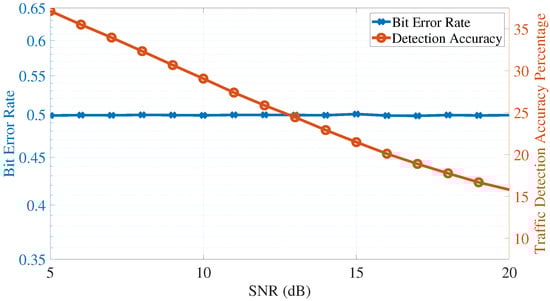
Figure 10.
Adversary’s detection accuracy and bit error rate (covert transmission strategy is activated and assuming is random and is independent of ).
In addition, the bit error rate at AU is around for all tested SNR values when the covert transmission strategy is active; this indicates a worst-case scenario for the adversary where half of the bits are detected in error, suggesting that the received signal at AU is unusable. The results of this simulation emphasize the success of the proposed covert transmission strategy in confusing the adversary about the state of transmission of the primary unit and making the received signal unusable for bit detection.
Further, Figure 11 measures the average precoding power for PU (i.e., ) and that of SU (i.e., ) and their sum as a function of the SNR value. This metric measures the cost of applying the proposed transmission strategy to achieve the required covertness. Recall that the transmitted power of PU is , which is, as shown in the figure, ≈0.3; similarly, the transmitted power of SU is . The results in this figure emphasize that while achieving a measure of covertness, the transmission strategy does not lead to increased transmission power for both the primary and secondary units in the system.
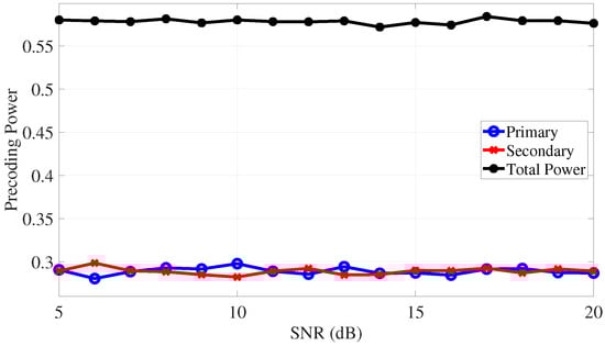
Figure 11.
Precoding power.
We next discuss the impact of nonideal measurements on the performance of the covert algorithm. This includes errors in measurements of channel strength, quantization of these values, measurement delays, and adaptive adversaries. Channel estimation errors refer to the difference between the actual strength of the wireless communication channel and the estimated values used by the devices for the algorithm calculations; this error arises because the estimation process relies on limited or imperfect information about the channel, such as training sequences or feedback, and is influenced by noise and other impairments. Figure 12 shows that the proposed algorithm is robust to channel estimation errors, and that the performance is not severely impacted by channel estimation errors in the range of the figure.
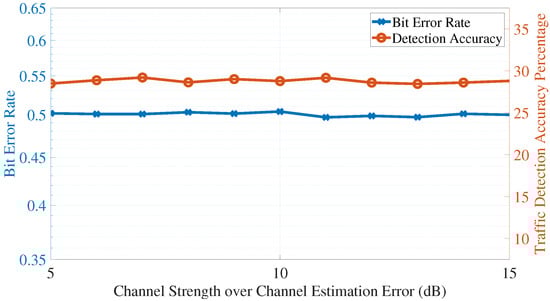
Figure 12.
Impact of channel estimation errors.
Channel quantization errors refer to the errors introduced when analog channel measurements are converted for processing to digital values with a limited number of levels. Figure 13 studies the impact of having limited number of quantization levels on the performance of the algorithm (measured in detection accuracy and bit error rate of the adversary unit). The results of this figure also confirm the robustness of the proposed algorithm to channel uncertainties.
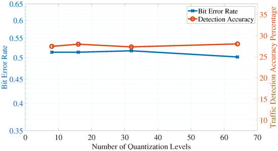
Figure 13.
Impact of quantization errors.
7. Discussion
The numerical results in Section 6 align with the analytical development in Section 4. For example, the scatter and histogram plots emphasize the constraints on the primary and secondary channel strengths; it appears from the numerical also results that the covert transmission strategy favors cooperative units with strong channels with the intended receiver and weaker channels with the adversary unit. Also, it is observed that relaxing the mismatch bounds leads to better chances of finding suitable secondary units; further, the maximum allowed transmission powers are found to have less impact on the algorithm’s success rate.
In addition, having more secondary units in the system enhances the chances of finding ones that meet the transmission constraints, which leads to better chances of confusing the adversary about the state of transmission of the targeted IoT device. Finally, the Monte Carlo simulation shows the efficacy of the proposed covert algorithm in confusing the adversary about the transmission state of the targeted device, making the adversary’s traffic detection attack unsuccessful.
Recent work includes [36], where it investigates a covert communication scheme using half-duplex amplify-and-forward multi-antenna relay configuration, cooperative jammers are used in [37] to obscure downlink messages, reconfigurable intelligent surfaces are used in [38,39] for covert communication, and [40] investigates employing cooperative radar to improve the covert transmission by jamming adversary targets. In comparison with this recently published academic literature, the covert transmission strategy proposed in this article is novel and timely.
The works in [22,26,28] represent recent publications related to covert communications. With the assistance of friendly nodes, a reliable rate of transmission between Alice and Bob without detection by an adversary Willie is deduced in [26]; in this situation, the friendly nodes closest to the adversary produce artificial noise to jam the adversary. A cooperative deception strategy is developed in [28] to diminish the reception ability of a multi-antenna adversary, maximize the covert rate, and optimize the total transmission power; in this environment, the friendly node injects artificial noise to degrade the adversary’s ability to detect the transmission of the intended node. In addition, wireless shadow networks that include transmitters, receivers, and friendly artificial noise-generating nodes are considered in [22] with the objective to impair the detection ability of the adversary.
One difference between our work and the works in [22,26,28] is that we propose an algorithmic approach in contrast to rate limits. Also, our algorithm handles the case when the primary unit is idle, and the covert strategy ensures that covert communication holds to limit the efficacy of the traffic detection attacks. Further, we measure the efficacy of the covert scheme through measuring the adversary’s ability to detect the traffic and through its bit error rate. Further, rather than generating artificial noise, the friendly nodes in our proposal aid in the covert process through transmitting their own precoded data signals.
Considering the performance of the covert transmission strategy against nonideal channel conditions and measurements, the algorithm appears robust to measurement errors and quantization effects of channel strength values. Further, with slow block-fading channels used in modeling the communication environment, the impact measurement delays is expected to be insignificant on the algorithm as the channel characteristics slowly change over time, leading to lower deviation between actual channel strength and measured values. The impact of adaptive adversaries can manifest in changing values of the detection threshold () as described in (3); the covert algorithm reacts to adaptive adversaries through periodically updating the value of in Algorithm 1. This way, the covert transmission strategy stays up-to-date with changing environment variables and adaptive adversaries.
8. Conclusions
This article presents a framework to mitigate traffic detection attacks using a cooperative communication scheme. A covert transmission strategy is proposed to help an IoT device increase the likelihood of an adversary making incorrect conclusions about its transmission state, and the covert strategy addresses both active and idle states of the targeted IoT device and allows other devices to cooperate while not wasting transmission power. Inspired by zero-forcing precoding concepts, an algorithmic covert strategy is developed that favors cooperative devices that meet specific channel strength requirements with the adversary and the intended receiver. In addition, the covert transmission strategy can adjust its algorithm to mitigate adaptive adversaries; for example, the threshold can be updated to reflect changing communication environments or attack behaviors and/or objectives.
The numerical results demonstrate the usefulness of the developed algorithm in facilitating cooperation between the IoT devices, mitigating the traffic detection attacks, and enhancing the information confidentiality of the targeted devices. A future extension of this work includes experimental validation of the proposed covert communication strategy in a real-life IoT environment.
Funding
This research received no external funding.
Institutional Review Board Statement
Not applicable.
Informed Consent Statement
Not applicable.
Data Availability Statement
The raw data supporting the conclusions of this article will be made available by the authors on request.
Conflicts of Interest
The author declares no conflicts of interest.
References
- Larrivaud, L. State of Enterprise IoT Security in North America: Unmanaged and Unsecured; A Forrester Consulting Thought Leadership Paper Commissioned by Armis Inc.; Armis Inc.: San Francisco, CA, USA, 2019. [Google Scholar]
- binti Mohamad Noor, M.; Hassan, W.H. Current research on Internet of Things (IoT) security: A survey. Comput. Netw. 2019, 148, 283–294. [Google Scholar] [CrossRef]
- Kausar, F.; Aljumah, S.; Alzaydi, S.; Alroba, R. Traffic analysis attack for identifying users’ online activities. IT Prof. 2019, 21, 50–57. [Google Scholar] [CrossRef]
- Di Ying, B.; Makrakis, D.; Mouftah, H. Anti-traffic analysis attack for location privacy in WSNs. EURASIP J. Wirel. Commun. Netw. 2014, 2014, 131. [Google Scholar] [CrossRef]
- Trujillo, A.G.S.; Orozco, A.L.S.; Villalba, L.J.G.; Kim, T.H. A traffic analysis attack to compute social network measures. Multimed. Tools Appl. 2019, 78, 29731–29745. [Google Scholar] [CrossRef]
- Feghhi, S.; Leith, D. A web traffic analysis attack using only timing information. IEEE Trans. Inf. Forensics Secur. 2016, 11, 1747–1759. [Google Scholar] [CrossRef]
- Farraj, A.; Hammad, E. A Physical-Layer Security Cooperative Framework for Mitigating Interference and Eavesdropping Attacks in Internet of Things Environments. Sensors 2024, 24, 5171. [Google Scholar] [CrossRef] [PubMed]
- Farraj, A.; Hammad, E. Noise-Based Active Defense Strategy for Mitigating Eavesdropping Threats in Internet of Things Environments. Computers 2025, 14, 6. [Google Scholar] [CrossRef]
- Goel, S.; Negi, R. Guaranteeing secrecy using artificial noise. IEEE Trans. Wirel. Commun. 2008, 7, 2180–2189. [Google Scholar] [CrossRef]
- Son, H. Performance Analysis of Artificial-Noise-Based Secure Transmission in Wiretap Channel. Mathematics 2024, 13, 32. [Google Scholar] [CrossRef]
- Yildirim, H.C.; Keskin, M.F.; Wymeersch, H.; Horlin, F. Deceptive Jamming in WLAN Sensing. In Proceedings of the IEEE Radar Conference (RadarConf24), Denver, CO, USA, 6–10 May 2024; pp. 1–6. [Google Scholar]
- Li, B.; Fei, Z.; Zhou, C.; Zhang, Y. Physical-layer security in space information networks: A survey. IEEE Internet Things J. 2019, 7, 33–52. [Google Scholar] [CrossRef]
- Soni, A.; Upadhyay, R.; Jain, A. Internet of Things and wireless physical layer security: A survey. In Proceedings of the Computer Communication, Networking and Internet Security, Dallas, TX, USA, 30 October–3 November 2017; pp. 115–123. [Google Scholar]
- Rojas, P.; Alahmadi, S.; Bayoumi, M. Physical layer security for IoT communications—A survey. In Proceedings of the 7th World Forum on Internet of Things (WF-IoT), New Orleans, LA, USA, 14 June–31 July 2021; pp. 95–100. [Google Scholar]
- Mukherjee, A. Physical-Layer Security in the Internet of Things: Sensing and Communication Confidentiality Under Resource Constraints. Proc. IEEE 2015, 103, 1747–1761. [Google Scholar] [CrossRef]
- Kim, M.S.; Kong, H.J.; Hong, S.C.; Chung, S.H.; Hong, J.W. A flow-based method for abnormal network traffic detection. In Proceedings of the IEEE/IFIP Network Operations and Management Symposium, Seoul, Republic of Korea, 23 April 2004; Volume 1, pp. 599–612. [Google Scholar]
- Niakanlahiji, A.; Orlowski, S.; Vahid, A.; Jafarian, J.H. Toward practical defense against traffic analysis attacks on encrypted DNS traffic. Comput. Secur. 2023, 124, 103001. [Google Scholar] [CrossRef]
- Purwanto, Y.; Kuspriyanto; Hendrawan; Rahardjo, B. Traffic anomaly detection in DDos flooding attack. In Proceedings of the 8th International Conference on Telecommunication Systems Services and Applications (TSSA), Kuta, Indonesia, 23–24 October 2014; pp. 1–6. [Google Scholar]
- Chen, X.; An, J.; Xiong, Z.; Xing, C.; Zhao, N.; Yu, F.R.; Nallanathan, A. Covert communications: A comprehensive survey. IEEE Commun. Surv. Tutor. 2023, 25, 1173–1198. [Google Scholar] [CrossRef]
- Li, Z.; Shi, J.; Si, J.; Lv, L.; Guan, L.; Hao, B.; Tie, Z.; Wang, D.; Xing, C.; Quek, T.Q. Intelligent Covert Communication: Recent Advances and Future Research Trends. Engineering 2025, 44, 101–111. [Google Scholar] [CrossRef]
- Jiang, Y.; Wang, L.; Chen, H.H.; Shen, X. Physical layer covert communication in B5G wireless networks—Its research, applications, and challenges. Proc. IEEE 2024, 112, 47–82. [Google Scholar] [CrossRef]
- Bash, B.A.; Goeckel, D.; Towsley, D.; Guha, S. Hiding information in noise: Fundamental limits of covert wireless communication. IEEE Commun. Mag. 2015, 53, 26–31. [Google Scholar] [CrossRef]
- Liu, Z.; Liu, J.; Zeng, Y.; Ma, J. Covert Wireless Communications in IoT Systems: Hiding Information in Interference. IEEE Wirel. Commun. 2018, 25, 46–52. [Google Scholar] [CrossRef]
- He, B.; Yan, S.; Zhou, X.; Jafarkhani, H. Covert wireless communication with a Poisson field of interferers. IEEE Trans. Wirel. Commun. 2018, 17, 6005–6017. [Google Scholar] [CrossRef]
- Shahzad, K.; Zhou, X.; Yan, S.; Hu, J.; Shu, F.; Li, J. Achieving covert wireless communications using a full-duplex receiver. IEEE Trans. Wirel. Commun. 2018, 17, 8517–8530. [Google Scholar] [CrossRef]
- Soltani, R.; Goeckel, D.; Towsley, D.; Bash, B.A.; Guha, S. Covert wireless communication with artificial noise generation. IEEE Trans. Wirel. Commun. 2018, 17, 7252–7267. [Google Scholar] [CrossRef]
- Lv, L.; Li, Z.; Ding, H.; Al-Dhahir, N.; Chen, J. Achieving covert wireless communication with a multi-antenna relay. IEEE Trans. Inf. Forensics Secur. 2022, 17, 760–773. [Google Scholar] [CrossRef]
- Si, J.; Liu, Z.; Li, Z.; Hu, H.; Guan, L.; Wang, C.; Al-Dhahir, N. A Cooperative Deception Strategy for Covert Communication in Presence of a Multi-Antenna Adversary. IEEE Trans. Commun. 2023, 71, 4778–4792. [Google Scholar] [CrossRef]
- Wu, H.; Zhang, Y.; Shen, Y.; Jiang, X.; Taleb, T. Achieving covertness and secrecy: The interplay between detection and eavesdropping attacks. IEEE Internet Things J. 2024, 11, 3233–3249. [Google Scholar] [CrossRef]
- An, J.; Kang, B.; Ouyang, Q.; Pan, J.; Ye, N. Covert communications meet 6G NTN: A comprehensive enabler for safety-critical IoT. IEEE Netw. 2024, 38, 17–24. [Google Scholar] [CrossRef]
- Farraj, A. Coordinated Security Measures for Industrial IoT Against Eavesdropping. In Proceedings of the IEEE Texas Power and Energy Conference (TPEC), College Station, TX, USA, 13–14 February 2023; pp. 1–5. [Google Scholar]
- Farraj, A. Cooperative Transmission Strategy for Industrial IoT Against Interference Attacks. In Proceedings of the IEEE Texas Power and Energy Conference (TPEC), College Station, TX, USA, 13–14 February 2023; pp. 1–6. [Google Scholar]
- Ryu, D.; Lee, S.; Yang, S.; Jeong, J.; Lee, Y.; Shin, D. Enhancing Cybersecurity in Energy IT Infrastructure Through a Layered Defense Approach to Major Malware Threats. Appl. Sci. 2024, 14, 10342. [Google Scholar] [CrossRef]
- Poor, H.V.; Schaefer, R.F. Wireless physical layer security. Proc. Natl. Acad. Sci. USA 2017, 114, 19–26. [Google Scholar] [CrossRef]
- Wiesel, A.; Eldar, Y.C.; Shamai, S. Zero-forcing precoding and generalized inverses. IEEE Trans. Signal Process. 2008, 56, 4409–4418. [Google Scholar] [CrossRef]
- Jin, Q.; Fan, L.; Lei, X.; Zhao, J.; Nallanathan, A. Covert communication of multi-antenna af relaying networks. IEEE Trans. Commun. 2025, 73, 5699–5714. [Google Scholar] [CrossRef]
- Wen, Y.; Liu, L.; Li, J.; Li, Y.; Wang, K.; Yu, S.; Guizani, M. Covert communications aided by cooperative jamming in overlay cognitive radio networks. IEEE Trans. Mob. Comput. 2024, 23, 12878–12891. [Google Scholar] [CrossRef]
- Zhang, Y.; Yang, L.; Li, X.; Guo, K.; Liu, H. Covert communications for STAR-RIS-assisted industrial networks with a full duplex receiver and RSMA. IEEE Internet Things J. 2024, 11, 22483–22493. [Google Scholar] [CrossRef]
- Li, X.; Liu, M.; Dang, S.; Luong, N.C.; Yuen, C.; Nallanathan, A.; Niyato, D. Covert Communications with Enhanced Physical Layer Security in RIS-Assisted Cooperative Networks. IEEE Trans. Wirel. Commun. 2025, 24, 5605–5619. [Google Scholar] [CrossRef]
- Wang, X.; Fei, Z.; Liu, P.; Zhang, J.A.; Wu, Q.; Wu, N. Sensing aided covert communications: Turning interference into allies. IEEE Trans. Wirel. Commun. 2024, 23, 10726–10739. [Google Scholar] [CrossRef]
Disclaimer/Publisher’s Note: The statements, opinions and data contained in all publications are solely those of the individual author(s) and contributor(s) and not of MDPI and/or the editor(s). MDPI and/or the editor(s) disclaim responsibility for any injury to people or property resulting from any ideas, methods, instructions or products referred to in the content. |
© 2025 by the author. Licensee MDPI, Basel, Switzerland. This article is an open access article distributed under the terms and conditions of the Creative Commons Attribution (CC BY) license (https://creativecommons.org/licenses/by/4.0/).