Article

Reem-Shape Phononic Crystal for Q Anchor Enhancement of Thin-Film-Piezoelectric-on-Si MEMS Resonator

School of Integrated Circuits Science and Engineering, University of Electronic Science and Technology of China, Chengdu 611731, China
*
Authors to whom correspondence should be addressed.
Micromachines 2023, 14(8), 1540; https://doi.org/10.3390/mi14081540
Submission received: 24 June 2023 / Revised: 17 July 2023 / Accepted: 29 July 2023 / Published: 31 July 2023
(This article belongs to the Special Issue Acoustic Transducers and Their Applications)

Abstract

:
This paper proposes a reem-shaped phononic crystal for the performance enhancement of TPoS resonators. The proposed phononic crystal offers an ultra-wide acoustic band gap that prevents energy leakage through the supporting substrate upon its placement at the anchoring boundary, resulting in significant improvements in the resonator quality factor. Simulated results show reem-shape phononic crystals generate a band gap up to 175 MHz with a BG of 90% and enhance the anchor quality factor from 180,000 to 6,000,000 and the unloaded quality factor from 133,000 to 160,000, representing 33.3-fold and 1.2-fold improvements, respectively.

1. Introduction

Micromachined resonators have a great possibility for integration with microelectronics at the die or package level [1,2,3,4,5]. This advantage leads to reduced cost, a smaller form factor, enhanced performance, and decreased fabrication complexity. Micromachined resonators are grouped into three main categories: piezoelectric resonators, capacitive resonators, and piezoresistive resonators. Piezoelectric micromachined resonators have proven excellent performance and strong reliability in timing applications and also have good merits such as a strong electromechanical coupling coefficient [6], a large Q, better temperature stability, and the possibility of the resonator being implemented and fabricated on a silicon substrate at the die level [7].
Micromachined resonators with large Q are commonly used in oscillators with low phase noise and filters with low insertion loss [8]. However, before MEMS resonators spread commercially in markets over other types of resonant devices, some loss factors should be mitigated. These losses are thermo-elastic damping (TED), support (anchor loss) [9,10], material loss [11], and other losses like resistive loss, surface loss, and dielectric loss [12,13]. In this regard, the quality factor of the micromachined resonator consists of many branches, such as anchor quality factor (Qanchor), electrode quality factor (Qelectrode), TED quality factor (QTED), material quality factor (Qmaterial), and unknown quality factor (Qunknown). The equivalent Q can be expressed with the following equation [14]:
Q = 2 π   E s t o r e d E l o s s
where Estored and Eloss represent the stored and dissipated energy in the resonator, respectively. Anchor loss represents the major loss of the piezoelectric resonators vibrating in width extension mode. This loss is due to the radiation of acoustic waves to the supporting substrate through tethers. One of the mechanisms used to mitigate this loss is using acoustic reflectors [15,16]. The shortcoming of this method is its inefficiency in reducing anchor loss. The other recently introduced method of improving the Q of the resonator is using energy-preserving suspended frames [17]. Even though it is reported to provide a significant improvement in Q, it introduces spurious modes near the intended resonance mode. The most widely used method is to apply one- or two-dimensional phononic crystals on anchors of the resonator or on supporting tethers, which is provided by many researchers [18,19,20]. Different types of effective phononic crystals have been achieved. This article introduces a new 2-D phononic crystal structure (Reem-PnC) that generates a wide acoustic band gap up to 175 MHz, resulting in a high anchor quality factor of 6,000,000.

2. Phononic Crystal & Theory of Wave Propagation

2.1. Principle of Wave Propagation in PnCs

The periodic structure of phononic crystals consists of two or more elastic materials with excellent mechanical properties [21,22,23]. Properly designed phononic crystals provide some range of frequencies in which acoustic waves are inhibited from propagating. This range of frequencies is defined as an “acoustic band gap” [24]. Bloch’s theorem is usually used to characterize the propagation of waves in acoustic mediums (phononic crystals) and periodic dielectric mediums (photonic crystals) [25]. The equation of the acoustic wave propagation in material with anisotropic nature can be written as [26,27,28]:
x j C i j k l u k x l = ρ ϋ i
where xj represents the coordinate axes (x, y, z), Cijkl represents the tensor of elastic material, ui represents the components of displacement (ux, uy, uz), and ρ is the silicon density. To calculate the bandgap, the two boundary destinations on the unit cell (a) are adjusted to Bloch’s periodic boundary conditions through all the propagation directions. The Bloch-Floquet theorem verifies the periodic boundary condition of displacements as defined by [23]:
ui (x,y,z + a,t) = ui (x,y,z,t) ejka
where k and a represent the wave number and the lattice constants of the PnC. All frequency eigenmodes can be calculated by sweeping k through the boundaries of the first irreducible Brillouin zone (IBZ) in the single structure of the phononic crystal. The frequencies are a function of k (k = ω/c), where c represents acoustic wave velocity along the (110) direction of silicon and ω represents angular frequency. The relation among generated displacement due to stress can be expressed as [23]:
ui(x + a,t) = ejk.a ui(x, t)
σij(x, + a,t) = ejk.a σij(x, t)
The Bloch profile shows the calculations of changes in displacements, eigenfrequencies, and stress fields as k varies gradually. Many curves are achieved between k and ω due to varying wave vectors through all highly symmetric edges of the first IBZ of the Reem-PnC. All the calculations of equations and solutions are done using COMSOL Multiphysics through the FE analysis method.

2.2. PnC Design

The Reem-PnC is illustrated in Figure 1a,b. The structure of a single unit cell with lattice constant a = 16 μm consists of two cross blocks perpendicular to each other with widths and lengths of 12 μm, 8 μm, and 8 μm, 12 μm, respectively, a high of h = 10 μm, and chamfered edges of radius R = 1 μm. This PnC is connected to arrays of PnCs by four connectors with widths and lengths of 2 μm and 1 μm. All the designs were constructed using single-crystal silicon, the mass density of silicon ρ = 2330 kg/m3, and the elastic constants illustrated in Table 1.
The axes (x, y, and z) of the lattice synchronized with the (110), (110), and (001) directions of the original orientation of the silicon wafer (i.e., 100). Adding Floquet periodic boundary conditions at the edges of the unit cell and sweeping the parameters of k through the direction of Γ-X-M-Γ for the first IBZ, as illustrated in Figure 1a. The first eigenfrequency modes of Reem-Shape PnC with the associated bandgap are illustrated in Figure 2a,b. The desired design of PnC achieves a complete bandgap of 175 MHz in the frequency range between 105–280 MHz with a (w) of 1 μm and 135 MHz in the frequency range between 125–275 MHz with a (w) of 2 μm.
Reem phononic crystal generates a wide bandgap from 105 MHz to 280 MHz. The ratio between gap and mid-gap is determined by the equation [24]:
B a n d g a p = f t o p f b o t f t o p + f b o t 2
where fbot and ftop represent the open and closed frequencies of the bandgap. A wide acoustic bandgap is obtained with a BG of 90% from Reem-PnC dimensions as mentioned above with a connector of w = 1 μm; changing the connector width to 2 μm achieves a decrease in bandgap BG of 75% as shown in Figure 2c. The comparison of Reem-PnC with other PnC shapes is illustrated in Table 2. The filling fraction of the Reem-PnC, which represents the area of PnC relative to the area of the lattice, is equal to 0.515, and it is calculated using the equation [24]:
f i l l i n g   f r a c t i o n = a r e a   o f   P n C a r e a   o f   l a t t i c e

3. Transmission Characteristics of Reem-PnC
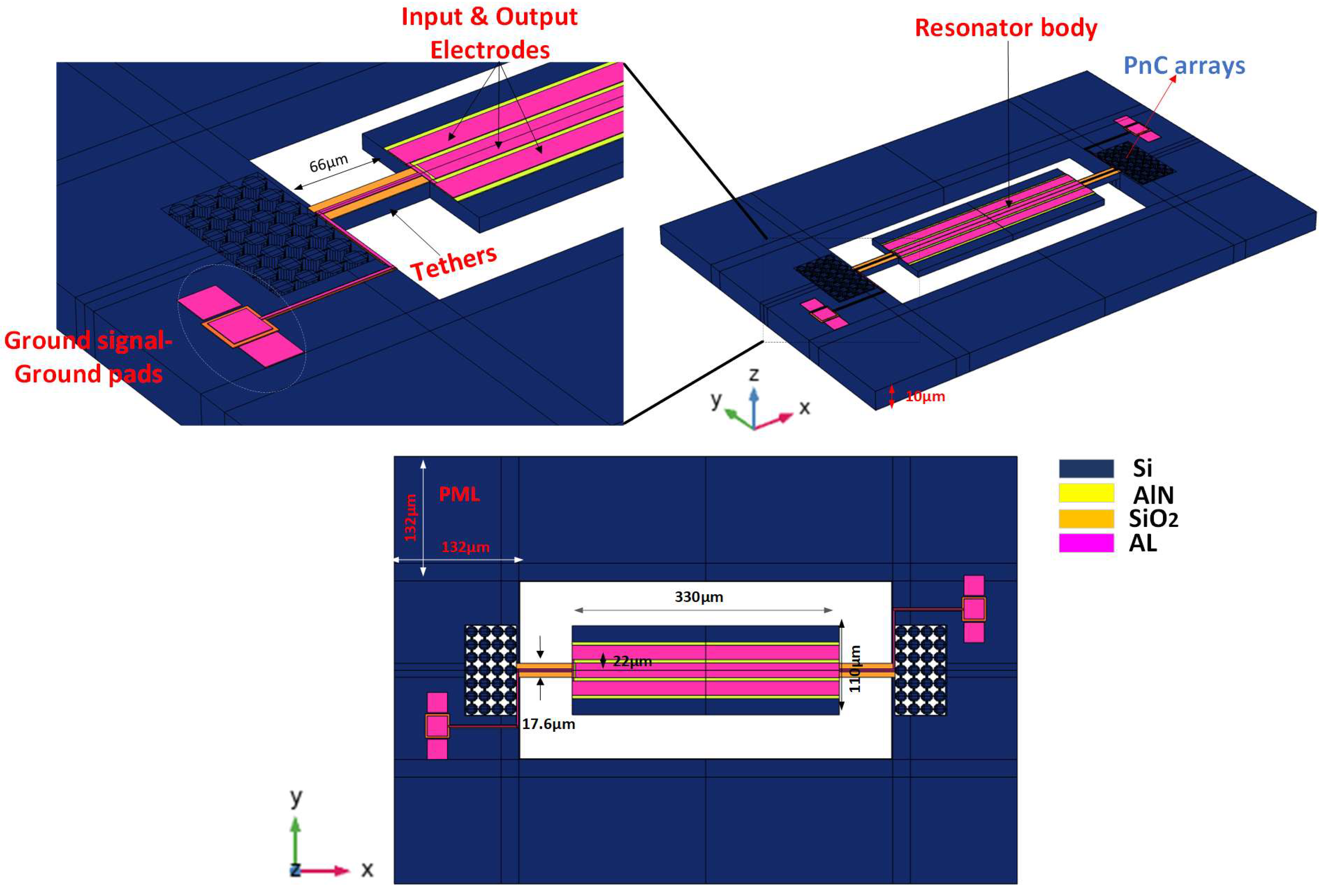
To prove the formation of the acoustic bandgap by the Reem-PnC structure, the transmission characteristic is analyzed using two acoustic delay lines. As shown in Figure 3b, the Reem PnC plate and silicon plate (two different transmission mediums among sense and drive electrodes) are applied to realize the transmission characteristics of the desired PnC. The end of each delay line boundary in the x-direction is perfectly matched to effectively decrease the reflected wave interface. The drive electrode is excited by 0.01 watts, and the sense electrodes are terminated at 0.0 watts. The transmission (S21) is calculated using the following relationship [29]:
S 21 d B = 10   l o g 10   P o u t P i n
where Pin and Pout are the input and output power transferred to the Reem-PnC delay line and solid silicon delay line, respectively, as shown in Figure 3b. S21 represents the transmission power coefficient between the input and output ports. Clearly from Figure 3b, the S21 transmission spectrum with an array of Reem-PnC proofs the proposed design successfully forms an acoustic bandgap. The finite element simulation results (displacement profile) illustrate that the wave is strongly attenuated in the transmission spectra at the beginning of the Reem-PnC delay line and continues to zero, compared to the silicon plate delay line. Reem-PnC satisfies that there is a strong prohibition on the propagation of acoustic waves.

4. Resonator Design

The resonator design can be realized as a mass-spring-damper system. All vibrating systems have energy dissipation mechanisms. This mechanism is characterized simply as a damper. The union of the mass-spring-damper system is the basic model for the resonator. Clearly, from Figure 4b, Newton’s second law of motion realizes the relations between the motion of mass and input force, which are generally expressed by [1]:
m e q 2 x t 2 + c e q x t + k e q x = F                                              
where meq represents equivalent mass, F represents applied force, keq represents equivalent stiffness, and ceq is the equivalent total loss. The relationship between the input and output of the system can be expressed as [1]:
                                H s = X s F s = 1 m e q 2 + c e q s + k e q = 1 k e q ω n 2 s 2 + ω n Q 1 S + ω n 2
where (s) is defined as complex frequency, Q is defined as body quality factor, and ω n defined as the natural frequency. The resonant frequency for systems of second order is given by [24]:
ω n = 2 π f n = k e q m e q                                                                            
The relation between natural frequency ωn and the resonance frequency ωr of the system of second order is expressed by [1]:
          ω r = ω n 1 1 2 Q 2
It is clear from the above relation that for high Q, as in MEMS resonators, the natural frequency equals the resonance frequency (i.e., ωrωn). By applying a single frequency analysis, the resonance frequency of the MEMS resonator can be extracted from the displacement curve in the frequency response by using the general formula [20]:
Q = f r Δ f 3 d B
where Δf(−3dB) is defined as the −3 dB bandwidth between the resonant frequency and the frequency response curve. In all cases, the resonator is expressed as an electric circuit with series R, L, and C. Figure 4b,c show an equivalent mechanical and electrical model for a MEMS resonator. The input voltage represents the input force, the current represents velocity, the damping loss is represented by Rm (motional resistance), the Cm (motional capacitance) is represented by the inverse of stiffness, and the mass is represented by the motional inductance Lm. The relation among Rm, Cm, Qu (unloaded quality factor), and insertion loss IL of the resonator is given by [3]:
R m = 1 R e l Y 11 ,         R m = 1 2 π f r C m Q u
where Y11 is the admittance curve of the resonator.
A 5th-order piezoelectric on silicon MEMS resonator was implemented, simulated, and analyzed using COMSOL Multiphysics, as demonstrated in Figure 5. A thin film of the AlN layer is bonded to a silicon substrate. The Al electrode positioned on top of piezoelectric material with a depth of 0.5 μm excites the vibration on the piezoelectric resonator by applying a voltage of 1 V, while the gap between the two electrodes is set to be 0.4 μm. The dimensions of the resonator are 110 μm width and 330 μm length, respectively. The wavelength of the resonator λ is equal to 44 μm. The tether length and width of the desired resonator are set to 1.5 λ and 17.6, respectively. A Reem-PnC consists of two cross blocks perpendicular to each other with width and length of 12 μm and 8 μm, respectively, chamfering radius R at the edges of 1 μm, and lattice constant a = 16 μm. The PnC arrays are positioned externally in anchors to generate a bandgap that coincides with the resonant frequency to prohibit acoustic wave propagation to the device substrate and cause a loss in energy. The resonant frequency (fr) of the resonator body can be obtained from [16]:
f r = 1 λ E ρ
where λ defined as wavelength, E is defined as Young’s modulus in (110) axes, and ρ defined as the density of single-crystal silicon. The fr calculated from Equation (16) is around 191 MHz in the desired design λ = 44 μm. The resonator design parameters are listed in Table 3.

5. Techniques for Anchor Loss Enhancement in the Resonator

A 2-dimensional array of Reem-PnC is deployed in the anchoring boundaries of the resonator to enhance the anchor quality factor and, as a result, the total quality factor (Qtot). From Figure 6, the Qanchor of the TPoS MEMS resonator can be generally obtained from the resonance frequency divided by the −3 dB of bandwidth of the resonance maximum point in displacement profile at the frequency response [16]:
Q a n c h o r = f r Δ f 3 d B
where fr is defined as resonance frequency, the resonator mode shape with and without PnC and associated anchor quality factor are shown in Figure 6.

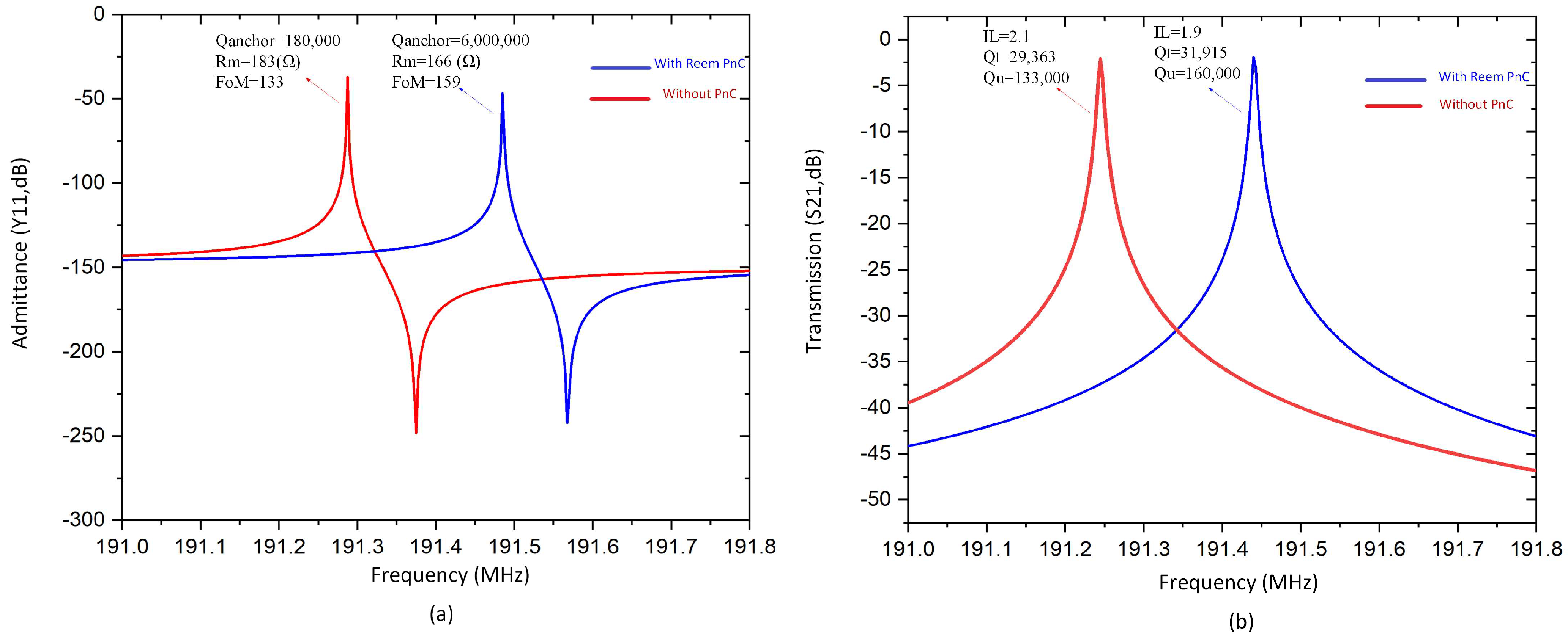
6. Calculation of Resonator Performance

Simulated S21 parameters and admittance Y11 curves of a desired resonator with and without Reem-PnC were calculated by the FEA simulation at the frequency domain in COMSOL Multiphysics to obtain the insertion loss, loaded Q, unloaded Q, the figure of merit, effective electromechanical coupling coefficient (k2eff), and motional resistance Rm. The relationships of Q, Qu, FoM, and k2eff are given by [30]:
Q l = f r Δ f 3 d B ,   Q u = Q l 1 10 I L 20 ,   k e f f 2 = π 2 8 f s 2 f p 2   f p 2 ,   F o M = Q u k e f f 2

7. Discussion

Figure 7 presents different values of the anchor quality factor as a function of longitudinal wavelength (λ. The minimum value of the anchor quality factor exists at the tether length equal to integer multiples of the wavelength (i.e., 1*λ, 2*λ, 3*λ), while the maximum points of Q are obtained at the integer multiples of a quarter of the wavelength. The maximum Qanchor was achieved at 1.5 λ.
Figure 8 illustrates the displacement plot across the line A-A′, which verifies the proposed resonator with Reem-PnC and offers a high enhancement in the total displacement of the resonator in comparison with the resonator without PnC. This verifies that the amount of stored energy in the resonator with Reem-PnC is larger than the resonator without PnC.
Figure 9a,b illustrates the absolute value of the z component displacement field along the B–B′ line in the two resonators with and without Reem-PnC. It is clear from the plot that the displacement at peak point P1 in the tether is higher than the displacement at peak point P2. Continuously, the displacement in the resonator is enhanced in comparison between points P′1 and P′2. Figure 9c,d illustrate the absolute value of the x component displacement field along the B–B′ line. It is clear from the plots that the displacement of the peak point P3 in the tethers is greater than the displacement in point P4, and the displacement component in the resonator is enhanced in comparison between points P′3 and P′4. The displacement components x and z in the resonator with Reem-PnC are greater than those in the resonator without PnC.
It is clearly shown from Figure 10 that there is no significant displacement in the PnC array at the anchor boundary of the resonator with Reem-PnC as in cutting plane C-C′. Also, the displacement profile in Figure 10a,b shows there is a displacement increase on the anchoring boundaries of the resonator without PnC (i.e., Δdisp = 5.72 μm). This proves there is energy loss due to energy transverse from the resonant body to the anchor’s boundary.
As is seen from Table 4, the simulated Qanchor and Qu of the designed resonator with Reem-shape PnC are enhanced by 13.5 and 1.2 folds, respectively, in comparison with the resonator without PnC. The remaining parameters of the resonator, such as insertion loss (IL) and motional resistance (Rm), were obtained from the transmission magnitudes (S21, dB) and admittance (Y11, dB) at the quarter of the resonator, as shown in Figure 11. The plots of the parameters are illustrated in Figure 12a,b, respectively. These parameters clearly show enhancement due to the proposed design, while keff remains unchanged.

8. Conclusions

This work proposes Reem-PnC as a new phononic crystal design used for anchor loss reduction in thin-film piezoelectric-on-silicon MEMS resonators. The proposed design generates a wide bandgap that prevents acoustic wave propagation to the support structure. Moreover, tether length and width are tuned to optimum dimensions to achieve a high anchor quality factor. The combination of the two approaches achieves a high-quality factor. In this regard, an anchor quality factor of about 6,000,000 and an unloaded quality factor (Qu) of about 160,000 are obtained from the resonator with Reem-PnC, which accounts for 33.3-fold and 1.2-fold enhancement in comparison with the resonator without PnC, respectively.

Author Contributions

Conceptualization, M.A. and J.-F.B.; formal analysis, M.A.; funding acquisition, M.A., J.-F.B. and K.-y.H.; investigation, M.A. and J.-F.B.; methodology, M.A. and J.-F.B.; project administration, T.B.W., J.-F.B. and K.-y.H.; resources, T.B.W., J.-F.B. and K.-y.H.; software, M.A.; supervision, J.-F.B. and K.-y.H.; validation, J.-F.B. and K.-y.H.; visualization, M.A.; writing—original draft, M.A.; writing—review and editing, J.-F.B. and K.-y.H. All authors have read and agreed to the published version of the manuscript.

Funding

This work is supported in part by the research project under grant A1098531023601318 and in part by the grant from the National Natural Science Foundation of China and the China Academy of Engineering Physics under grant U1430102.

Informed Consent Statement

Informed consent was obtained from all subjects involved in the study.

Conflicts of Interest

The authors declare no conflict of interest.

References

  1. Abdolvand, R.; Bahreyni, B.; Lee, J.E.Y.; Nabki, F. Micromachined resonators: A review. Micromachines 2016, 7, 160. [Google Scholar] [CrossRef] [Green Version]
  2. Bao, F.H.; Wu, X.Q.; Zhou, X.; Wu, Q.D.; Zhang, X.S.; Bao, J.F. Spider web-like phononic crystals for piezoelectric MEMS resonators to reduce acoustic energy dissipation. Micromachines 2019, 10, 626. [Google Scholar] [CrossRef] [Green Version]
  3. Ho, G.K.; Abdolvand, R.; Sivapurapu, A.; Humad, S.; Ayazi, F. Piezoelectric-on-silicon lateral bulk acoustic wave micromechanical resonators. J. Microelectromech. Syst. 2008, 17, 512–520. [Google Scholar] [CrossRef]
  4. Bao, F.H.; Bao, J.F.; Lee, J.E.Y.; Bao, L.L.; Khan, M.A.; Zhou, X.; Wu, Q.D.; Zhang, T.; Zhang, X.S. Quality factor improvement of piezoelectric MEMS resonator by the conjunction of frame structure and phononic crystals. Sens. Actuators A Phys. 2019, 297, 111541. [Google Scholar] [CrossRef]
  5. Bao, F.H.; Awad, M.; Li, X.Y.; Wu, Z.H.; Bao, J.F.; Zhang, X.S.; Bao, L.L. Suspended frame structure with phononic crystals for anchor loss reduction of MEMS resonator. In Proceedings of the 2018 IEEE International Frequency Control Symposium (IFCS), Olympic Valley, CA, USA, 21–24 May 2018; pp. 1–4. [Google Scholar]
  6. Zhu, H.; Lee, J.E.Y. AlN piezoelectric on silicon MEMS resonator with boosted Q using planar patterned phononic crystals on anchors. In Proceedings of the 2015 28th IEEE International Conference on Micro Electro Mechanical Systems (MEMS), Estoril, Portugal, 18–22 January 2015; pp. 797–800. [Google Scholar]
  7. Ha, T.D.; Bao, J. Reducing anchor loss in thin-film aluminum nitride-on-diamond contour mode MEMS resonators with support tethers based on phononic crystal strip and reflector. Microsyst. Technol. 2016, 22, 791–800. [Google Scholar] [CrossRef]
  8. Van Beek, J.T.M.; Puers, R. A review of MEMS oscillators for frequency reference and timing applications. J. Micromech. Microeng. 2011, 22, 013001. [Google Scholar] [CrossRef]
  9. Jimbo, Y.; Itao, K. Energy loss of a cantilever vibrator. J. Horol. Inst. Jpn. 1968, 47, 1–15. [Google Scholar]
  10. Hao, Z.; Erbil, A.; Ayazi, F. An analytical model for support loss in micromachined beam resonators with in-plane flexural vibrations. Sens. Actuators A Phys. 2003, 109, 156–164. [Google Scholar] [CrossRef]
  11. Nowick, A.S.; Berry, B.S. Characterization of Anelastic Behavior. Anelastic Relaxation in Crystalline Solids; Academic Press: New York, NY, USA, 1972. [Google Scholar]
  12. Jonscher, A.K. Dielectric relaxation in solids. J. Phys. D Appl. Phys. 1999, 32, R57. [Google Scholar] [CrossRef]
  13. Seoánez, C.; Guinea, F.; Neto, A.C. Surface dissipation in nanoelectromechanical systems: Unified description with the standard tunneling model and effects of metallic electrodes. Phys. Rev. B 2008, 77, 125107. [Google Scholar] [CrossRef] [Green Version]
  14. Harrington, B.P.; Abdolvand, R. Q-enhancement through minimization of acoustic energy radiation in micromachined lateral-mode resonators. In Proceedings of the TRANSDUCERS 2009—2009 International Solid-State Sensors, Actuators and Microsystems Conference, Denver, CO, USA, 21–25 June 2009; pp. 700–703. [Google Scholar]
  15. Harrington, B.P.; Abdolvand, R. In-plane acoustic reflectors for reducing effective anchor loss in lateral–extensional MEMS resonators. J. Micromech. Microeng. 2011, 21, 085021. [Google Scholar] [CrossRef]
  16. Liu, J.; Workie, T.B.; Wu, Z.; Tang, P.; Bao, J.F.; Hashimoto, K.Y. Acoustic Reflectors for Anchor Loss Reduction of Thin Film Piezoelectric on Substrate Resonators. In Proceedings of the 2021 IEEE MTT-S International Wireless Symposium (IWS), Nanjing, China, 23–26 May 2021; pp. 1–3. [Google Scholar]
  17. Workie, T.B.; Wu, Z.; Tang, P.; Bao, J.; Hashimoto, K.Y. Figure of Merit Enhancement of Laterally Vibrating RF-MEMS Resonators via Energy-Preserving Addendum Frame. Micromachines 2022, 13, 105. [Google Scholar] [CrossRef]
  18. Bao, J.; Workie, T.B.; Hashimoto, K.Y. Performance improvement of RF acoustic wave resonators using phononic crystals. In Proceedings of the 2022 IEEE MTT-S International Microwave Workshop Series on Advanced Materials and Processes for RF and THz Applications (IMWS-AMP), Guangzhou, China, 27–29 November 2022; pp. 1–2. [Google Scholar]
  19. Chen, P.J.; Workie, T.B.; Feng, J.J.; Bao, J.F.; Hashimoto, K.Y. Four-Leaf Clover Shaped Phononic Crystals for Quality Factor Improvement of AlN Contour Mode Resonator. In Proceedings of the 2022 IEEE International Ultrasonics Symposium (IUS), Venice, Italy, 10–13 October 2022; pp. 1–3. [Google Scholar]
  20. Awad, M.; Bao, F.; Bao, J.; Zhang, X. Cross-shaped PnC for anchor loss reduction of thin-film ALN-on-silicon high-frequency MEMS resonator. In Proceedings of the 2018 IEEE MTT-S International Wireless Symposium (IWS), Chengdu, China, 6–10 May 2018; pp. 1–3. [Google Scholar]
  21. Siddiqi, M.W.U.; Lee, J.E.Y. Wide acoustic bandgap solid disk-shaped phononic crystal anchoring boundaries for enhancing quality factor in AlN-on-Si MEMS resonators. Micromachines 2018, 9, 413. [Google Scholar] [CrossRef] [PubMed] [Green Version]
  22. Deymier, P.A. (Ed.) Acoustic Metamaterials and Phononic Crystals; Springer Science & Business Media: Berlin, Germany, 2013; Volume 173. [Google Scholar]
  23. Workie, T.B.; Wu, T.; Bao, J.F.; Hashimoto, K.Y. Design for the high-quality factor of piezoelectric-on-silicon MEMS resonators using resonant plate shape and phononic crystals. Jpn. J. Appl. Phys. 2021, 60, SDDA03. [Google Scholar] [CrossRef]
  24. Tu, C.; Lee, J.Y. Enhancing quality factor by etching holes in piezoelectric-on-silicon lateral mode resonators. Sens. Actuators A Phys. 2017, 259, 144–151. [Google Scholar] [CrossRef]
  25. Zou, J.; Lin, C.M.; Chen, Y.Y.; Pisano, A.P. Theoretical study of thermally stable SiO2/AlN/SiO2 Lamb wave resonators at high temperatures. J. Appl. Phys. 2014, 115, 094510. [Google Scholar] [CrossRef]
  26. Binci, L.; Tu, C.; Zhu, H.; Lee, J.Y. Planar ring-shaped phononic crystal anchoring boundaries for enhancing the quality factor of Lamb mode resonators. Appl. Phys. Lett. 2016, 109, 203501. [Google Scholar] [CrossRef]
  27. Lozzi, A.; De Pastina, A.; Yen, E.T.T.; Villanueva, L.G. Engineered acoustic mismatch for anchor loss control in contour mode resonators. Appl. Phys. Lett. 2019, 114, 103502. [Google Scholar] [CrossRef]
  28. Jiang, S.; Hu, H.; Laude, V. The low-frequency band gap in cross-like holey phononic crystal strip. J. Phys. D Appl. Phys. 2018, 51, 045601. [Google Scholar] [CrossRef] [Green Version]
  29. Khelif, A.; Aoubiza, B.; Mohammadi, S.; Adibi, A.; Laude, V. Complete band gaps in two-dimensional phononic crystal slabs. Phys. Rev. E 2006, 74, 046610. [Google Scholar] [CrossRef] [Green Version]
  30. Pennec, Y.; Vasseur, J.O.; Djafari-Rouhani, B.; Dobrzyński, L.; Deymier, P.A. Two-dimensional phononic crystals: Examples and applications. Surf. Sci. Rep. 2010, 65, 229–291. [Google Scholar] [CrossRef]
Figure 1. (a) 2-D view of Reem-PnC with the first irreducible Brillouin zone (IBZ) (b) 3-D view of Reem-PnC.
Micromachines 14 01540 g001
Figure 2. Illustration of: (a) the first eigenfrequency mode shape in the band structure of Reem-PnC, (b) band structure through (Γ-X-M-Γ) direction of the IBZ of Reem-PnC and (c) transmission of S21 parameters of an array of Reem-PnC unit cells.
Micromachines 14 01540 g002
Figure 3. (a) Displacement distribution of the transmission medium with solid Silicon plate delay line and Reem-PnC array at 191 MHz on the A1–A2 line (b) 3D view of sense and drive electrodes with silicon plate and Reem-PnC.
Micromachines 14 01540 g003
Figure 4. (a) Illustration of piezoelectric excitation in MEMS resonator (b) equivalent mechanical system of the resonator (c) equivalent electrical circuit of the resonator.
Micromachines 14 01540 g004
Figure 5. A 3-D view of the resonator with arrays of Reem-PnC.
Micromachines 14 01540 g005
Figure 6. 5th-order eigen mode shape and the calculated Qanchor (a) without PnC and (b) with Reem-PnC.
Micromachines 14 01540 g006
Figure 7. Illustration of the relation between different values quality factor and tether length according to wavelength.
Micromachines 14 01540 g007
Figure 8. Illustration of: A–A′ line total displacement (μm) of the resonator with and without Reem-PnC.
Micromachines 14 01540 g008
Figure 9. Illustration of: B–B′ displacement (μm) z component of the resonator (a) with and (b) without Reem-PnC, B–B′ displacement (μm) x component of the resonator (c) with and (d) without Reem-PnC.
Micromachines 14 01540 g009
Figure 10. Illustration of: B–B′ displacement (μm) z component of the resonator (a) with and (b) without Reem-shape PnC.
Micromachines 14 01540 g010
Figure 11. The quarter of 5th order resonator (a) without PnC and (b) with Reem-PnC.
Micromachines 14 01540 g011
Figure 12. (a,b) The admittance Y11 and transmission parameter of resonator S21 with and without Reem-PnC.
Micromachines 14 01540 g012
Table 1. Elastic constants of single crystal silicon.
ParameterEx (GPa)Ey (GPa)Ez (GPa)σyzσzxσxyGyz (GPa)Gzx (GPa)Gxy (GPa)
Value1691691300.360.280.06479.679.650.9
Table 2. Different PnC shapes in simulated acoustic bandgaps with a resonance frequency in a close range.
PnC ShapeResonance Frequency (MHz)Lattice Constant (μm)BandgapBG%
Cross-Shape [20] 1382090 to 22083
Spider Web-like [2]762468 to 84.520.9
Solid disk [21]1342293 to 17561
Reem-PnC (this work)19116105 to 28090
Table 3. Resonator design parameters.
ParameterValue (μm)
Resonator length, l330
Resonator width, W110
Piezoelectric thickness, Pt0.5
Electrode thickness, Ew0.5
Tether length, Tl1.5λ
Electrode gap0.4
Resonant frequency, fr191.49 (MHz)
Wavelength, λ44
Electrode gap4
Silicon substrate high10
Perfect matched layer width
Table 4. Performance of the resonators with Reem-PnC and without PnC.
Resonatorfr (MHz)QanchorIL (dB)QlQuK2eff%Rm (Ω)FoM
With Reem PnC191.496,00,0001.931,915160,0000.10166159
Without PnC191.29180,0002.129,363133,0000.10183133
Disclaimer/Publisher’s Note: The statements, opinions and data contained in all publications are solely those of the individual author(s) and contributor(s) and not of MDPI and/or the editor(s). MDPI and/or the editor(s) disclaim responsibility for any injury to people or property resulting from any ideas, methods, instructions or products referred to in the content.

