

Design and Implementation of Low-Voltage Tunable Capacitive Micro-Machined Transducers (CMUT) for Portable Applications


Abstract
1. Introduction
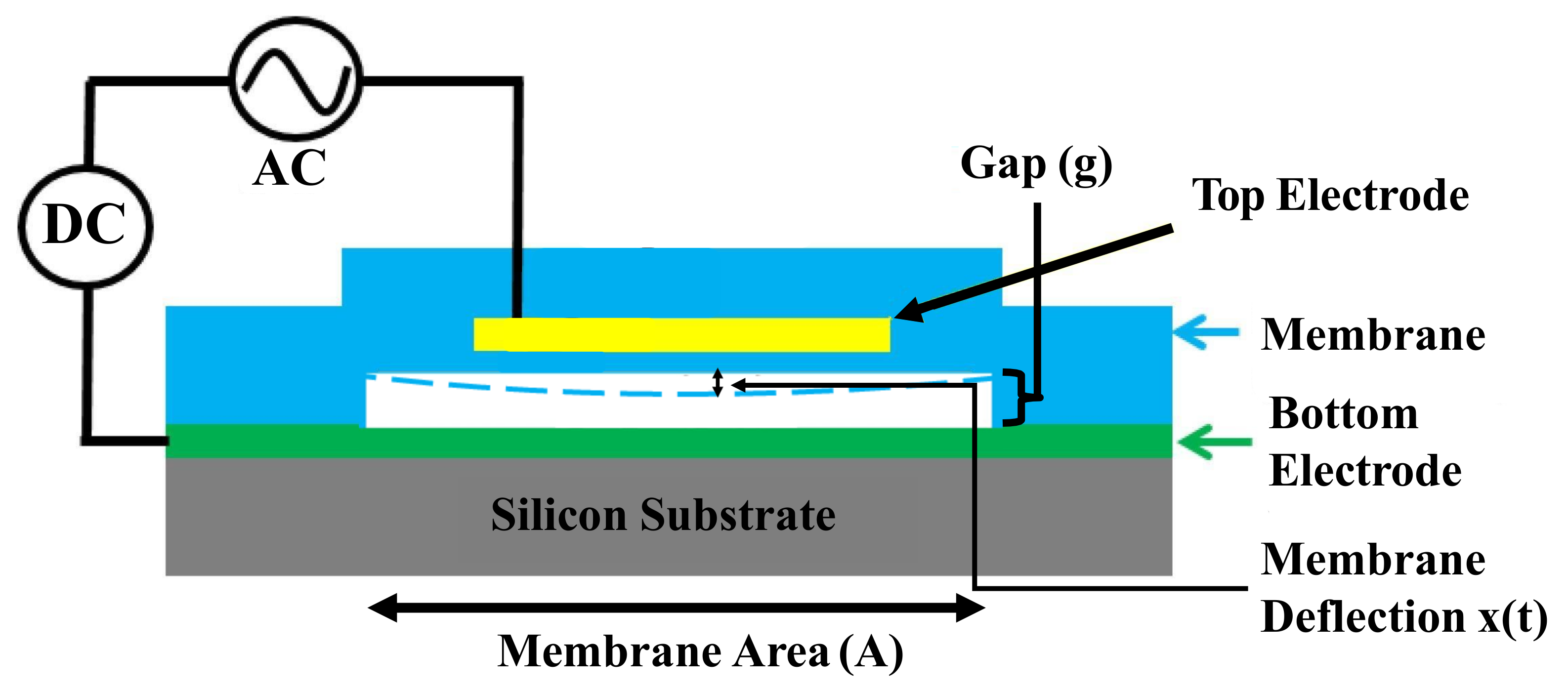
2. Operating Principle
3. Methods
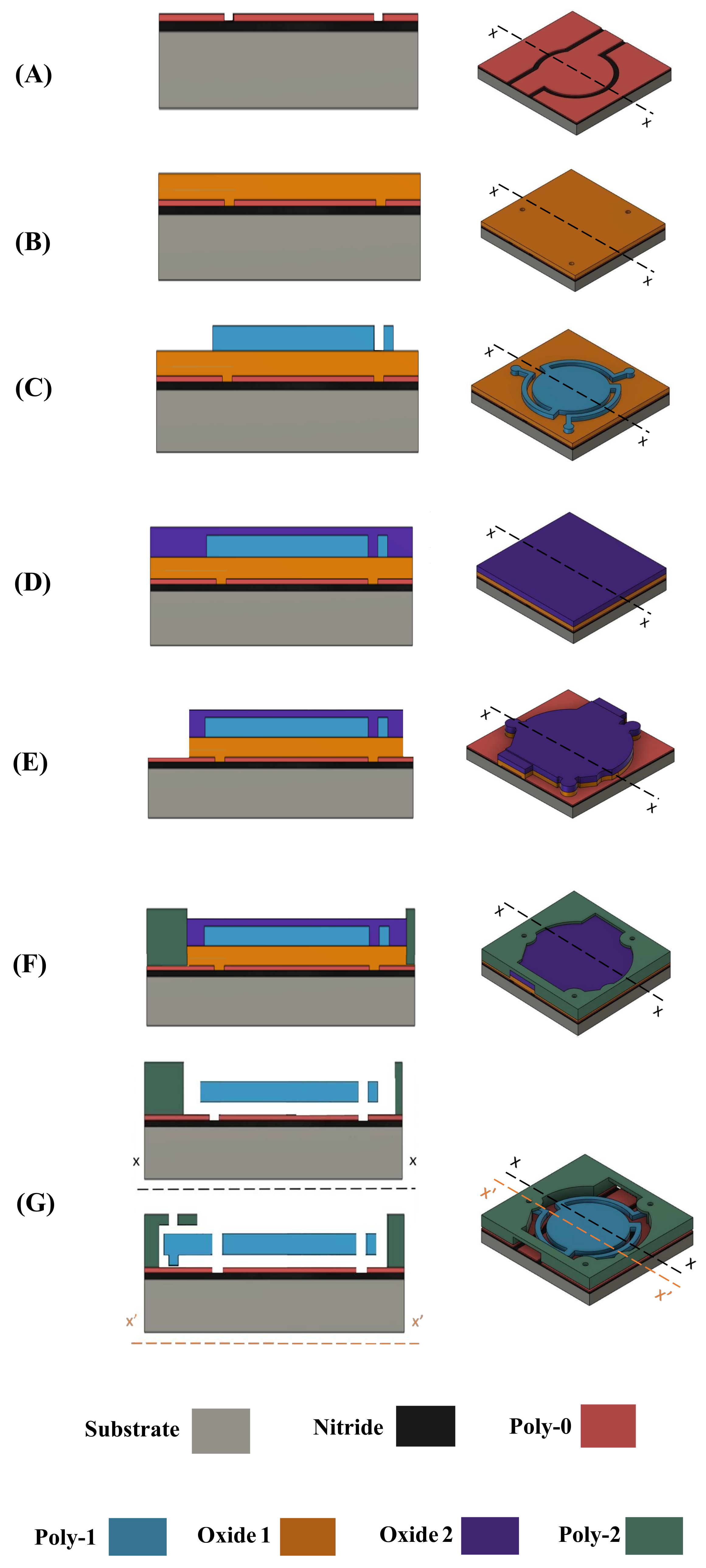
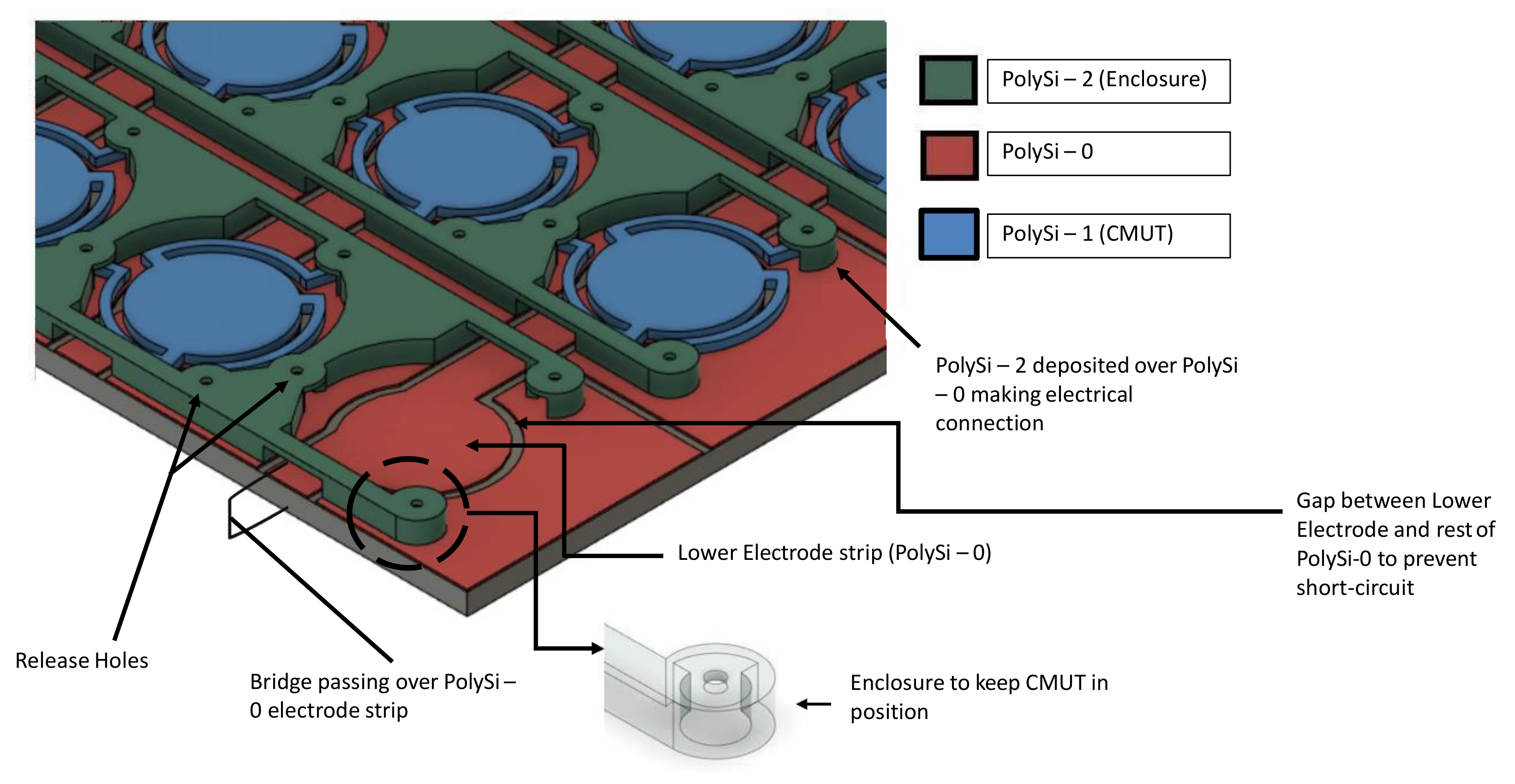
3.1. PolyMUMPS Fabrication
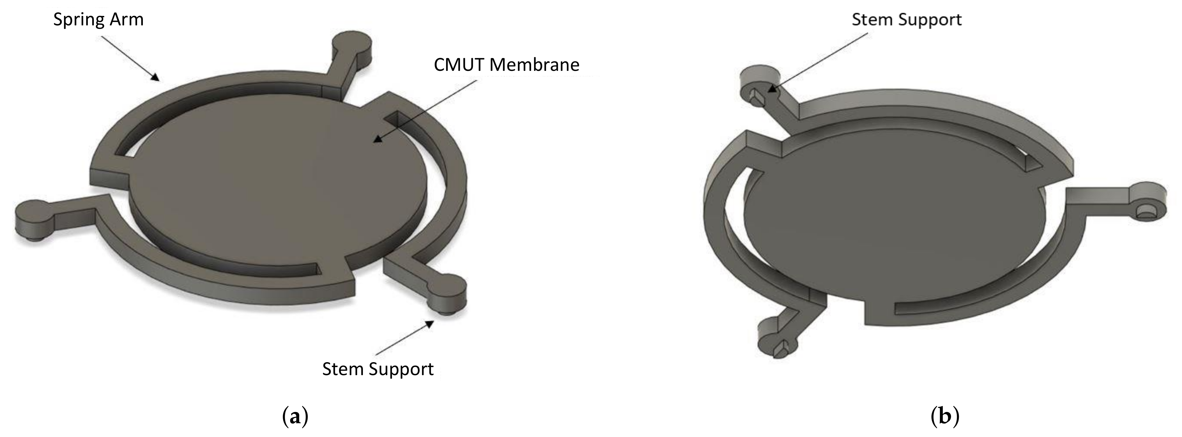
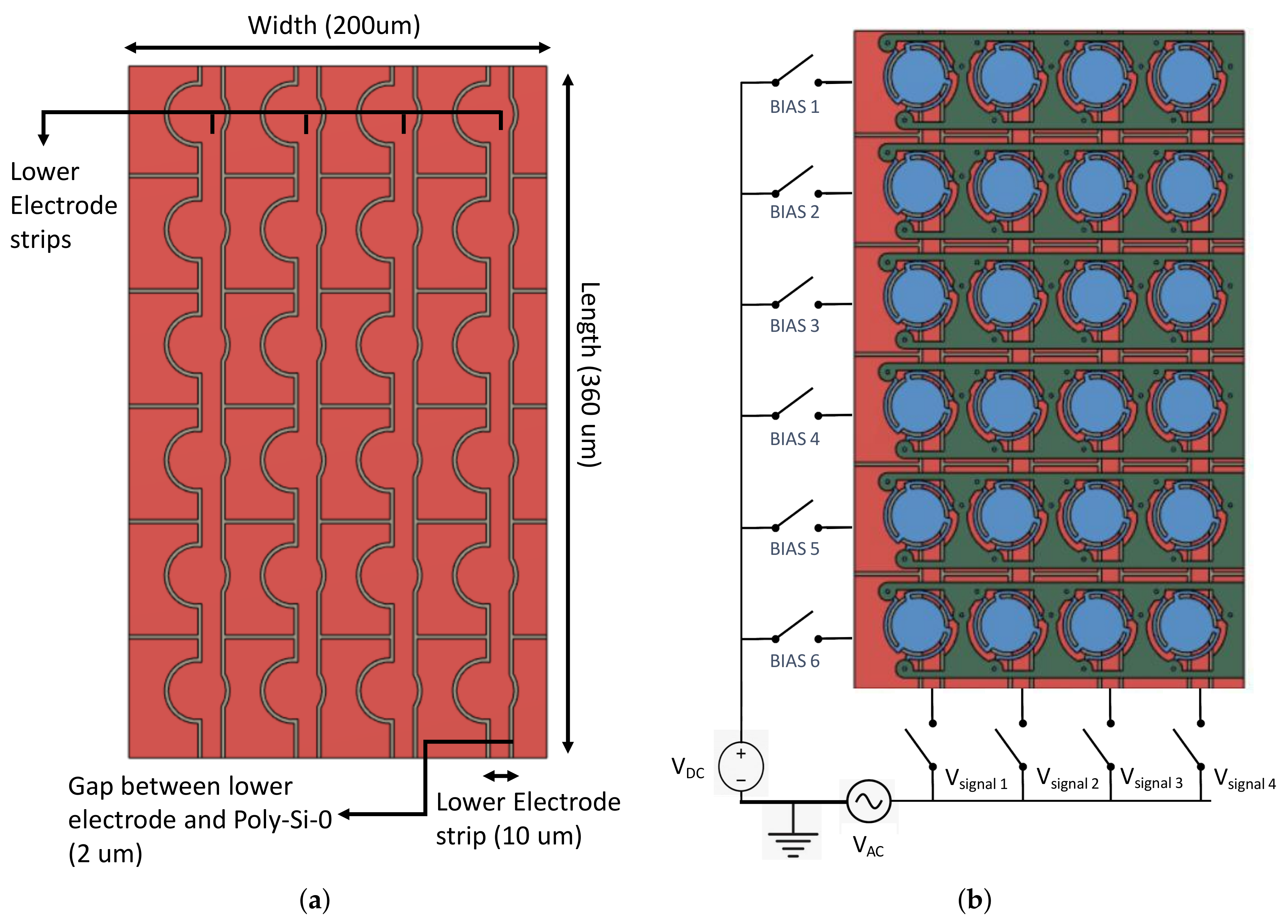
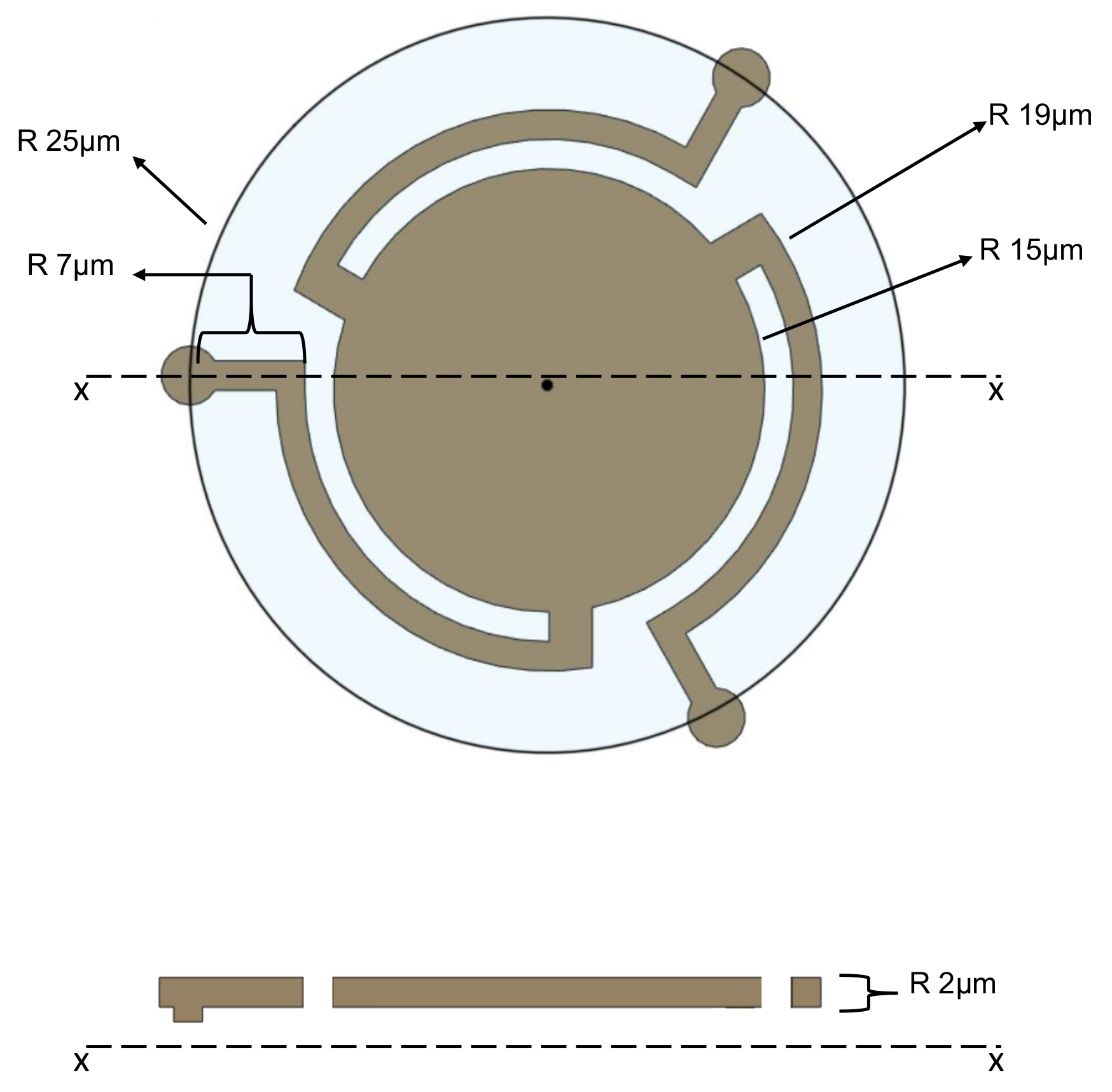
3.2. CMUT Cell Design
4. Results and Discussion
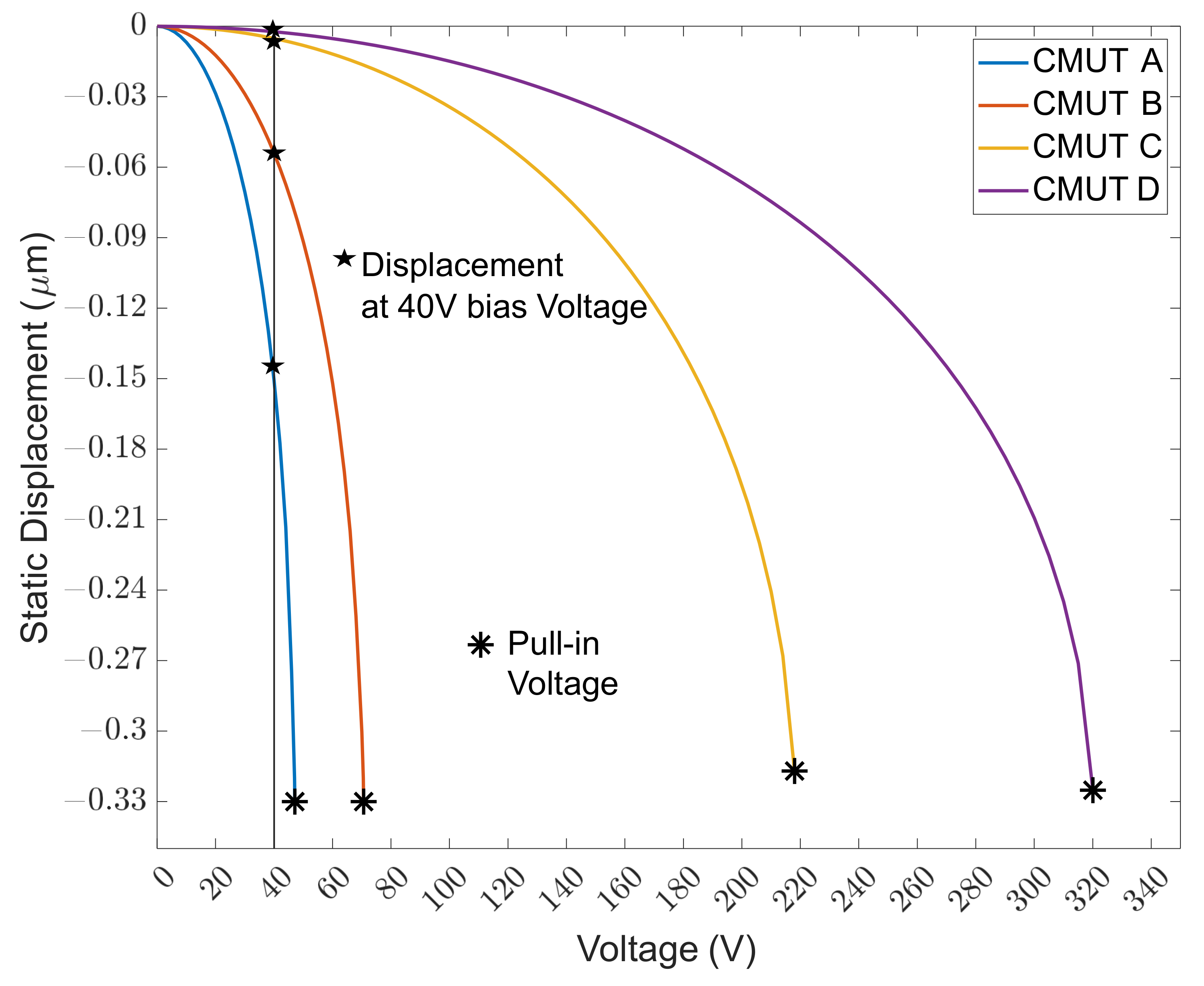
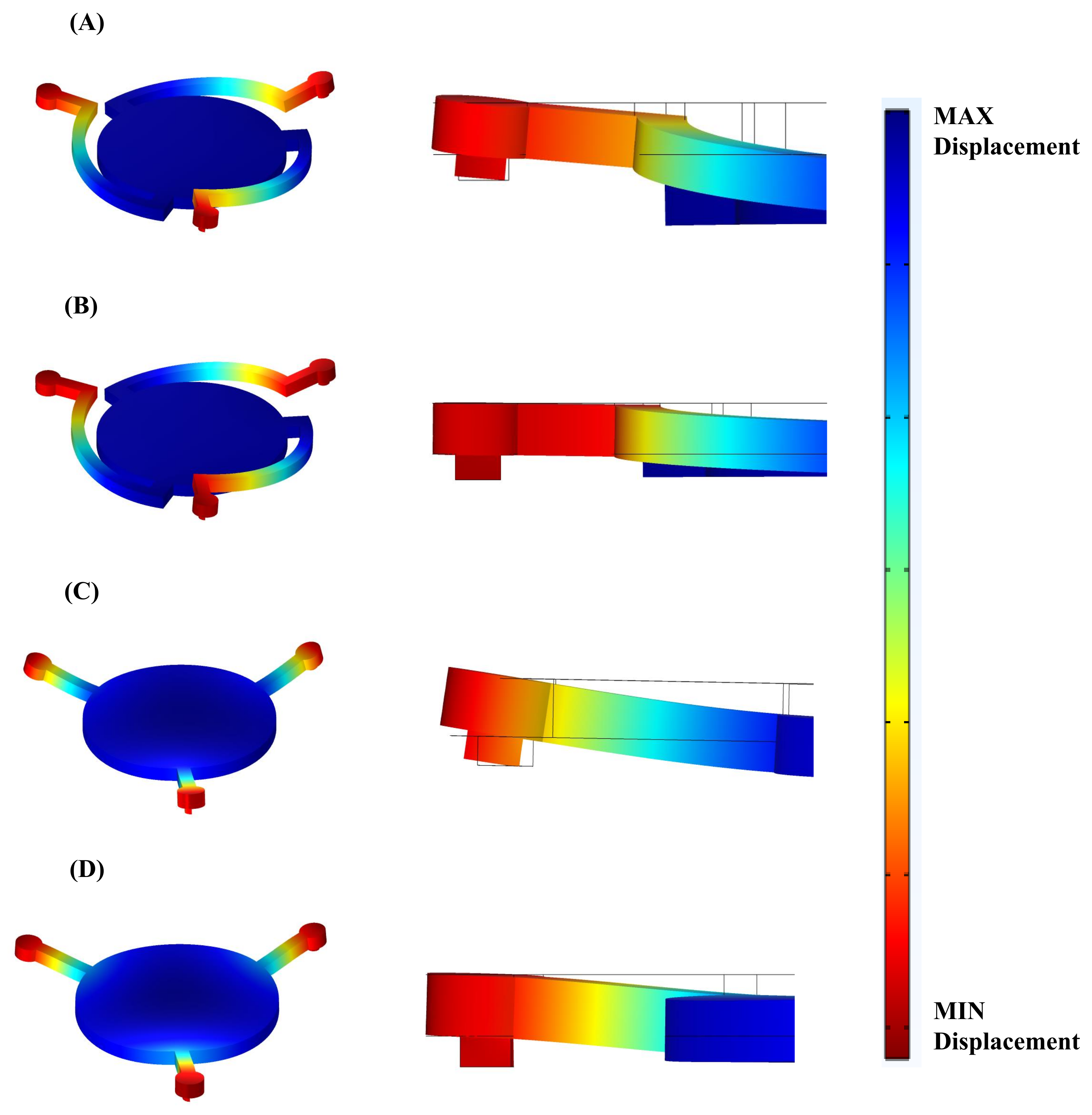
4.1. Static Simulation
4.2. Configuration and Parameters for Dynamic Simulation
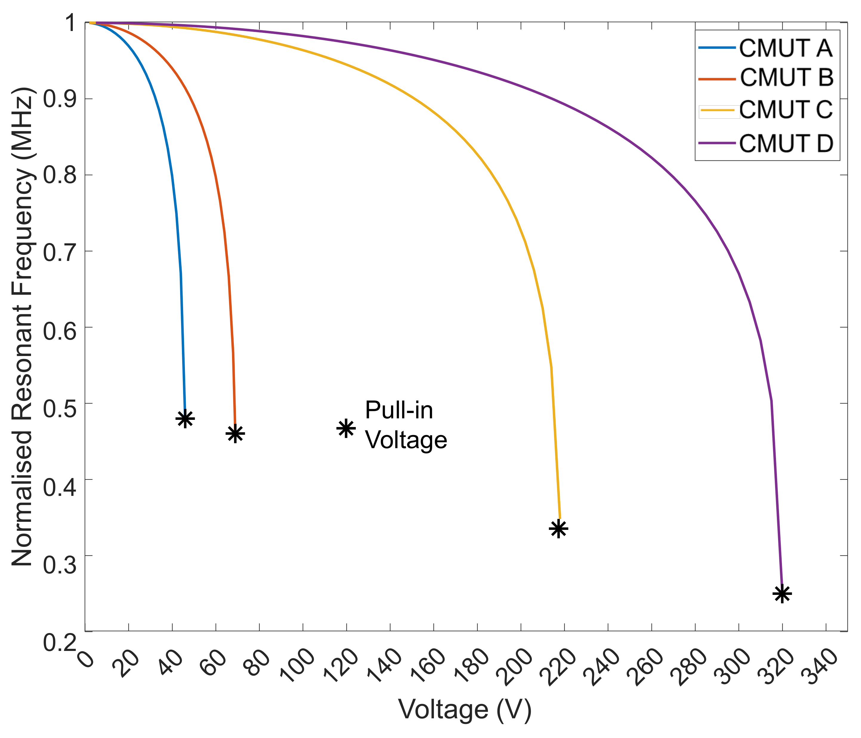
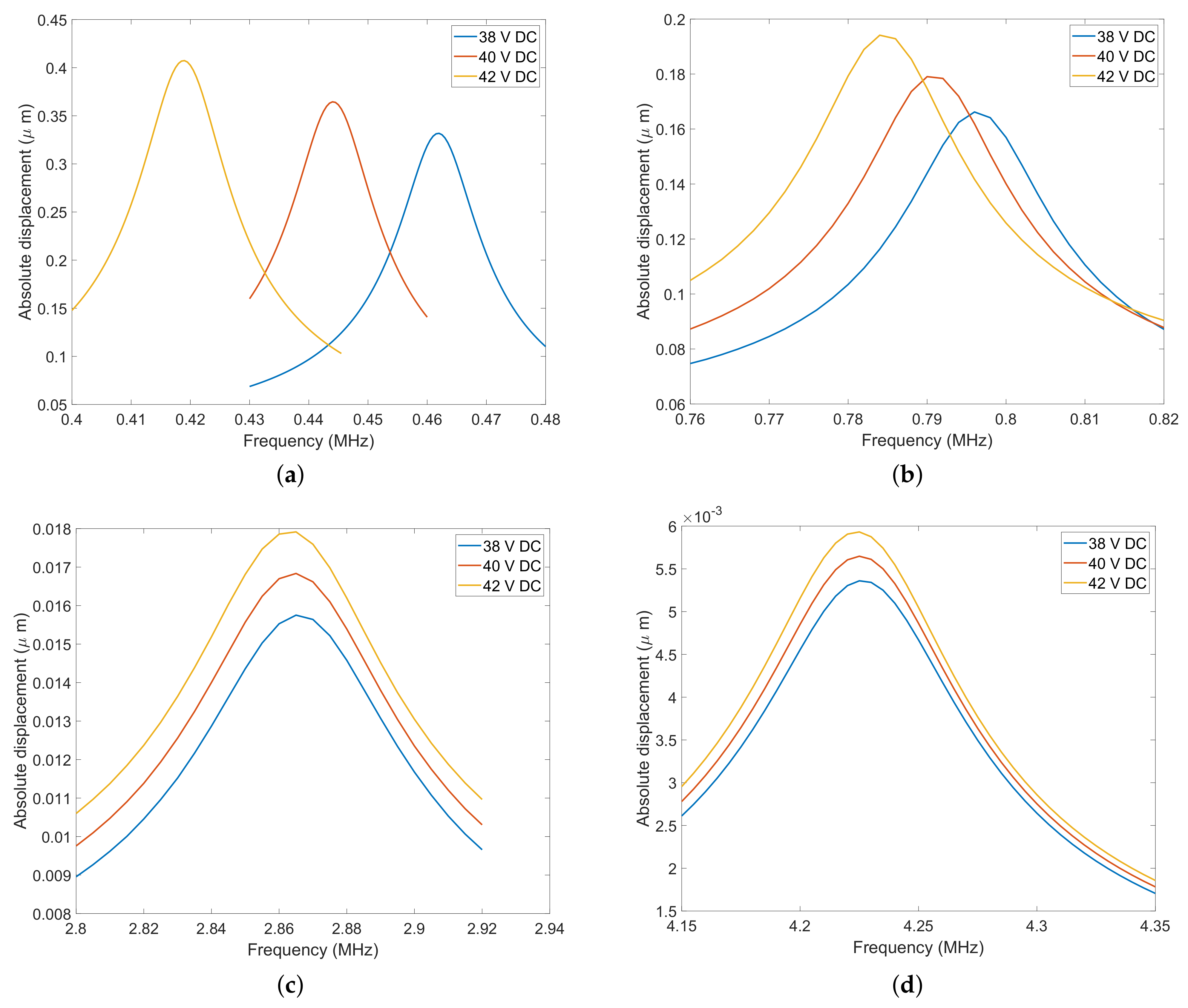
4.3. Harmonic Simulation
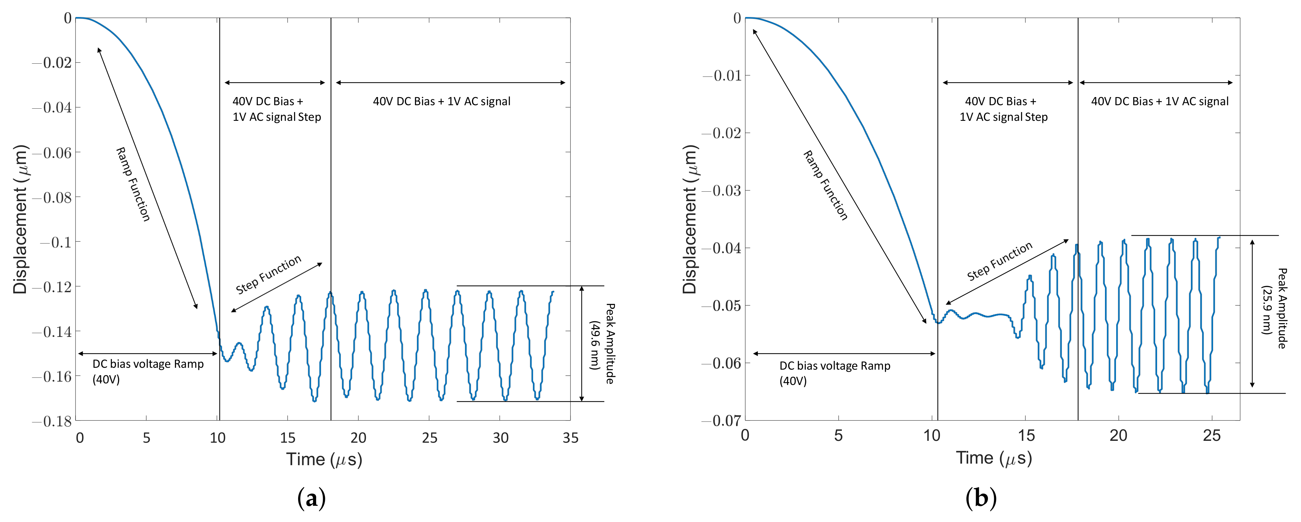
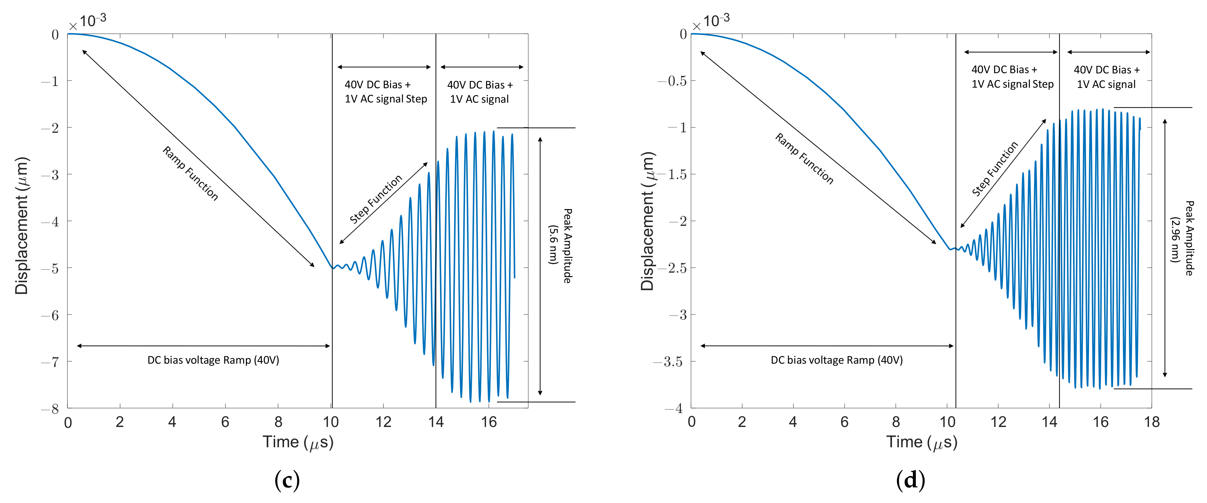
4.4. Dynamic Displacement
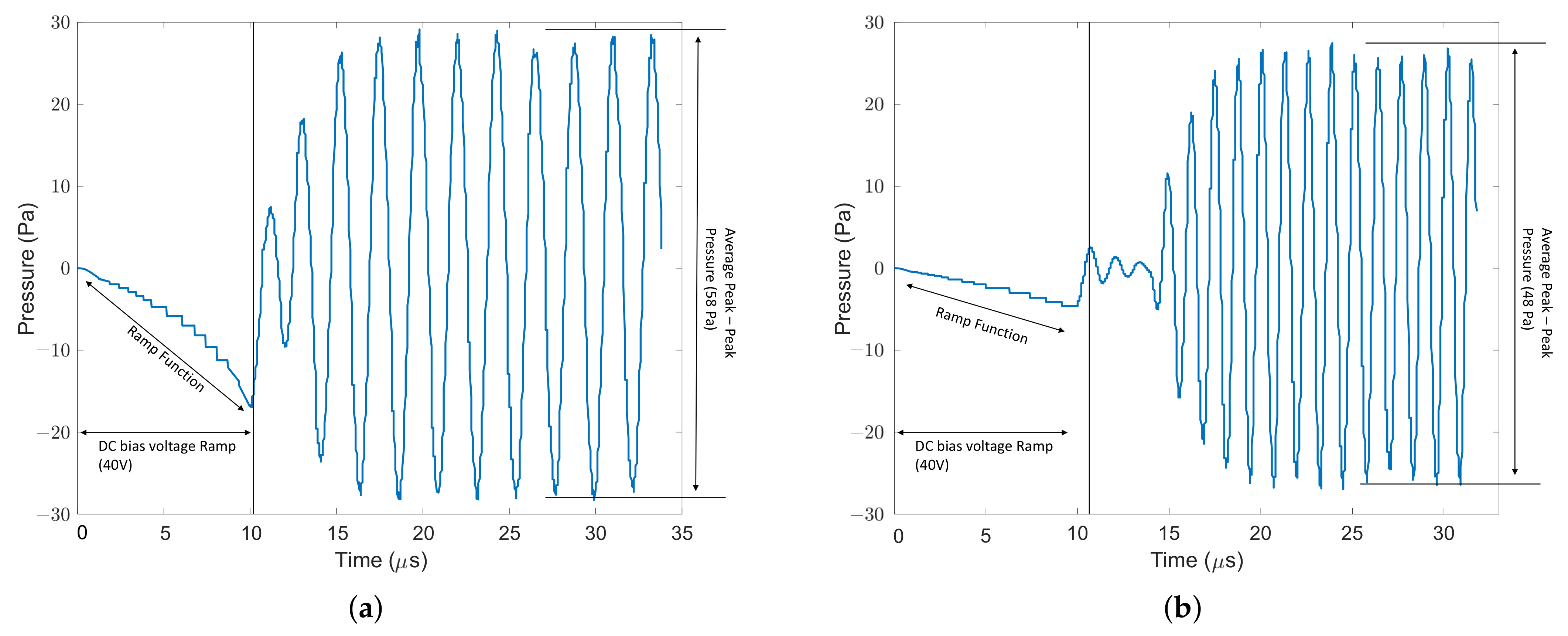
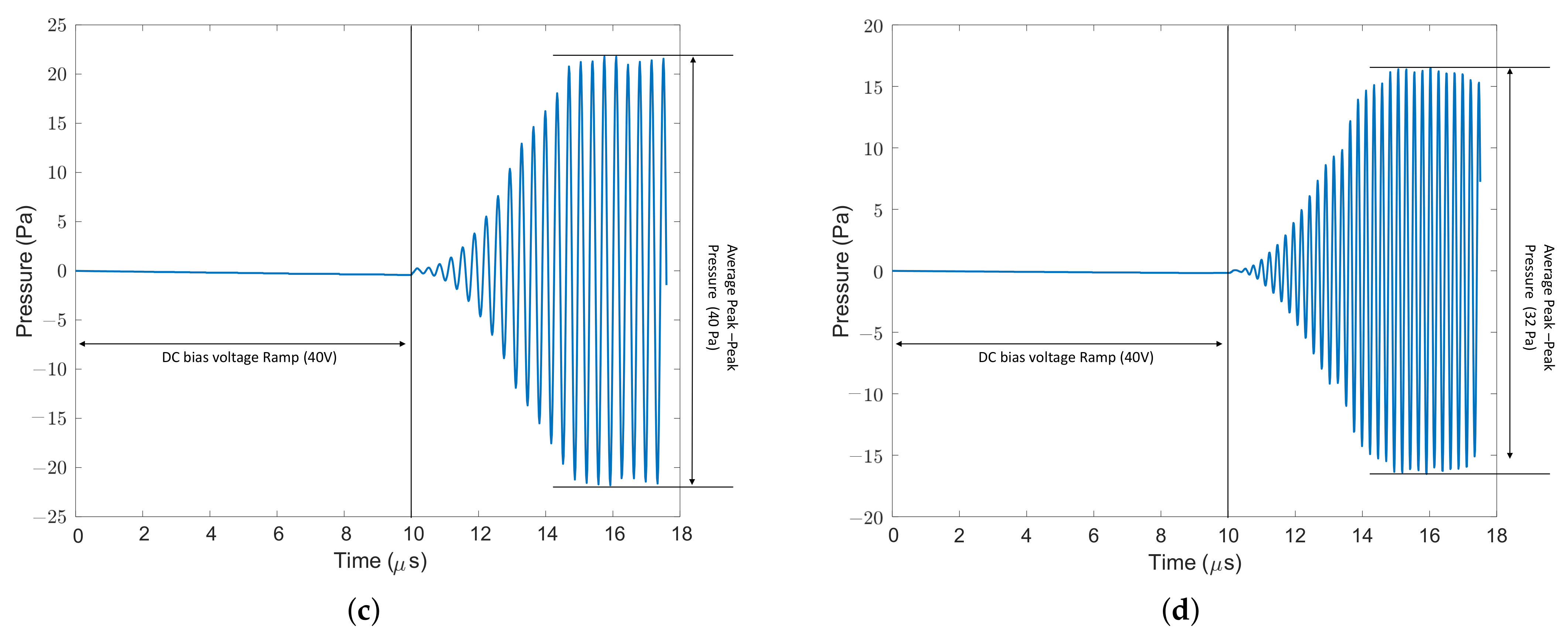
4.5. Dynamic Pressure
4.6. Displacement Efficiency
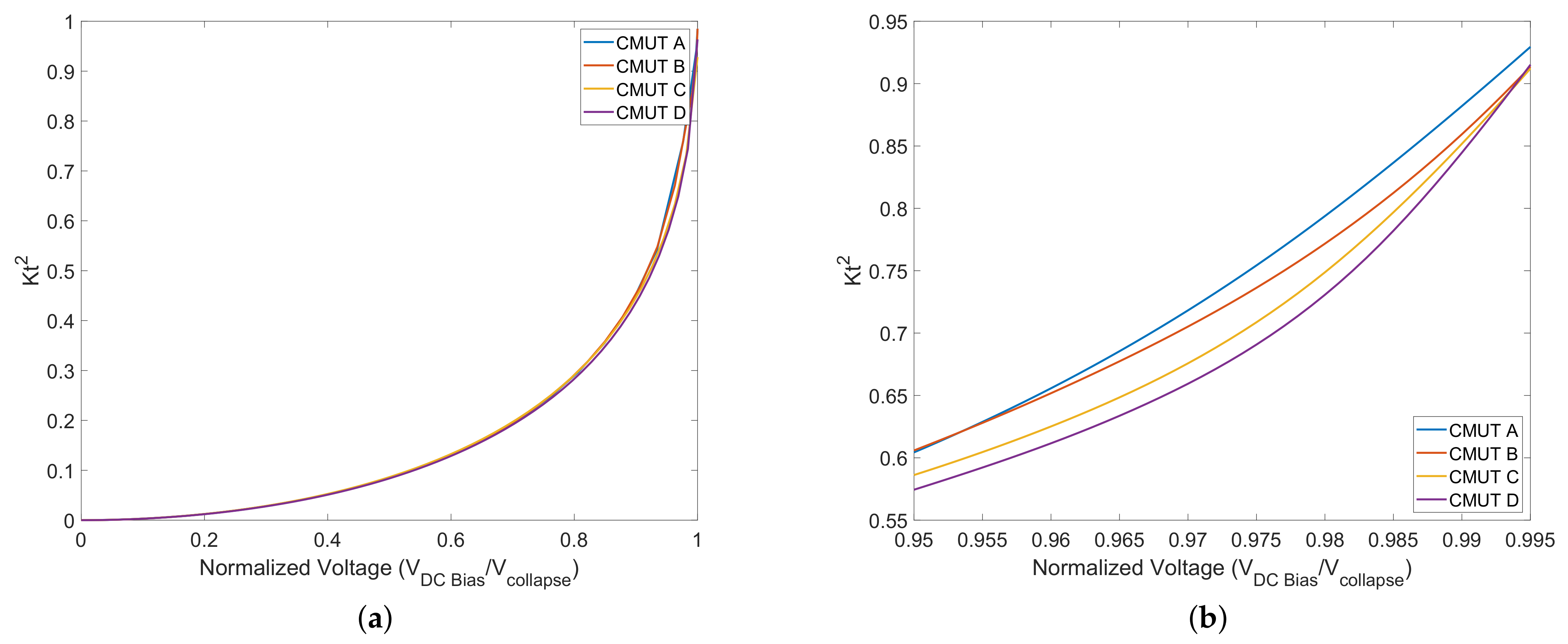
4.7. Electromechanical Coupling Coefficient
5. Conclusions
Author Contributions
Funding
Institutional Review Board Statement
Informed Consent Statement
Data Availability Statement
Acknowledgments
Conflicts of Interest
References
- Munir, J.; Ain, Q.; Lee, H.J. Reliability issue related to Dielectric Charging in capacitive micromachined Ultrasonic Transducers: A Review. Microelectron. Reliab. 2019, 92, 155–167. [Google Scholar] [CrossRef]
- Salim, M.S.; Malek, M.A.; Heng, R.; Juni, K.; Sabri, N. Capacitive Micromachined Ultrasonic Transducers: Technology and Application. J. Med. Ultrasound 2012, 20, 8–31. [Google Scholar] [CrossRef]
- Demirci, U.; Ergun, A.; Oralkan, O.; Karaman, M.; Khuri-Yakub, B. Forward-viewing CMUT arrays for medical imaging. IEEE Trans. Ultrason. Ferroelectr. Freq. Control. 2004, 51, 887–895. [Google Scholar] [CrossRef] [PubMed]
- Oralkan, O.; Ergun, A.; Cheng, C.H.; Johnson, J.; Karaman, M.; Lee, T.; Khuri-Yakub, B. Volumetric ultrasound imaging using 2-D CMUT arrays. IEEE Trans. Ultrason. Ferroelectr. Freq. Control. 2003, 50, 1581–1594. [Google Scholar] [CrossRef]
- Surappa, S.; Degertekin, F.L. Characterization of a parametric resonance based capacitive ultrasonic transducer in air for acoustic power transfer and sensing. Sens. Actuators A Phys. 2020, 303, 111863. [Google Scholar] [CrossRef]
- Rekhi, A.S.; Khuri-Yakub, B.T.; Arbabian, A. Wireless power transfer to millimeter-sized nodes using airborne ultrasound. IEEE Trans. Ultrason. Ferroelectr. Freq. Control. 2017, 64, 1526–1541. [Google Scholar] [CrossRef]
- Wang, J.; Liu, X.; Yu, Y.; Li, Y.; Cheng, C.H.; Zhang, S.; Mak, P.U.; Vai, M.I.; Pun, S.H. A Review on Analytical Modeling for Collapse Mode Capacitive Micromachined Ultrasonic Transducer of the Collapse Voltage and the Static Membrane Deflections. Micromachines 2021, 12, 714. [Google Scholar] [CrossRef]
- Bayram, B.; Oralkan, O.; Ergun, A.; Haeggstrom, E.; Yaralioglu, G.; Khuri-Yakub, B. Capacitive micromachined ultrasonic transducer design for high power transmission. IEEE Trans. Ultrason. Ferroelectr. Freq. Control. 2005, 52, 326–339. [Google Scholar] [CrossRef]
- Tawfik, H.H.; Alsaiary, T.; Elsayed, M.Y.; Nabki, F.; El-Gamal, M.N. Reduced-gap CMUT implementation in PolyMUMPs for air-coupled and underwater applications. Sens. Actuators A Phys. 2019, 294, 102–115. [Google Scholar] [CrossRef]
- Park, K.K.; Oralkan, O.; Khuri-Yakub, B.T. Comparison of conventional and collapse-mode CMUT in 1-D array configuration. In Proceedings of the 2011 IEEE International Ultrasonics Symposium, Orlando, FL, USA, 18–21 October 2011. [Google Scholar] [CrossRef]
- Pekař, M.; Dittmer, W.U.; Mihajlović, N.; Soest, G.V.; Jong, N.D. Frequency Tuning of Collapse-Mode Capacitive Micromachined Ultrasonic Transducer. Ultrasonics 2017, 74, 144–152. [Google Scholar] [CrossRef]
- Mao, S.; Rottenberg, X.; Rochus, V.; Nauwelaers, B.; Tilmans, H. FEM simulation and measurement validation of a CMUT cell. In Proceedings of the 2014 15th International Conference on Thermal, Mechanical and Mulit-Physics Simulation and Experiments in Microelectronics and Microsystems (EuroSimE), Ghent, Belgium, 7–9 April 2014. [Google Scholar] [CrossRef]
- Cowen, A.; Hardy, B.; Mahadevan, R.; Wilcenski, S. PolyMUMPs Design Handbook; Memscap Inc.: Crolles, France, 2011; Volume 13. [Google Scholar]
- Ma, B.; Firouzi, K.; Brenner, K.; Khuri-Yakub, B.T. Wide bandwidth and low driving voltage vented cmuts for airborne applications. IEEE Trans. Ultrason. Ferroelectr. Freq. Control. 2019, 66, 1777–1785. [Google Scholar] [CrossRef] [PubMed]
- Thacker, M.B.; Emadi, A.; Buchanan, D.A. Design, development, and characterization of a low frequency CMUT-based anemometer. IEEE Access 2021, 9, 127735–127741. [Google Scholar] [CrossRef]
- Zhang, H.; Liang, D.; Wang, Z.; Ye, L.; Rui, X.; Zhang, X. Fabrication and characterization of a wideband low-frequency CMUT array for air-coupled imaging. IEEE Sens. J. 2020, 20, 14090–14100. [Google Scholar] [CrossRef]
- Morse, P.M.; Ingard, K.U. Theoretical Acoustics; McGraw-Hill Book Co.: New York, NY, USA, 1968. [Google Scholar]
- Lee, B.; Nikoozadeh, A.; Park, K.; Khuri-Yakub, B. High-efficiency output pressure performance using capacitive micromachined Ultrasonic Transducers with substrate-embedded springs. Sensors 2018, 18, 2520. [Google Scholar] [CrossRef]
- Dahlberg, T. Procedure to Calculate Deflections of Curved Beams. Int. J. Eng. Educ. 2004, 20, 503–513. [Google Scholar]
- Deng, K.; Ko, W.H. A study of static friction between silicon and silicon compounds. J. Micromech. Microeng. 1992, 2, 14–20. [Google Scholar] [CrossRef]
- Park, K.K.; Lee, H.J.; Crisman, P.; Kupnik, M.; Oralkan, O.; Khuri-Yakub, B.T. Optimum design of circular CMUT membranes for high quality factor in air. In Proceedings of the 2008 IEEE Ultrasonics Symposium, Beijing, China, 2–5 November 2008; pp. 504–507. [Google Scholar] [CrossRef]
- Park, S.; Yoon, I.; Lee, S.; Kim, H.; Seo, J.W.; Chung, Y.; Unger, A.; Kupnik, M.; Lee, H.J. CMUT-based resonant gas sensor array for VOC detection with low operating voltage. Sens. Actuators B Chem. 2018, 273, 1556–1563. [Google Scholar] [CrossRef]
- Galisultanov, A.; Le Moal, P.; Bourbon, G.; Walter, V. Squeeze film damping and stiffening in circular CMUT with air-filled cavity: Influence of the lateral venting boundary conditions and the bias voltage. Sens. Actuators A Phys. 2017, 266, 15–23. [Google Scholar] [CrossRef][Green Version]
- Lu, Q.; Fang, W.; Wang, C.; Bai, J.; Yao, Y.; Chen, J.; Xu, X.; Huang, W. Investigation of a complete squeeze-film damping model for MEMS devices. Microsyst. Nanoeng. 2021, 7, 54. [Google Scholar] [CrossRef]
- Wu, G.; Xu, J.; Ng, E.J.; Chen, W. MEMS resonators for frequency reference and timing applications. J. Microelectromech. Syst. 2020, 29, 1137–1166. [Google Scholar] [CrossRef]
- Wang, Y.; Lin, Y.W.; Glaze, J.; Vukasin, G.D.; Shin, D.D.; Kwon, H.K.; Heinz, D.B.; Chen, Y.; Gerrard, D.D.; Kenny, T.W.; et al. Quantification of energy dissipation mechanisms in toroidal ring gyroscope. J. Microelectromech. Syst. 2021, 30, 193–202. [Google Scholar] [CrossRef]
- YASAR, A.I.; YILDIZ, F. Investigation of different membrane materials effects in CMUT membrane behaviour. In Proceedings of the 2019 3rd International Symposium on Multidisciplinary Studies and Innovative Technologies (ISMSIT), Ankara, Turkey, 11–13 October 2019. [Google Scholar] [CrossRef]
- Goyal, R.; Yadav, D. Design and Simulation of a MEMS-Based Capacitive Micro-Machined Ultrasonic Transducer for Viscosity Sensing Applications. 2018. Available online: https://www.comsol.it/paper/download/579421/goyal_paper.pdf (accessed on 7 July 2022).
- Ergun, A.S.; Yaralioglu, G.G.; Khuri-Yakub, B.T. Capacitive micromachined Ultrasonic Transducers: Theory and Technology. J. Aerosp. Eng. 2003, 16, 76–84. [Google Scholar] [CrossRef]


| Connecting Arm | Anchoring | |
|---|---|---|
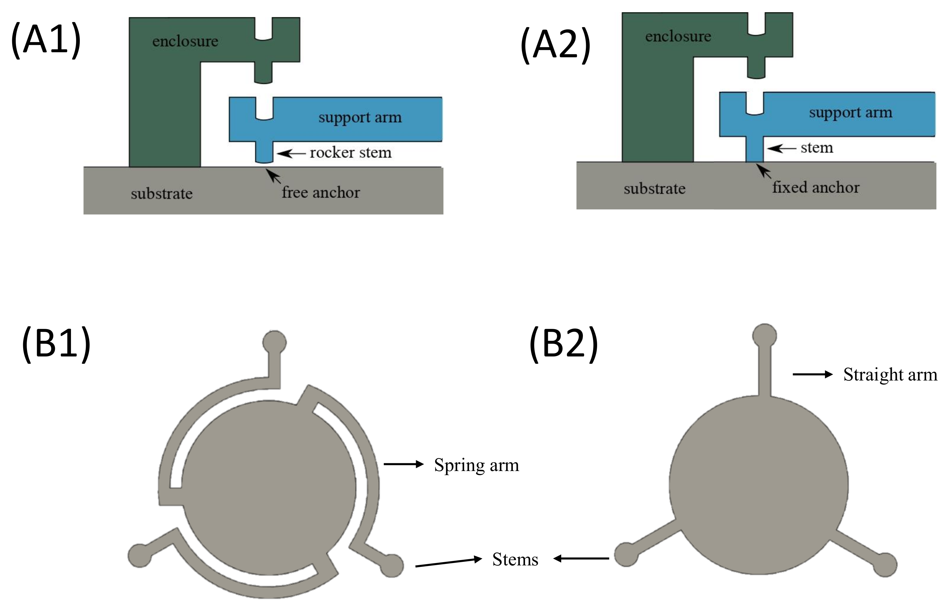
| CMUT A | Spring arm | Rocker support |
| CMUT B | Spring arm | Fixed anchoring |
| CMUT C | Straight arm | Rocker support |
| CMUT D (conventional) | Straight arm | Fixed anchoring |
| Layer | Thickness (um) |
|---|---|
| Nitride | 0.6 |
| Poly-0 | 0.5 |
| Oxide-1 | 2 |
| Poly-1 | 2 |
| Oxide-2 | 0.75 |
| Poly-2 | 1.5 |
| PolySi Young’s modulus (E) | 158 GPa |
| PolySi Modulus of rigidity (G) | 69 GPa |
| PolySi Poisson’s ratio (v) | 0.22 |
| PolySi density (σ) | 2230 kg/m |
| Rocket stem height (h) | 1 μm |
| Rocker stem radius (rd) | 1 μm |
| Diaphragm radius (r) | 30 μm |
| Diaphragm thickness (t) | 2 μm |
| Gap between electrode (g) | 1 μm |
| CMUT | P-P Pressure (Pa) | P-P Disp (nm) | Biased Resonant Frequency (MHz) | Pressure at 6 mm (Pa) | Pressure at 6 mm for Array (Pa) |
|---|---|---|---|---|---|
| A | 58 | 49.6 | 0.443 | 0.075 | 187.5 |
| B | 48 | 25.9 | 0.787 | 0.05 | 125 |
| C | 40 | 5.6 | 2.84 | 0.02 | 50 |
| D | 32 | 2.96 | 4.16 | 0.017 | 42.5 |
Publisher’s Note: MDPI stays neutral with regard to jurisdictional claims in published maps and institutional affiliations. |
© 2022 by the authors. Licensee MDPI, Basel, Switzerland. This article is an open access article distributed under the terms and conditions of the Creative Commons Attribution (CC BY) license (https://creativecommons.org/licenses/by/4.0/).
Share and Cite
Goel, C.; Cicek, P.-V.; Robichaud, A. Design and Implementation of Low-Voltage Tunable Capacitive Micro-Machined Transducers (CMUT) for Portable Applications. Micromachines 2022, 13, 1598. https://doi.org/10.3390/mi13101598
Goel C, Cicek P-V, Robichaud A. Design and Implementation of Low-Voltage Tunable Capacitive Micro-Machined Transducers (CMUT) for Portable Applications. Micromachines. 2022; 13(10):1598. https://doi.org/10.3390/mi13101598
Chicago/Turabian StyleGoel, Chirag, Paul-Vahe Cicek, and Alexandre Robichaud. 2022. "Design and Implementation of Low-Voltage Tunable Capacitive Micro-Machined Transducers (CMUT) for Portable Applications" Micromachines 13, no. 10: 1598. https://doi.org/10.3390/mi13101598
APA StyleGoel, C., Cicek, P.-V., & Robichaud, A. (2022). Design and Implementation of Low-Voltage Tunable Capacitive Micro-Machined Transducers (CMUT) for Portable Applications. Micromachines, 13(10), 1598. https://doi.org/10.3390/mi13101598