Thermomagnetic Convection of Ferrofluid in an Enclosure Channel with an Internal Magnetic Field


Abstract
1. Introduction
2. Governing Equations
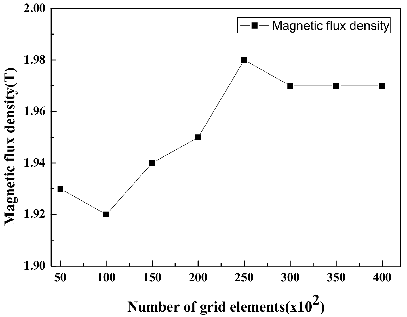
3. Numerical Analysis
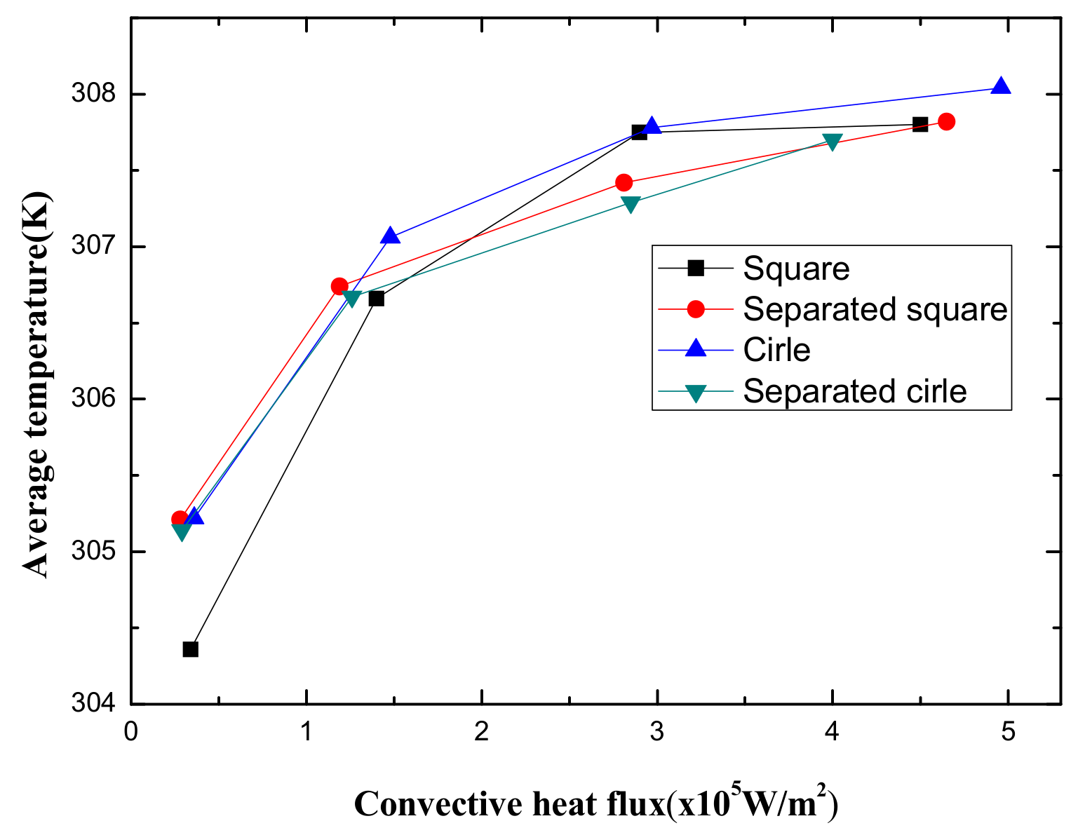
4. Results & Discussion
5. Conclusions
Author Contributions
Funding
Conflicts of Interest
References
- Rosensweig, R.E. Ferrohydrodynamics; Cambridge University Press: Cambridge, UK, 1985. [Google Scholar]
- Yu, P.X.; Qiu, J.X.; Qin, Q.; Tian, Z.F. Numerical investigation of natural convection in a rectangular cavity under different directions of uniform magnetic field. Int. J. Heat and Mass Transf. 2013, 67, 1131–1144. [Google Scholar] [CrossRef]
- Bibik, E.E.; Matgullin, B.Y.; Raikher, Y.L.; Shliomis, M.I. The magnetostatic properties of colloidal magnetite. Magnetohydrodynamics 1973, 9, 58–62. [Google Scholar]
- Janocha, H. Application potential of magnetic field driven new actuators. Sens. Actuators A 2001, 91, 126–132. [Google Scholar] [CrossRef]
- Afifah, A.N.; Syahrullail, S.; Sidik, N.A.C. Magnetoviscous effect and thermomagnetic convection of magnetic fluid: A review. Renew. Sustain. Energy Rev. 2016, 55, 1030–1040. [Google Scholar] [CrossRef]
- Blennerhassett, P.J.; Lin, F.; Stiles, P.J. Heat Transfer through strongly magnetized ferrofluids. Proc. R. Soc. Lond. A 1991, 433, 165–177. [Google Scholar] [CrossRef]
- Strek, T.; Jopek, H. Computer simulation of heat transfer through a ferrofluid. Phys. Status Solidi B 2007, 244, 1027–1037. [Google Scholar] [CrossRef]
- Aminfar, H.; Mohammadpourfard, M.; Zonouzi, S.A. Numerical study of the ferrofluid flow and heat transfer through a rectangular duct in the presence of a non-uniform transverse magnetic field. J. Magn. Magn. Mat. 2013, 327, 31–42. [Google Scholar] [CrossRef]
- Song, K.W.; Tagawa, T. Thermomagnetic convection of oxygen in a square enclosure under non-uniform magnetic field. Int. J. Therm. Sci. 2018, 125, 52–65. [Google Scholar] [CrossRef]
- Tangthieng, C.; Finlayson, B.A.; Maulbetsch, J.; Cader, T. Heat transfer enhancement in ferrofluids subjected to steady magnetic fields. J. Magn. Magn. Mat. 1999, 201, 252–255. [Google Scholar] [CrossRef]
- Yamaguchi, H.; Zhang, Z.; Shuchi, S.; Shimada, K. Heat transfer characteristics of magnetic fluid in a partitioned rectangular box. J. Magn. Magn. Mat. 2002, 252, 203–205. [Google Scholar] [CrossRef]
- Ghasemi, B.; Aminossadati, S.M.; Raisi, A. Magnetic field effect on natural convection in a nanofluid-filled square enclosure. Int. J. Therm. Sci. 2011, 50, 1748–1756. [Google Scholar] [CrossRef]
- Jiang, C.; Feng, W.; Zhong, H.; Zeng, J.Y.; Zhu, Q.M. Effects of a magnetic quadrupole field on thermomagnetic convection of air in a porous square enclosure. J. Magn. Magn. Mat. 2014, 357, 53–60. [Google Scholar] [CrossRef]
- Szabo, P.S.B.; Bekovic, M.; Früh, W.G. Using infrared thermography to investigate thermomagnetic convection under spatial non-uniform magnetic field Peter. Int. J. Therm. Sci. 2017, 116, 118–128. [Google Scholar] [CrossRef]
- Muller, H.W.; Engel, A. Dissipation in ferrofluid: Mecroscopic versus hydrodynamic theory. Phys. Rev. E. 1999, 60, 7001–7009. [Google Scholar] [CrossRef] [PubMed]
- Ganguly, R.; Sen, S.; Puri, I.K. Heat transfer augmentation using a magnetic fluid under the influence of a line dipole. J. Magn. Magn. Mat. 2004, 271, 63–73. [Google Scholar] [CrossRef]
- James, C.D.; McClain, J.; Pohl, K.R.; Reuel, N.; Achyuthan, K.E.; Bourdon, C.J.; Rahimian, K.; Galambos, P.C.; Ludwig, G.; Derzon, M.S. High-efficiency magnetic particle focusing using dielectrophoresis and magnetophoresis in a microfluidic device. J. Micromech. Microeng. 2010, 20, 04515. [Google Scholar] [CrossRef]


| Density | 1221 kg/m³ |
| Relative permeability of ferrofluid | 1.01 |
| Relative permeability of magnetite (Fe3O4) | 16 |
| Magnetic susceptibility | 1.552 |
| Dynamic viscosity | 0.00727 Pa∙s |
| Thermal conductivity | 0.19W/m∙K |
| Heat capacity at static pressure | 1840 J/kg∙K |
| Thermal expansion coefficient | 8.6 × 10⁻⁴ (1/K) |
| Working fluid | Ferrofluid |
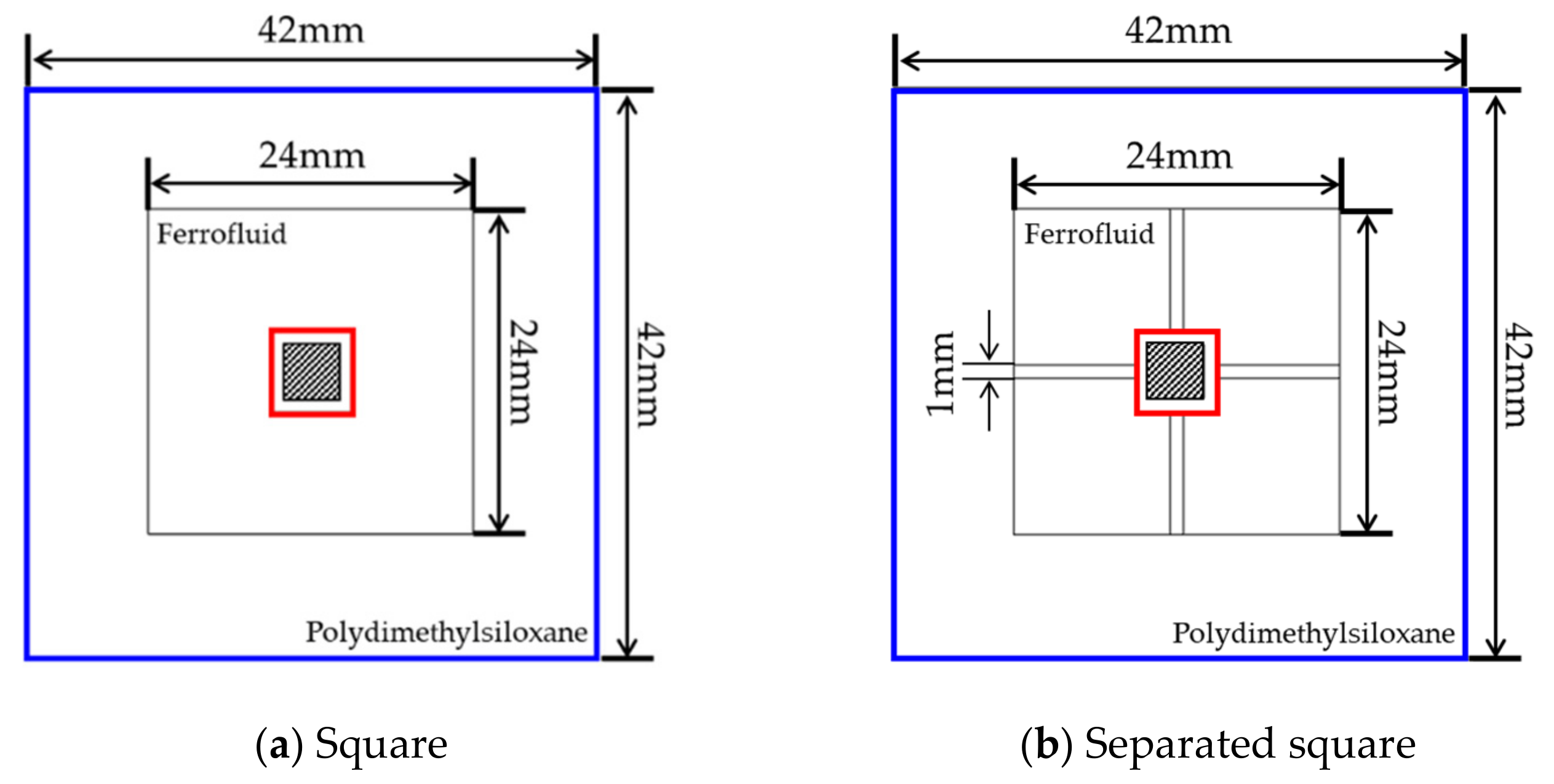
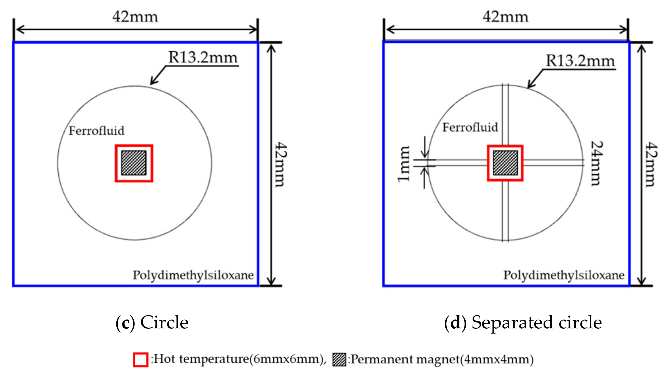
| Geometric configurations | Square, Separated square, Circle, Separated circle |
| Magnetic field strength, H | 1000–4000 (kA/m) |
| Directions of magnetic energy | Horizontal |
| Initial temperature | 293.15 K |
| Hot temperature (Heat source), Th | 313.15 K |
| Wall conditions of fluid domain | No-slip condition |
© 2019 by the authors. Licensee MDPI, Basel, Switzerland. This article is an open access article distributed under the terms and conditions of the Creative Commons Attribution (CC BY) license (http://creativecommons.org/licenses/by/4.0/).
Share and Cite
Lee, M.; Kim, Y.-J. Thermomagnetic Convection of Ferrofluid in an Enclosure Channel with an Internal Magnetic Field. Micromachines 2019, 10, 553. https://doi.org/10.3390/mi10090553
Lee M, Kim Y-J. Thermomagnetic Convection of Ferrofluid in an Enclosure Channel with an Internal Magnetic Field. Micromachines. 2019; 10(9):553. https://doi.org/10.3390/mi10090553
Chicago/Turabian StyleLee, Myoungwoo, and Youn-Jea Kim. 2019. "Thermomagnetic Convection of Ferrofluid in an Enclosure Channel with an Internal Magnetic Field" Micromachines 10, no. 9: 553. https://doi.org/10.3390/mi10090553
APA StyleLee, M., & Kim, Y.-J. (2019). Thermomagnetic Convection of Ferrofluid in an Enclosure Channel with an Internal Magnetic Field. Micromachines, 10(9), 553. https://doi.org/10.3390/mi10090553