Abstract
The inter-system-like bias between the regional (BDS-2) and global (BDS-3) constellation of the BeiDou Navigation Satellite System (BDS) has been identified on common B1I pseudo-range observations. In this study, its characteristics are investigated with tracking data from the International GNSS Service (IGS) and International GNSS Monitoring and Assessment System (iGMAS) network. Firstly, the satellite-specific inter-system-like bias is calculated and the dependency on satellite is observed. Clearly noticeable discrepancies on BDS-2 and BDS-3 can be identified. Hence, the constellation-specific inter-system-like bias is estimated. Biases for all receivers are quite stable, with standard derivation (STDev) less than 0.2 m in average. The bias shows clear dependence on the receiver, while the firmware and antenna have limited but not negligible impacts, particularly for Trimble NetR9 and Alloy receivers. The Trimble NetR9 with TRM59800.00 antenna shows noticeable discrepancy up to about 1.5 m with different antenna, and the bias of the Trimble Alloy 5.37 jumps about 2.4 m with respect to later firmware. In addition, clear annual variations are observed for stations ABPO and MIZU with Septentrio POLARX5 5.3.2 and ASTERX4 4.4.2 receivers, respectively. Furthermore, the impacts of the biases on the BDS orbit and clock solutions are analyzed. Once BDS-2 and BDS-3 are treated as two independent systems, the root mean square (RMS) of code and carrier phase residuals can be reduced by around 9.3 cm and 0.23 mm, respectively, while the three-dimensional orbit consistency is improved by 6.8%, mainly in the tracking direction. Satellite laser ranging (SLR) shows marginal impacts on IGSO and MEO satellites. However, the SLR residual of C01 shifts −13.2 cm, resulting in a smaller RMS value. In addition, the RMS of linear clock fitting is reduced from 0.050 ns to 0.038 ns for BDS-3 MEO satellites in average.
1. Introduction
The Chinese BeiDou Navigation Satellite System (BDS) has already been completely deployed to provide global position, navigation, and timing (PNT) services with more than 45 satellites. Among them, five geostationary earth orbit (GEO) satellites, seven inclined geosynchronous orbit (IGSO) satellites and three medium earth orbit (MEO) satellites make up the regional BDS-2 constellation, while the global BDS-3 constellation comprises three GEO, three IGSO, and twenty-four MEO satellites. According to Yang [1], BDS-2 satellites transmit a total of six signals in B1, B2, and B3 frequencies. The in-phase component of B1, B2 and B3 (B1I, B2I and B3I) is used for open service (OS) signals, while the other three are the authorized signals. Compared with BDS-2, BDS-3 satellites broadcast a total of eight signals. The B1 band signals include an OS B1C signal and an authorized service (AS) B1A signal, as well as a BDS-2 backward-compatible B1I signal at 1561.098 MHz. The B2 band transmits two OS signals, i.e., B2a at 1176.45 MHz and B2b at 1207.14 MHz. The B2b plus B2a signal forms a B2 signal on 1191.795 MHz. The B3 band contains an AS B3A signal centered at 1268.52 MHz, as well as the BDS-2-compatible B3I signal. These signals with new modulation strategies have advantages in signal interference and multipath resistance [2].
Regarding the distortion of BDS signals, BDS-2 satellites suffer the elevation-dependent group delay variations identified firstly by Wanninger and Beer [3], and the elevation-dependent piece-wise linear model is proposed to reduce their impacts on BDS data analysis. For BDS-3, the variations are significantly reduced to less than 0.1 m [4]. On the receiver side, the pseudorange biases for ionosphere-free (IF) combinations are estimated. Gong [5] identified that they are stable and dependent on both receiver type and satellite. With correction of the biases, the satellite clocks estimated by inhomogeneous receivers are much more in agreement with those estimated by the homogeneous receivers. Furthermore, the pseudorange biases on each single frequency are derived for BDS-2 satellites [6] to accelerate the convergence of precise point positioning (PPP) and to improve accuracy of standard point positioning (SPP). Most importantly, the consistency of wide-lane uncalibrated phase delay (UPD) among different stations is improved significantly, resulting in a 42% increase in the success rate of wide-lane ambiguity resolution. The receiver-correlated code biases for raw observations are also derived as per Zhang [7] with correction of other observation errors, and their analysis demonstrates that those biases on B1I and B3I signals differ by receiver and its firmware and antenna type, as well as unknown factors. The largest discrepancy can be up to 4 ns (about 1.2 m) between different receivers.
For multi-GNSS combined data analysis, the inter-system bias (ISB) should be considered to model the delays of signals of different GNSS systems on the receiver side. Usually, it is estimated as a GNSS-dependent constant. However, with data from the IGS (International GNSS Service) and iGMAS (International GNSS Monitoring and Assessment System) network, Li [8] observes that there is an obvious systematic bias between BDS-3 and BDS-2. Furthermore, the root of the bias is identified to be the inconsistency in pseudorange bias on the receiver side for the compatible B1I signal of BDS-2 and BDS-3 [9]. Additionally, the effects of ISB for standard point positioning (SPP), precise point positioning (PPP), and real-time kinematic (RTK) and time and frequency transfer application are evaluated [10,11,12,13,14,15].
The satellite-dependent code biases or the system-like biases between BDS-2 and BDS-3 on the receiver can distort combined BDS-2 and BDS-3 data analysis and degenerate the quality of orbit, clock, and other products. Li [16] has already applied the satellite-dependent code biases for BDS-2 precise orbit determination (POD), and the improved orbits were obtained, especially for GEO satellites. Beyond BDS-2 only, in this study, the system-like biases between BDS-2 and BDS-3 are analyzed. Their characteristics and impacts on the precise orbit and clock solutions are focused. The article is organized as follows. After the introduction, the data collection and availability are presented. Then, the strategy for ISB estimation and POD is summarized, and its characteristics as well as impacts on BDS orbit and clock solutions are evaluated. Finally, the study is concluded.
2. Data Collection
The tracking data from the IGS and iGMAS networks are used in this study. As reported by [17], the BDS-3 tracking capability of the IGS network is significantly enhanced in 2019, primarily due to receiver firmware updates. Additionally, some receivers have been replaced. Currently, the receivers with BDS-3 B1I and B3I tracking capability are mainly manufactured by Trimble, Javad, Leica, and Septentrio. Among them, the Trimble Alloy with firmware 5.42, Javad TRE_3 and TRE_3 DELTA with firmware 3.7.8, and Septentrio POLARX5 with firmware 5.4.0, and Leica GR30/50 with firmware 4.50 can track all active BDS-2 and BDS-3 satellites. The rest of the receivers can only track BDS-3 satellites with PRN up to C37 or C46. For iGMAS, the network consists of more than 30 stations around the world, and a total of seven types of receivers, i.e., BD070, gnss_ggr, CETC-54-GMR-4011, CETC-54-GMR-4016, UB4B0, UB4B0-13478, and UNICORE UB4B0I, made by four different Chinese manufacturers are deployed in tracking all OS signals from all BDS-2 and BDS-3 satellites. Table 1 lists the receivers and their firmware with B1I and B3I tracking capability, while Figure 1 shows their distribution on 30 August 2021.

Table 1.
Information on receivers and their firmware with BDS B1I and B3I tracking capability.
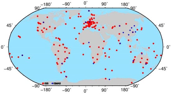
Figure 1.
The distribution of IGS (red point) and iGMAS (blue diamond) stations with BDS B1I and B3I tracking capability on 30 August 2021.
As aforementioned, all BDS-2 satellites can be tracked by IGS stations, whereas the BDS-3 tracking capability of IGS stations is dependent on the receiver type as well as the firmware version. Hence, the available observations for BDS-3 satellites vary with time. Generally, the later the satellites are launched, the fewer observations are available. Figure 2 shows the daily number of tracking stations for some groups of BDS-3 satellites listed in Table 2 during the selected period, i.e., day of year (DOY) 001, 2019 to DOY 150, 2021. The satellites in each group can be tracked by the same receivers. It can be seen that the number of tracking stations increases gradually due to the updates of IGS as well as iGMAS stations. Two jumps can be observed around DOY 30, 2019 and 62, 2020 thanks to the updates of receiver firmware (Trimble NetR9, and Septentrio POLARX5). It should be noted that a relatively rapid increase occurs in the second half of 2019 for C23 and C35 due to deployment of more Septentrio receivers, as well as at the beginning of 2021 for the satellites with PRN beyond 37, as the firmware and decoding software of more Septentrio receivers were updated. Overall, more than 180 stations were able to track the satellites with PRN before PRN 37 in the middle of 2021, whereas there are about 100–130 stations available for the rest of the satellites.
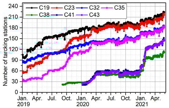
Figure 2.
The daily number of tracking stations for each BDS-3 satellite group listed in Table 2 from DOY 001, 2019 to DOY 150, 2021.
Table 2.
The groups for BDS-3 satellites classified according to the number of tracking stations.
3. Method and Strategy
3.1. Method
The raw GNSS observation equations for pseudorange and phase on the frequency in unit of length from station to satellite take the form of
where denotes the station–satellite geometric distance; is the zenith tropospheric delay (ZTD) with mapping function ; and are the receiver and satellite clock offsets; represents the slant ionospheric delay; and denotes the scaling coefficients equating to , where is the frequency with wavelength and and are the hardware biases at station for code and phase, and viewed as frequency- and receiver-dependent constant, whereas and are those at satellite . denote the integer ambiguity parameter and and are the noise of code and phase measurements. For brevity, the multipath errors, phase windup, satellites and receiver antenna phase center corrections, relativistic effect, and station tides corrections are ignored.
Usually, for orbit determination, the IF combination of code and phase observations is used and expressed as follows:
where is the frequency for the second signal and the rest can be obtained as follows:
Those biases are linearly correlated with each other and clock as well as ambiguity parameters. To remove the rank deficient, re-parameterization is required. Usually, these code biases on the satellite and receiver are assimilated by the corresponding clock parameters, whereas the phase biases are absorbed by ambiguity. Finally, the observation equations for orbit determination are obtained:
where and represent the reparametrized clocks equal to and , respectively.
For multi-GNSS data analysis, the inter-system bias (ISB) should be considered to model the different code bias on the receiver for different GNSS systems. Usually, it is treated as a system-dependent constant. However, Mi demonstrates that ISB also shows the temperature sensitivity [18]. In this study, this behavior is immaterial. With the GPS-derived receiver clock as the reference, the code and phase observation equations for satellite of BDS can be expressed as
where denotes the BDS system, and * can be 2 or 3 for BDS-2 and BDS-3 or for the satellite in cases where it is viewed as a satellite-dependent instead of a system-specific parameter. is the ISB between the GPS and BDS systems or one BDS satellite. As the receiver clock is highly related to , the datum should be introduced. In this study, the sum of on all sites for each satellite or all BDS-2 satellites or all BDS-3 satellites are constrained to zero to reduce the rank deficiency.
As shown by [9], there are inter-system-like biases between BDS-2 and BDS-3. Hence, two ISB parameters are recommended to be estimated when they are combined for data analysis. Moreover, these can be estimated for each BDS satellite. If only one ISB, labeled as , is estimated, Equation (5) can be rewritten in the following form for BDS-2 and BDS-3, respectively
In the above equation, and cannot be absorbed by any common parameters in the code observation equation. They are left to residuals for code, but will be absorbed by ambiguity for phase. A similar observation equation can be obtained when the satellite-specific bias is estimated. It should be noted that ISBs act only on code observation and do not affect the phase observation.
Phase ambiguity fixing is crucial for improving the solutions’ accuracy. The ambiguity of the IF combination is not an integer, and can commonly be expressed as the combination of wide-lane and narrow-lane. In this study, overlapping frequencies of B1I and B3I are used, and the double-difference (DD) method is carried out between two satellites and two receivers sequentially, where the common errors are eliminated in the equation. As the DD ambiguities are formed, the ISBs only cause deviation in code observation, and the estimates for inter-system DD IF ambiguities are not impacted by the ISB. The double-difference wide-lane (WL) ambiguity is estimated with the MW method using the corresponding phase and range observations [19,20,21]. The double-difference narrow-lane (NL) estimate can be obtained with the fixed double-difference wide-lane ambiguity by the following relationship:
where is the double-difference IF ambiguity of satellite , and receiver , . However, these biases cannot be completely removed for wide-lane estimated with the MW method:
where represents satellite, which can be expressed by and ; represents receiver, and can be expressed by and ; are the combined effects of the code and phase observation bias related to the satellite; and are those for receiver. For double-difference combination between two satellites and two receivers, the satellite- and receiver-specific bias can be eliminated in intra-constellations of BDS-2 or BDS-3 only. However, if the inter-constellations between BDS-2 and BDS-3 are involved, the bias cannot be eliminated as there is code ISB between BDS-2 and BDS-3. Then, the double-difference wide-lane combination between BDS-2 and BDS-3 satellites derived from MW combination can be expressed as:
where the subscripts and are the two stations, and are the ISBs of frequency for BDS-2 and -3 on receiver , and and are the parameters for receiver b. As is station-dependent, it cannot be removed by differences between sites. As mentioned above, the estimated DD IF combination ambiguity is unaffected. Hence, the incorrectly fixed DD WL ambiguity will be partly compensated by DD NL ambiguity, resulting in wrong ambiguity resolution. For correct WL ambiguity resolution between BDS-2 and BDS-3, the fractional bias caused by the ISB-like bias should be calibrated. This has already been done by [22]. In this study, we focus only on the impacts of ISB-like bias on orbit and clock by treating BDS-2 or BDS-3 as two independent constellations or the one, as some analysis centers do for generation of orbit and clock products of BDS.
3.2. Strategy
The data during DOY 001, 2019 to DOY 150, 2021 are selected for analysis, and the two-step approach is used. First, the IGS GPS final clock and orbit products as well as Earth Orientation Parameters (EOPs) from the IERS (International Earth Rotation Service) EOP 14 C04 (IAU2000A) are fixed to estimate the coordinates, receiver clock and zenith troposphere delay (ZTD) of tracking stations with precise point positioning (PPP). Afterwards, these parameters are fixed for precise BDS-2 and BDS-3 orbit as well as clock determination with simultaneous estimation of satellite- or constellation-dependent ISB. The measurement and dynamic models are summarized in Table 3. To investigate the characteristics of the biases and their impacts on the orbit and clock solutions of BDS-2 and BDS-3, it has been clarified that the obvious ISB bias between BDS-2 and BDS-3 should be parameterized and the influence of ambiguity resolution needs to be tested. Hence, five solutions are determined, as follows.
Table 3.
Measurement and dynamic models used for data analysis in this study.
- BNA0 solution: The satellite-specific ISB is estimated for each BDS satellite with float ambiguity resolution.
- B1A1 solution: One ISB is estimated for both BDS-2 and BDS-3 with inter-constellation integer ambiguity resolution.
- B2A1 solution: Two ISB values are estimated for BDS-2 and BDS-3 independently with inter-constellation integer ambiguity resolution.
- B1A2 solution: One ISB is estimated for both BDS-2 and BDS-3 with intra-constellation integer ambiguity resolution.
- B2A2 solution: Two ISB values are estimated for both BDS-2 and BDS-3 with intra-constellation integer ambiguity resolution.
4. Experiments and Discussion
4.1. Characteristics of Inter-System-like Bias
The data from 117 stations of IGS MGEX and iGMAS network are analyzed. Table 1 lists their receiver and firmware information, and there are 60 types of receiver and firmware pairs in total. In this section, the estimates of ISB are analyzed. Firstly, the BNA0 solution is used, and the characteristics of satellite-specific ISBs for all non-GEO satellites are investigated. Although the zero constraint has been added to remove the rank deficiency from the high correlation between receiver clock and ISB, the raw estimates of ISB show clear variations dependent on the number of sites with the satellite tracking capability. Hence, KIR8 is selected as the datum to remove the variation by differentiating the raw ISB parameters with respect to the estimated satellite-specific ISB parameters of the reference station. The details are shown in Figure 3 for site WUH2. Here, we plot the ISBs for BDS-2 satellites in black, whereas the red dots represent those for BDS-3 satellites. The satellite-specific ISBs are also plotted in the subfigure. It can be observed that there is obvious bias in the estimates of ISB for BDS-2 and BDS-3, and a jump occurs at 9 October 2019 due to the replacement of the Trimble NetR9 receiver by the Trimble Alloy for the reference site. The standard derivation (STDev) of all BDS-2 satellite-dependent with Trimble NetR9-referenced ISBs is about 0.71 m, while it is 0.42 m for that of BDS-3.
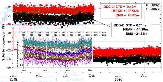
Figure 3.
The time series of daily estimated satellite-specific ISB for station WHU2 by taking KIR8 as the reference, where the black and red points represent that of BDS-2 and BDS-3 satellites, respectively. The details on satellite-specific ISB are also plotted in the bottom-left subfigure.
Deep investigation on the satellite-specific bias is carried out, and the clear satellite dependency can be recognized, particularly for BDS-2. A similar phenomenon can be found in the study of [29], and it is termed “signal distortion”. With the correction of the signal distortion bias, the root mean square (RMS) of the pseudorange residuals and double-difference slant total electron content (STEC) are decreased for different satellite systems in their study. From the estimates of the satellite-specific ISB, it can be observed that the ISB parameters of BDS-2 and BDS-3 cluster obviously have better data stability (STDev). Hence, the subsequent analysis is entirely based on estimating one or two ISB parameters.
In this study, we focus on the system-like bias between BDS-2 and BDS-3. Hence, their characteristics are analyzed in the following parts. Here, the double difference is employed to derive the relative bias of ISB parameters between BDS-2 and BDS-3. Firstly, the difference between stations is determined so as to remove its impact on data. Second, the ISBs of BDS-2 and BDS-3 are further differentiated. The B2A1 solution is used for the analysis, and other solutions show a similar phenomenon. It should be noted that those estimates from ASCG are selected as the reference due to good BDS-3 tracking capability during the selected period. The Trimble NetR9 receiver is used at ASCG before DOY 082, 2021, while the Trimble Alloy receiver is used in the rest period. Figure 4 shows the time series of the daily bias for eight selected stations equipped with different types of receivers. Here, only the results in the period without changes in equipment are plotted. Generally, the biases are different for each station, but relatively stable. Bias reaches about 4.05 m for LMMF, whereas it is only −0.42 m for AREG. LMMF has the largest variations among the eight stations, and the STDev of the daily bias reaches 0.37 m, while it is below 0.2 m for the rest of the stations. Additionally, the impacts of the reference station on the value of the system-like bias can be clearly observed, as those of BJF1, KIR8, and BYNS show noticeable jumps once the receiver of ASCG is updated to the Trimble Alloy. However, the differences in bias between those stations remain stable.
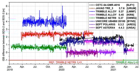
Figure 4.
The daily values of inter-system-like bias between BDS-2 and BDS-3 for the selected eight stations.
Although the system-like bias between BDS-2 and BDS-3 is quite stable for most stations, annual variations are identified in the biases of ABPO as well as SEPT equipped with Septentrio POLARX5 5.3.2 and ASTERX4 4.4.2, respectively, as shown in Figure 5. ABPO is located in Madagascar, in the Southern Hemisphere, while MIZU is in Japan, in the Northern Hemisphere. For MIZU, the greatest bias appears in August and the lowest value appears in January, where there is about a three-month delay for ABPO. The reason behind this needs further investigation.
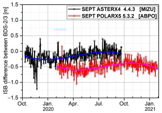
Figure 5.
The daily values of inter-system-like bias between BDS-2 and BDS-3 for MIZU, located in the Southern Hemisphere, and ABPO, located in the Northern Hemisphere. The solid blue and pink lines are the fitting trend.
To investigate the dependency of the bias on firmware, the daily values are plotted in Figure 6 for station SOD3 equipped with a Javad TRE_3 DELTA receiver. During the selected period, its firmware has been updated three times. ABPO equipped with a Septentrio POLARX5 receiver is used as the reference site, and there are five firmware versions. It can be observed that the bias is quite stable during the entire period selected, regardless of the firmware changes of SOD3 or ABPO, and the STDev is about 0.155 m. Overall, the ISB difference between BDS-2 and BDS-3 is quite stable. With investigation of all stations, similar behavior is shown for most of them, expect for the Trimble Alloy. A noticeable bias can be observed when the firmware is updated from 5.37 to 5.45, as shown in Figure 7.
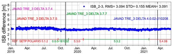
Figure 6.
The daily estimates of system-like bias between BDS-2 and BDS-3 for site SOD3 with respect to the site ABPO. During this period, the equipped receiver for SOD3 is JAVAD.
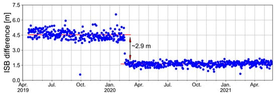
Figure 7.
The daily estimates of system-like bias between BDS-2 and BDS-3 for site LMMF with the Trimble Alloy. A noticeable jump of −2.9 m can be observed when the firmware is updated from 5.37 to 5.45.
As aforementioned, the antennae of all sites remain nearly unchanged. Hence, two stations with the same receiver type and firmware but different antennae are used to check the dependency of the bias on the antenna. For most of them, the impacts of antenna types on the bias are marginal. However, for the Trimble NetR9 with TRM59800.00 antenna, it shows clear discrepancy of up to about 1.5 m with the same receiver carrying different antennae, as shown in Figure 8, where it has been classified into two groups labeled A and B. A similar phenomenon is also reported by [5], and the reason is unclear.
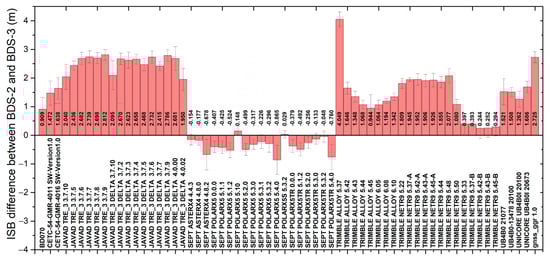
Figure 8.
The mean and STDev values for different pairs of receiver and firmware.
Finally, the mean and STDev values for each station with the same receiver and firmware are plotted in Figure 8. It can be clearly observed that different receivers have different biases, and the firmware version has a slight impact on the values, except in the Trimble Alloy 5.37, which has a relatively large bias up to 4.0 m compared with its later versions. The biases are between 2.0 m to 3.0 m for Javad receivers and within −1.0 m for Septentrio receivers. For receivers in the iGMAS network, the biases of BD070, CETC-54-GMR, UNICORE and gnss_ggr are about 1.0 m, 1.5 m, 1.5 m and 2.7 m, respectively. Clear antenna dependency is observed for the Trimble NetR9 receiver. The STDev of the estimated ISB biases between BDS-2 and BDS-3 is better than 0.2 m on average.
4.2. Impacts of Inter-System-like Bias
In this section, the impacts of the inter-system-like bias between BDS-2 and BDS-3 on the orbits and clocks are analyzed by the metrics of observation residuals, orbit boundary discontinuity, satellite laser ranging and linear clock fitting.
4.2.1. Code and Phase Residuals
Figure 9 shows the daily RMS of the code and phase residuals for solutions B1A1 and B2A1. As B1A2 and B2A2 solutions are almost the same as their counterparts B1A1 and B2A1, they are omitted for illumination. As expected, we can observe the reduction of both code and phase residuals for B2A1. Specifically, the averaged RMS of code residuals decreases from 109.1 cm to 99.8 cm, while it is reduced to 9.08 mm from 9.31 mm for phase. As theorized earlier, the mismodeling bias will be assimilated by the residuals for code and ambiguities for phase if only one ISB parameter is estimated. In addition, we can observe that the daily RMS of phase residuals increases gradually from around 8.5 mm to 9.5 mm in the selected period, where the code residuals are reduced generally. This can be attributed to the rapid increase in Septentrio receivers. Figure 10 shows the daily number of Javad, Trimble, and Septentrio receivers used in data analysis. It can be clearly observed that the number of Javad and Trimble receivers remains almost stable, while that of Septentrio receivers increases by a factor of two during the selected period. Compared to Javad and Trimble receivers, the Septentrio receiver has relatively lower code and phase residuals, as shown in Figure 11. Hence, the more the Septentrio receiver is used, lower RMS of code residuals can be obtained. It should be noted that—as seen in Figure 8—Septentrio receivers are quite different from other receivers in terms of ISB parameters estimated between BDS-2 and BDS-3. Due to the strong correlation between clock and ISB parameters, the common part of the clock error change will be absorbed by the ISB or ambiguity parameters, and the rest will be absorbed into the phase residuals. The reason for the gradual increase in phase residuals may be that in data processing, the Septentrio receivers increase gradually with time, resulting in greater inconsistency in ISB parameter estimation. The above influence will be directly projected into the phase residual sequence, resulting in a slight increase in phase residuals. Additionally, we can observe that phase residuals of B1A1 are more scattered than those of B2A1, particularly in the beginning of 2019. It is noteworthy that during this period, the number of receivers is rare, resulting in unreliable estimates of ambiguity. Once only one ISB is estimated, the mismodeling error further worsens the ambiguities. Hence, the ambiguities are prone to be fixed to the wrong values, resulting in larger phase residuals. With the increase in available stations and Septentrio receivers used, reliable estimates of ambiguities and their integer resolution can obtain stable phase residuals.
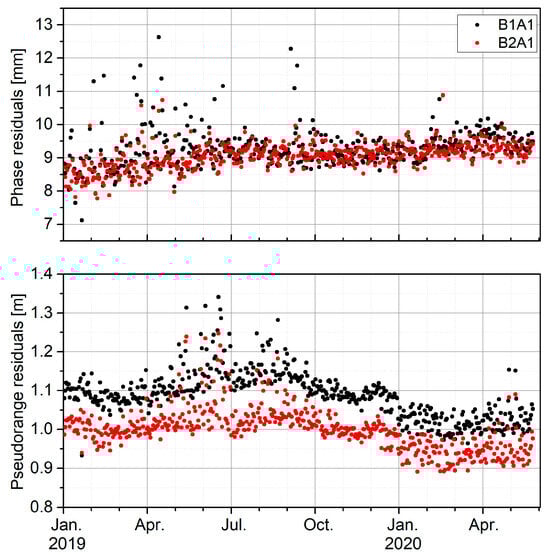
Figure 9.
The daily RMS of the code and phase residuals for B2A1 (red) and B1A1 (black) modeling the inter-system-like bias between BDS-2 and BDS-3.
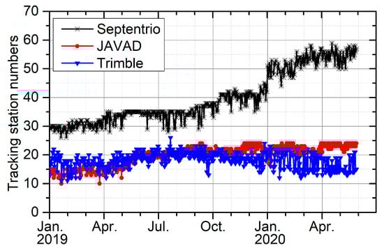
Figure 10.
The actual daily number of Septentrio, Javad and Trimble receivers used for data analysis.
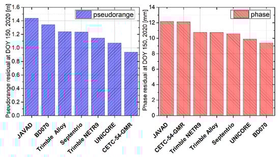
Figure 11.
The RMS of pseudorange and phase residuals at DOY 150, 2020 for seven receivers used within IGS and iGMAS networks.
4.2.2. Orbits
The effect of modeling ISB between BDS-2 and BDS-3 on precise BDS orbit determination is assessed by the metrics of orbit boundary discontinuation (OBD) and satellite laser ranging (SLR) validation. The OBD is the indicator of orbit consistency, and is the difference between two adjacent orbit solutions at the same epoch, e.g., midnight [30], while SLR is a powerful validation method for radial orbit precision.
- Orbit boundary discontinuation
As aforementioned, if the system-like bias is not properly handled, the contaminated ambiguity possibly distorts the orbit and clock estimation. To investigate these impacts, four solutions are determined. As a 24 h arc is used for data analysis, OBD varies largely if fewer tracking stations are used, particularly at the beginning of 2019. Hence, the median is employed to evaluate the three-dimensional (3D) OBD performance. Figure 12 shows the 3D OBD of BDS GEO, IGSO and MEO satellites, and the statistical results of each satellite have been listed in Table 4. For most BDS satellites, their 3D OBD is reduced when the bias is modeled. Due to the poor geometry, the 3D OBD of BDS-2 GEO is obviously worse than that of non-GEO satellites. BDS-3 IGSO satellites also show relatively poor performance due to the unmodeled non-conservative force errors and the limitation of the tracking stations, as shown in Figure 2. For the dynamic model, the solar radiation pressure should be refined to consider the perturbation from the hexagonal antenna and two smaller circle antennae [31]. It can be observed that the C41–C46 show relatively greater improvement than other BDS-3 MEO satellites for B2A1 solution. This can be attributed to more reliable ambiguity estimates and integer resolution when the system-like bias is modeled, particularly for those satellites with fewer tracking data. On the other hand, the number of receivers with Septentrio is increased gradually with time, and the ISB-like bias of the Septentrio receiver is smaller than that of Trimble and JAVAD, so less impact can be seen in the analysis. Additionally, we can observe that about a 2% improvement in ambiguity fixing rate can be obtained once the bias is modeled. The B2A2 solution is a little worse than the B2A1 solution in the precision of POD. Generally, about 6.8%, 5.9% and 1.7% improvement can be obtained for B2A1, B2A2 and B1A2 with respect to that of B1A1, and the improvement mainly appeared in the along-track. The reason may be that the radial orbit is dominated by the dynamic model, where the geometry models have more impacts on the along-track. In addition, the unmodeled ISB bias may be absorbed into clock, and the error may be mapped into orbital error in the along-track.
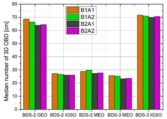
Figure 12.
The median 3D OBD of B1A1 (orange), B1A2 (green), B2A1 (black) and B2A2 (magenta) orbit solutions.
Table 4.
The median 3D OBD of B1A1, B1A2, B2A1 and B2A2 orbit solutions. Unit: mm.
- SLR validation
As an independent approach, SLR is used to evaluate the accuracy of radial orbits. Currently, C01, C08, C10, C11, and C13 from BDS-2 as well as C20, C21, C29, C30 from BDS-3 are supported in tracking by the International Laser Ranging Service (ILRS) [32]. Table 5 lists the statistical results for all the satellites of the four solutions. Here, the 3-sigma threshold is used for quality control of SLR residuals to remove the outliers. It is clearly observable that the bias in SLR residuals of C01 shifts about 13.2 cm when BDS-2 and BDS-3 are treated as two independent systems, resulting in the noticeable radial bias shifting from 12.2 cm to −1.0 cm. Due to the weak observation condition for GEO satellites, their orbit dynamic parameters are highly correlated with other parameters, i.e., ambiguity, clocks and ISBs. Hence, the improved radial orbits clearly indicate a better observation model used. However, for other non-GEO satellites, the SLR validations are almost the same, as SLR mainly reflects the precision of radial orbits, which are mainly constrained by the dynamic model.
Table 5.
SLR validation for B1A1, B1A2, B2A1 and B2A2 solutions of all BDS satellites tracked by ILRS. Unit: cm.
4.2.3. Clocks
For clock validation, the linear tread of the estimates should be removed, and the linear clock fitting (LCF) method is used [33]. For LCF, the RMS of fitting residuals is considered as an indicator to evaluate the four solutions. Table 6 lists the RMS of LCF for each satellite. In general, it can be clearly observed that the LCF RMS of BDS-2 is greater than that of BDS-3 for the GEO, IGSO, and MEO satellites, as the more stable onboard frequency standard Rubidium Atomic Frequency Standard (RAFS) and Passive Hydrogen Maser (PHM) are onboard the BDS-3. By comparison of those solutions, BDS-3 satellites show improved performance when the inter-system-like biases are considered. Generally, the average RMS of LCF is reduced from 0.050 ns to 0.038 ns and 0.082 ns to 0.069 ns for BDS-3 MEO and IGSO for B1A1 and B2A1, respectively. For BDS-3 MEO satellites, the average RMS values of LCF are 0.047 ns and 0.040 ns for B1A2 and B2A2 solutions, respectively, while for BDS-3 IGSO satellites, the results are 0.079 ns and 0.070 ns. However, BDS-2 satellites show almost identical performance for the four solutions.
Table 6.
The LCF RMS of estimated clock errors for each satellite in BDS. Unit: ns.
With regard to the time series of LCF RMS, Figure 13 is presented for the PRN C24 satellite as example. It should be noted that since the clock error series for B2A2 and B2A1 solutions are almost the same, the time series of the B2A2 solution are not shown. From Figure 13, it can be seen that the relatively large value appears at the beginning of 2019 for the solutions, as there are fewer stations available with tracking capability. Hence, the clocks are estimated unreliably. Several significant phenomena can be observed from Figure 13. After ISB is modeled correctly, the observation model and the estimated accuracy of clock error can both be improved, as shown by B1A1 (black) and B2A1 (red). For B1A1 and B1A2 (green), they both perform poorly at the beginning, which may due to fewer data. The ambiguity is easier to be fixed as wrong values. However, compared with the B1A1 solution, the B1A2 solution performs better in LCF, possibly due to better ambiguity resolution. As the number of stations increases, the results improve. As for B1A2 and B2A1 solutions, B1A2 performs worse, especially when there are fewer observation data. The ambiguity fixing is more dependent on the mathematical model in the case of scarce observations. Once ISB parameters among BDS systems are modeled correctly, a better observation model results in more accurate estimation of the clock. The fitted residuals are significantly improved after November 2019.
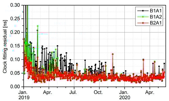
Figure 13.
The RMS of linear clock fitting for PRN C24 of B2A1 (red), B1A1 (black), and B1A2 (green) solutions.
These comparisons indicate that modeling the bias between BDS-2 and BDS-3 can improve the clock quality much more than that of orbits, as the latter are constrained by dynamic models, while the clocks are much more sensitive to the observation errors.
5. Summary and Conclusions
Following the previous discovery of [9], we further investigate the characteristics of the system-like biases between BDS-2 and BDS-3 and their dependency on the receiver, firmware, antenna, and other factors in this contribution. In this paper, the data during DOY 1, 2019 to 150, 2021 from the IGS and iGMAS network were used, and we clearly observe that the number of tracking stations varies with time and satellite. In general, the satellites with PRN beyond 37 have relatively fewer tracking data, but this quantity increases with updates of receivers. Although the biases for IF combination of B1I and B3I signals are estimated, they mainly come from the inconsistency in B1I signals of BDS-2 and BDS-3. The satellite-specific ISBs are estimated, and an obvious discrepancy between satellites as well as BDS-2 and BDS-3 can be identified. For most of the stations, the daily estimates of the biases are quite stable, with STDev less than 0.2 m. Strong dependency on the receiver type can be identified, but the firmware and antenna have impacts on them. In addition, clear annual variations are identified for the stations ABPO and MIZU. In addition, we have analyzed the effect of the ISB difference between BDS-2 and BDS-3 on the IF combination ambiguity fixing. The integer properties of the double-difference MW combination are contaminated, and the influence has been derived.
Furthermore, we have investigated their impacts on the orbit and clock solutions. By modeling the inter-system-like bias without considering the influence on BDS ambiguity fixing of inter-constellations, the residuals of code and phase measurements are reduced by around 9.3 cm and 0.23 mm, respectively. A slight increase (about 2%) in ambiguity fixing rate can be obtained, resulting in a 6.8% improvement in 3D orbit consistency shown by OBD. With SLR validation, the SLR residual of C01 shifts 13.2 cm, which has marginal impacts on other satellites. However, the clocks obtain many more benefits than orbits, as the latter are constrained by dynamic models. The RMS of linear clock fitting is reduced from 0.050 ns to 0.038 ns for BDS-3 MEO satellites. Hence, the biases need to be considered for combined BDS-2 and BDS-3 data analysis, especially when rare observation data can be gained.
Author Contributions
Conceptualization, X.X.; methodology, X.X.; software, X.X.; validation, Z.C.; formal analysis, X.X.; investigation, Z.C.; data curation, X.X.; writing—original draft preparation, X.X.; writing—review and editing, Z.C.; visualization, X.X.; supervision, Z.C.; project administration, X.X.; funding acquisition, X.X. and Z.C. All authors have read and agreed to the published version of the manuscript.
Funding
This research was funded by the National Natural Science Foundation of China (42304032), the Fundamental Research Funds for the Central Universities (2042021kf0065), the China Postdoctoral Science Foundation (2020M682483), the Education Commission of Hubei Province of China (Q20202801), and the PhD Research Startup Foundation of Hubei University of Science and Technology (L07903/170428).
Data Availability Statement
The GNSS data from IGS network used in the paper are freely accessible and can be downloaded via the ftp or the websites https://cddis.nasa.gov/archive/pub/gps/data/daily (accessed on 1 November 2023), ftp://igs.igr.fn/pub/igs/data (accessed on 1 November 2023), and ftp://igs.gnsswhu.cn/pub/gps/data/daily (accessed on 1 November 2023). The iGMAS data can be obtained through application on the website http://www.igmas.org (accessed on 1 November 2023).
Acknowledgments
The IGS, iGMAS, and ILRS are gratefully acknowledged for providing the multi-GNSS and SLR tracking data.
Conflicts of Interest
The authors declare no conflict of interest.
References
- Yang, Y.; Tang, J.; Montenbruck, O. Chinese Navigation Satellite Systems. In Springer Handbook of Global Navigation Satellite Systems; Teunissen, P.J., Montenbruck, O., Eds.; Springer: Cham, Switzerland, 2017. [Google Scholar]
- Yang, Y.; Ding, Q.; Gao, W.; Li, J.; Xu, Y.; Sun, B. Principle and performance of BDSBAS and PPP-B2b of BDS-3. Satell. Navig. 2022, 3, 5. [Google Scholar] [CrossRef]
- Wanninger, L.; Beer, S. BeiDou satellite-induced code pseudorange variations: Diagnosis and therapy. GPS Solut. 2015, 19, 639–648. [Google Scholar] [CrossRef]
- Zhou, R.; Hu, Z.; Zhao, Q.; Li, P.; Wang, W.; He, C.; Cai, C.; Pan, Z. Elevation-dependent pseudorange variation characteristics analysis for the new-generation BeiDou satellite navigation system. GPS Solut. 2018, 22, 60. [Google Scholar] [CrossRef]
- Gong, X.P.; Lou, Y.D.; Zheng, F.; Gu, S.F.; Shi, C.; Liu, J.N.; Jing, G.F. Evaluation and calibration of BeiDou receiver-related pseudorange biases. GPS Solut. 2018, 22, 98. [Google Scholar] [CrossRef]
- Zheng, F.; Gong, X.; Lou, Y.; Gu, S.; Jing, G.; Shi, C. Calibration of BeiDou Triple-Frequency Receiver-Related Pseudorange Biases and Their Application in BDS Precise Positioning and Ambiguity Resolution. Sensors 2019, 19, 3500. [Google Scholar] [CrossRef] [PubMed]
- Zhang, Y.; Kubo, N.; Chen, J.; Wang, A. Calibration and analysis of BDS receiver-dependent code biases. J. Geod. 2021, 95, 43. [Google Scholar] [CrossRef]
- Li, X.X.; Xie, W.L.; Huang, J.X.; Ma, T.Z.; Zhang, X.H.; Yuan, Y.Q. Estimation and analysis of differential code biases for BDS3/BDS2 using iGMAS and MGEX observations. J. Geod. 2019, 93, 419–435. [Google Scholar] [CrossRef]
- Mi, X.; Sheng, C.; El-Mowafy, A.; Zhang, B. Characteristics of receiver-related biases between BDS-3 and BDS-2 for five frequencies including inter-system biases, differential code biases, and differential phase biases. GPS Solut. 2021, 25, 113. [Google Scholar] [CrossRef]
- Song, Z.; Chen, J.; Wang, B.; Yu, C. Analysis and Modeling of the Inter-System Bias Between BDS-2 and BDS-3. In China Satellite Navigation Conference (CSNC) 2020 Proceedings: Volume II, Singapore, 2020; Sun, J., Yang, C., Xie, J., Eds.; Springer Nature: Singapore, 2020; pp. 279–289. [Google Scholar]
- Pan, L.; Zhang, Z.; Yu, W.; Dai, W. Intersystem Bias in GPS, GLONASS, Galileo, BDS-3, and BDS-2 Integrated SPP: Characteristics and Performance Enhancement as a Priori Constraints. Remote Sens. 2021, 13, 4650. [Google Scholar] [CrossRef]
- Zhao, W.; Chen, H.; Gao, Y.; Jiang, W.; Liu, X. Evaluation of Inter-System Bias between BDS-2 and BDS-3 Satellites and Its Impact on Precise Point Positioning. Remote Sens. 2020, 12, 2185. [Google Scholar] [CrossRef]
- Mi, X.; Zhang, B.; Yuan, Y.; Luo, X. Characteristics of GPS, BDS2, BDS3 and Galileo inter-system biases and their influence on RTK positioning. Meas. Sci. Technol. 2019, 31, 015009. [Google Scholar] [CrossRef]
- Jiao, G.; Song, S.; Chen, Q.; Huang, C.; Su, K.; Wang, Z.; Cheng, N. Modeling and Analysis of BDS-2 and BDS-3 Combined Precise Time and Frequency Transfer Considering Stochastic Models of Inter-System Bias. Remote Sens. 2021, 13, 793. [Google Scholar] [CrossRef]
- Zhang, F.; Liu, C.; Xiao, G.; Zhang, X.; Feng, X. Estimating and Analyzing Long-Term Multi-GNSS Inter-System Bias Based on Uncombined PPP. Sensors 2020, 20, 1499. [Google Scholar] [CrossRef] [PubMed]
- Li, R.; Li, Z.; Wang, N.; Tang, C.; Ma, H.; Zhang, Y.; Wang, Z.; Wu, J. Considering inter-receiver pseudorange biases for BDS-2 precise orbit determination. Measurement 2021, 177, 109251. [Google Scholar] [CrossRef]
- Steigenberger, P.; Montenbruck, O. Multi-GNSS Working Group. In International GNSS Service Technical Report 2019 (IGS Annual Report); IGS Central Bureau and University of Bern, Bern Open Publishing: Bern, Switzerland, 2019. [Google Scholar]
- Mi, X.L.; Zhang, B.C.; Odolinski, R.; Yuan, Y.B. On the temperature sensitivity of multi-GNSS intra- and inter-system biases and the impact on RTK positioning. GPS Solut. 2020, 24, 112. [Google Scholar] [CrossRef]
- Hatch, R. The synergism of GPS code and carrier measurements. In International Geodetic Symposium on Satellite Doppler Positioning; Physical Sciences Laboratory of New Mexico State University: Las Cruces, NM, USA, 1982; Volume 2, pp. 1213–1231. [Google Scholar]
- Melbourne, W.G. The case for ranging in GPS-based geodetic systems. In Proceedings of the First International Symposium on Precise Positioning with the Global Positioning System, Rockville, MD, USA, 15–19 April 1985; pp. 373–386. [Google Scholar]
- Wübbena, G. Software developments for geodetic positioning with GPS using TI-4100 code and carrier measurements. In Proceedings of the First International Symposium on Precise Positioning with the Global Positioning System, Rockvile, MD, USA, 15–19 April 1985; pp. 403–412. [Google Scholar]
- Peng, Y.; Dai, X.; Lou, Y.; Gong, X.; Zheng, F. BDS-2 and BDS-3 combined precise orbit determination with hybrid ambiguity resolution. Measurement 2022, 188, 110593. [Google Scholar] [CrossRef]
- Ge, M.; Gendt, G.; Dick, G.; Zhang, F.P.; Rothacher, M. A new data processing strategy for huge GNSS global networks. J. Geod. 2006, 80, 199–203. [Google Scholar] [CrossRef]
- Wang, C.; Guo, J.; Zhao, Q.L.; Liu, J.N. Yaw attitude modeling for BeiDou I06 and BeiDou-3 satellites. GPS Solut. 2018, 22, 117. [Google Scholar] [CrossRef]
- Lin, X.; Bin, B.; Liu, Y.; Xiong, S.; Bai, T. Satellite geometry and attitude mode of MEO satellites of BDS-3 developed by SECM. In Proceedings of the ION GNSS 2018, Institute of Navigation, Miami, FL, USA, 24–28 September 2018; pp. 1268–1289. [Google Scholar]
- Petit, G.; Luzum, B. IERS Conventions (2010) (IERS Technical Note; 36) Frankfurt am Main: Verlag des Bundesamts für Kartographie und Geodäsie; IERS: Frankfurt, Germany, 2010. [Google Scholar]
- Wang, C.; Guo, J.; Zhao, Q.L.; Liu, J.N. Empirically derived model of solar radiation pressure for BeiDou GEO satellites. J. Geod. 2019, 93, 791–807. [Google Scholar] [CrossRef]
- Rodriguez-Solano, C.J.; Hugentobler, U.; Steigenberger, P. Impact of Albedo Radiation on GPS Satellites. Iag. Symp. 2012, 136, 113–119. [Google Scholar]
- Gong, X.; Zheng, F.; Gu, S.; Zhang, Z.; Lou, Y. The long-term characteristics of GNSS signal distortion biases and their empirical corrections. GPS Solut. 2022, 26, 52. [Google Scholar] [CrossRef]
- Griffiths, J.; Ray, J.R. On the precision and accuracy of IGS orbits. J. Geod. 2009, 83, 277–287. [Google Scholar] [CrossRef]
- Chen, Z.; Wu, X. General design of the third generation BeiDou Navigation Satellite System. J. Nanjing Univ. Aeronaut. Astronaut. 2020, 52, 835–845. (In Chinese) [Google Scholar]
- Pearlman, M.R.; Degnan, J.J.; Bosworth, J.M. The International Laser Ranging Service. Adv. Space Res. 2002, 30, 135–143. [Google Scholar] [CrossRef]
- Montenbruck, O.; Hugentobler, U.; Dach, R.; Steigenberger, P.; Hauschild, A. Apparent clock variations of the Block IIF-1 (SVN62) GPS satellite. GPS Solut. 2012, 16, 303–313. [Google Scholar] [CrossRef]
Disclaimer/Publisher’s Note: The statements, opinions and data contained in all publications are solely those of the individual author(s) and contributor(s) and not of MDPI and/or the editor(s). MDPI and/or the editor(s) disclaim responsibility for any injury to people or property resulting from any ideas, methods, instructions or products referred to in the content. |
© 2023 by the authors. Licensee MDPI, Basel, Switzerland. This article is an open access article distributed under the terms and conditions of the Creative Commons Attribution (CC BY) license (https://creativecommons.org/licenses/by/4.0/).