Abstract
CubeSats have extensive applications in the realm of remote sensing. However, due to size constraints, attitude determination and control systems (ADCS) often adopt an integrated and densely packed structure. This leads to simple interference in the magnetic field measurements from components like reaction wheels and magnetorquers, resulting in magnetometer failures. Furthermore, the magnetic interference compromises the ability to dump the angular momentum of CubeSats. This leads to attitude control and remote sensing mission failures. To address these challenges, we introduce a dynamics-sensing, magnetic, fault-tolerant attitude control method that achieves attitude control without a priori magnetic field information generated from a magnetometer, restoring the remote sensing capabilities of CubeSats under magnetic failure. The proposed geomagnetic field sensing method, based on the temporal expansion geomagnetic vector calculate algorithm (GVCA), decouples the observation equations in three axes through control segmentation in the time domain to address the singularity issue of the Kalman coefficient matrix. Additionally, the magnetic field vector can be obtained in real time with acceptable computational consumption. Moreover, utilizing this real-time magnetic field information, the fault-tolerant control strategies and multi-mode control laws can progressively restore destabilized CubeSats to their regular states without performance degradation. We conducted numerical simulation experiments to evaluate the effectiveness of our method and system. Beyond the numerical simulations, we also built hardware systems. We designed and implemented a plug-and-play (PnP) ADCS to apply our methodology, further supporting CubeSats’ high-precision remote sensing. Furthermore, with the aid of a space environment simulation platform, we verified the performance of our system and method under conditions simulating the actual space environment. Ground testing demonstrated that our proposed method was able to identify the magnetic field and achieve high-performance attitude control with magnetic field measurement failures. The system’s pointing accuracy was better than 0.02 degrees, and the attitude stability surpassed 0.003 degrees per second.
1. Introduction
Over the years, CubeSats have gradually taken on more remote sensing tasks. Compared to traditional satellites, they are more advantageous in terms of cost [1,2], mission duration [3], and constellation deployment [4,5,6]. The extensive applications of CubeSats include Earth observation [7], disaster detection and monitoring [8,9,10], oceanic surveillance [11], and atmospheric research [12]. With CubeSats becoming increasingly crucial in remote sensing, it is imperative to delve deeper into the systems that ensure their functionality.
The integrated attitude determination and control system (iADCS) plays a critical role in CubeSats attitude control; its reliability and performance directly impact the quality of remote sensing missions [13,14,15,16]. The iADCS possesses the capability to ascertain the magnetic field data of the satellite, thus laying a solid foundation for the control methodologies. Precise magnetic field measurements are the essential ingredient for reliable attitude control. Nevertheless, in space, CubeSats are subjected to a variety of disturbances that can potentially compromise their geomagnetic measurement functionality [17]. CubeSats are confronted with issues such as magnetic disturbances from residual magnetism and coil equipment in the induction motor, as well as instrument aging and damage [18]. Especially for the iADCS of the CubeSats [19,20], the magnetic field sensor is compactly mounted with other components, such as the reaction wheels and the magnetorquers, due to demanding volume constraints, resulting in geomagnetic measurements that are extremely susceptible to disturbances. Moreover, the measuring sensors might malfunction due to the use of commercial off-the-shelf (COTS) devices. An iADCS with high magnetic robustness is, thus, essential for accurate attitude determination and control considering these multifaceted disturbances and failure possibilities, ensuring remote sensing CubeSats’ operational performance and mission longevity despite the inherent challenges.
The CubeSats with fault-tolerant control (FTC) bring tangible benefits, such as heightened mission resilience and significant risk reduction [21,22]. Magnetic field sensing of magnetic FTC is fundamental to mitigating these challenges. Magnetic disturbances, particularly those stemming from residual magnetism and induction coils, pose unique challenges due to their inherent and irremediable nature [23]. In recent years, numerous researchers have been investigating various approaches and techniques to address this issue, aiming to eliminate internal and external interferences and attain highly dependable magnetic field measurements. These endeavors have played a pivotal role in advancing the construction of magnetic, fault-tolerant control systems.
In accordance with Biot-Savart’s law, it is established that magnetic field intensity varies inversely with distance. Consequently, a conventional approach involves increasing the separation distance between magnetic field sensors and potential sources of interference, such as magnetic torquers and reaction wheels, in order to mitigate the influence of interfering magnetic fields [24,25]. However, this method is not suitable for the iADCS of CubeSats due to the stringent size constraints and high spatial density. In addition to the traditional approach of increasing spatial separation, interference compensation can also be achieved through on-orbit correction methods.
To avoid the impact of residual magnetism and unknown orbital magnetic disturbances, Broadfoot et al. proposed a vector periodic correction method for calibrating magnetometers on the Swarm-Echo spacecraft. Their findings indicate the efficacy of this approach in rectifying magnetic field interference [26]. While magnetometer calibration can be accomplished through various methods [27], it is worth noting that the magnetic field interference generated by reaction wheels is highly dynamic and unavoidable. Consequently, some scholars have endeavored to mitigate this interference through time-domain-based techniques.
Xing YT has introduced a distributed model predictive control scheme. The proposed methodology entails the periodic updating of the reaction wheels and magnetorquers at distinct sampling intervals, thereby facilitating a swifter response to disturbances within the system. Additionally, it incorporates a temporal domain consideration regarding the switching of magnetic torquers to mitigate interference on the satellite’s magnetometers [28]. Nevertheless, in the temporal sequence, a reduction in the attitude determination and control system (ADCS) control performance during certain intervals is inevitable. Instead of focusing on physical space, researchers propose the efficacy of isolation in other domains, with a specific emphasis on the frequency domain.
DM Miles et al. addressed the issue of magnetic disturbances associated with the magnetometer on the Cassiope spacecraft. They employed a frequency-domain approach, integrating data from multiple sensors and spatial dimensions to investigate the characteristics of reaction wheels across various harmonic frequencies. Their study introduced a real-time calibration method aiming to compensate for the magnetic interference stemming from reaction wheels, successfully resolving the magnetic interference issue on the Cassiope spacecraft [29]. Matthew G. Finley et al. applied a multi-channel singular spectrum analysis technique to simultaneously decompose multiple time series, effectively mitigating the magnetic field interference generated by reaction wheels. Their approach significantly reduced the local interference caused by reaction wheels, decreasing it from 1.90 nT RMS to 0.21 nT RMS, achieving a remarkable reduction of up to 89.0% [30,31]. However, this method has its limitations; it is difficult to effectively separate the signal component from the interference component when the signal components overlap in both time and frequency with the interfering components. Furthermore, the computational consumption associated with this approach may be prohibitive, posing challenges in terms of meeting the computational requirements of on-board computers. In addition to eliminating the influence of interference sources, an alternative and viable approach involves fault monitoring and isolation through redundant configurations.
Andrea Colagrossi and Michèle Lavagna have made a contribution to this field by designing and implementing an FTC and orbit determination system (AODS) specifically tailored for small satellite platforms [32]. This discourse underscores the importance of integrating abundant sensors and actuators into satellites, thus enhancing their functionality and versatility. This innovative AODS system is equipped with embedded failure detection and isolation features, possessing the crucial capability for autonomous management and component reconfiguration to recover from basic failures. This pioneering work has significantly bolstered the robustness of satellite systems. However, it is worth noting that the integration of numerous sensors and actuators introduces additional cost and weight considerations for the satellite, which is not suitable for the iADCS of remote sensing CubeSats with demanding size requirements.
In the context of the research under discussion in this section, a multitude of scholars have conducted comprehensive research on the mitigation of magnetic field interference and the achievement of highly reliable magnetic field measurement and control. These research approaches encompass strategies such as increasing the spatial separation between magnetic field sensors and sources of interference [24,25]; the calibration and correction of disturbed magnetic field sensors [26,27]; partitioning the operation of coils and magnetometers in a time sequence [28]; employing digital signal processing techniques in the frequency domain to filter out magnetic field interference [29,30,31]; and the development of redundant fault-tolerant control systems [32]. Nevertheless, calibration and corrections cannot eliminate the effects of highly dynamic magnetic disturbances generated by reaction wheels. Temporal decomposition methods tend to incur degradation in control performance. Filtering through signal processing techniques cannot effectively separate overlapping interferences, and may impose an undue computational burden on on-board computers. Traditional approaches based on spatial isolation and redundant fault-tolerant control systems prove inadequate to meet the requirements of compact and integrated iADCS systems.
In the realm of the existing research, all studies involve magnetometer-dependent methodologies, necessitating the acquisition of essential magnetic field data via magnetometer sensors. These investigations endeavor to achieve precise geomagnetic field vectors by either isolating or suppressing disruptive influences. Nevertheless, the inherent limitations of these methodologies render them unsuitable for integration within the iADCS of remote sensing CubeSats. In response to this challenge, we introduce an innovative dynamics-sensing, magnetic, fault-tolerant control method by decoupling the correlation between the magnetic disturbance link and the spatial magnetic field vector. This approach entirely divorces itself from reliance on magnetometer sensors, thereby circumventing the predicaments typically associated with magnetometer-dependent methodologies. It effectively addresses the challenges posed by magnetic interference, a common contributor to iADCS failures, thus ensuring the successful execution of remote sensing missions using CubeSats.
As shown in Figure 1, by merging Euler’s dynamic equations with Kalman filtering, we initially crafted magnetic field identification and prediction equations. By employing temporal control decomposition, we decoupled the observation equations across three axes, addressing singularity concerns in the Kalman coefficient matrix. This birthed the time-domain-extended geomagnetic vector calculation algorithm (GVCA), which promises real-time magnetic field sensing with low computational overhead. Furthermore, by leveraging real-time magnetic field vectors and aligning them with the demands of remote sensing CubeSats space missions, we propose a multi-modal FTC strategy and methodology. This ensures the stabilization of CubeSats under failure-induced instability without compromising the performance. In culmination, to implement the suggested techniques and support remote sensing CubeSats, we developed a plug-and-play attitude measurement and control system (PnP ADCS) tailored for remote sensing CubeSats, ensuring seamless integration with target CubeSats. The efficacy of the algorithms and systems was ascertained through rigorous numerical simulations, encompassing practical engineering challenges like noise, disturbances, and constraints. To objectively evaluate the performances of our methodologies and systems, we established an experimental platform with a comprehensive ground-based space environment simulation integrating space dynamics, stellar optics, and spatial magnetic fields. Operating under near-authentic on-orbit conditions, this platform enabled a precise performance assessment. Ground experiments substantiated that our proposed methodologies and systems can deliver high-performance attitude control, even under magnetic field measurement failure.
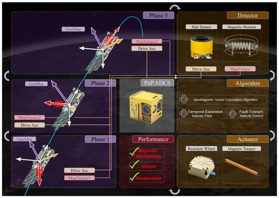
Figure 1.
The proposed control methodology framework.
The primary contributions of this paper are delineated as follows: (1) We present an inventive dynamics-sensing magnetic fault-tolerant control methodology without magnetic field sensors, distinct from conventional magnetometer-dependent methods. This methodology mitigates issues related to spatial constraint conflicts, computational burden, and performance degradation, offering a viable solution to the magnetic interference challenges encountered in the iADCS of remote sensing CubeSats. It thereby secures the successful execution of remote sensing missions using CubeSats. (2) We introduce a temporal expansion geomagnetic vector calculation algorithm. The algorithm decouples the observation equations in three axes through control segmentation in the time domain to address the singularity issue of the Kalman coefficient matrix, and enables the real-time acquisition of magnetic field vectors with low computational consumption. (3) We implement a fault-tolerant control strategy based on real-time magnetic field vectors in conjunction with multi-mode control laws, ensuring high control performance. Additionally, in support of CubeSats in remote sensing applications, we developed a PnP ADCS and a comprehensive ground-based space environment simulation experimental system, thereby advancing the practical utilization of CubeSats in remote sensing endeavors.
2. Brief Introduction of Magnetic Fault-Tolerant Attitude Control
The structure of the dynamics-sensing magnetic fault-tolerant attitude control methodology is illustrated in Figure 2. This method primarily encompasses the magnetic sensing loop and the attitude control loop, both integrated into the PnP ADCS designed for remote sensing CubeSats.
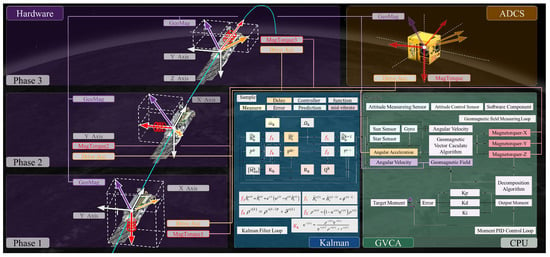
Figure 2.
The architecture of the magnetic tolerance system and its associated control algorithm.
The magnetic sensing loop and the attitude control loop exhibit mutual coupling. The control torque, derived from the attitude control output, serves as the input for the magnetic sensing loop. Together with the information on CubeSats’ attitude sensors, they constitute the sampled data required for sensing the magnetic field vector. The magnetic field vector obtained through the magnetic sensing loop serves as crucial measurement information for the attitude control loop, and is employed for the purpose of calculating the control torque vector.
Specifically, the attitude control actuators generate control torques, providing dynamic excitation for magnetic field sensing. Given the prerequisite availability of attitude information and excitation sample data, the magnetic field vector information is implied in the dynamic equation. However, due to the three-axis coupling between dynamics and magnetic moments, as well as the influence of noise and errors, direct estimation of the magnetic field vector is infeasible. Therefore, it becomes imperative to combine the attitude control loop with Kalman filtering techniques, decomposing the control magnetic moment in the time domain to achieve a three-axis decoupled observation equation. This process also addresses the singularity issues related to the Kalman coefficient matrix, ultimately allowing for accurate perception of the magnetic field vector.
Furthermore, based on the real-time perception of the magnetic field vector and in conjunction with remote sensing CubeSats’ on-orbit tasks, a fault-tolerant control strategy as well as multi-mode attitude control laws are employed to generate control torques sent to the actuators. These torques are used to adjust CubeSats to the desired attitude, thus supporting the successful completion of remote sensing missions. It is essential to note that the coupling between the magnetic sensing loop and the attitude control loop requires the extension of the control torques in the time domain to meet the decoupling requirements of dynamics sensing.
3. Methodology of the Algorithm and Hardware
3.1. Geomagnetic Vector Calculation Algorithm (GVCA)
In the attitude control area, three coordinate systems were used to describe the dynamic and kinematic vectors. As shown in Figure 3, in the inertial Cartesian coordinate system , whose origin is located at the center of the Earth, the z-axis is perpendicular to the equatorial plane, the x-axis points in the direction of the vernal equinox, and the y-axis is determined by the definition of the Cartesian coordinate system. The body Cartesian coordinate system , whose origin is located at the center of mass of the spacecraft, has the , , and axes solidly connected with the spacecraft, and these represent the roll, pitch, and yaw axes, respectively. The orbital Cartesian coordinate system has its origin at the center of mass of the spacecraft, and the z-axis points to the center of the Earth; the x-axis is perpendicular to the z-axis in the orbital plane, and the y-axis is in the same direction as the negative normal to the orbital plane. Let the angular velocity vector of with respect to be denoted as . The component vector of in frame is represented as . For CubeSats, which can be approximated as rigid bodies, their Euler dynamical equations can be described as:
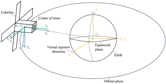
Figure 3.
The definitions of the three coordinate systems; yellow frame: the inertial Cartesian coordinate system; green frame: the body Cartesian coordinate system; blue frame: the orbital Cartesian coordinate system.
In Equation (1), denotes the moment of momentum of all reaction wheels with respect to each spindle expressed in . is the control torque generated by the reaction wheels and magnetorquers. is the disturbance moment and the unmodeled disturbances. is the inertia matrix of CubeSats, expressed in , which takes the following form: . Due to the disturbance torque in outer space being substantially lower than the other values in the dynamics equation, Equation (1) within this section can be restated as the following differential equation.
where is the control torque generated by the reaction wheels. The magnetic control torque is expressed as , while is the geomagnetic vector expressed in , and is the magnetic dipole moment generated by the magnetorquers.
The expression of the discrete-time controlled process is displayed below (Equation (3)).
where represents the times sampling, while indicates the time interval between the k-th and the (k − 1)-th sampling: , .
For convenience of expression, Equation (3) can be expressed as follows.
By rearranging Equation (4), the geomagnetic field can be expressed in terms of the output magnetic moment and moment, as shown in Equation (5).
However, directly solving from Equation (5) does not yield effective geomagnetic field information, as noise can mask meaningful excitation. Moreover, storing an excessive amount of sampled data for the least-squares solution leads to prohibitive computational costs, rendering it infeasible in practical applications. Additionally, given the properties of , is a singular matrix, meaning that Equation (5) cannot be solved directly.
To address the issues of system noise and computational cost, we integrate the dynamics equation with Kalman filtering. We define the state-space vector as the component of the geomagnetic field vector in the body frame . The observation equation of the system can be obtained from Equation (4), expressed as follows. The term represents the measurement noise.
The time derivative of the geomagnetic vector with respect to the inertial frame is denoted as . Furthermore, the time derivative of the geomagnetic vector with respect to the body frame is represented as . Thus, we have Equation (7):
When transforming Equation (7) into the body frame, we obtain the following expression.
In light of Earth’s magnetic field being dipolar, Gauss’s law of magnetism works. Furthermore, owing to the rotationally symmetric nature of Earth’s magnetic field, aligned along the axis formed by the North and South Poles, a satellite circumnavigating the Earth along a nearly circular orbit experiences a rate of change in the direction of the geomagnetic field that does not exceed its argument of perigee angular velocity . Meanwhile leads to , so Equation (9) is obtained:
By discretizing Equation (9), the following expression can be derived:
Within the confines of this discourse, represents the unit matrix of the subscript order: .
From Equation (10), the state equation of the system can be expressed as
where , while signifies the process noise.
By combining Equations (6) and (11), the iterative equation set for magnetic field sensing can be derived as:
In this context, is the k-th optimal estimate of the body-fixed component of the geomagnetic field vector, and symbolizes the value of the geomagnetic vector’s body component , predicted times. represents a 3 × 3 Kalman gain matrix, signifies the a priori covariance matrix, and is utilized to update the a priori covariance matrix. denotes the covariance matrix corresponding to system measurement noise , while is the covariance matrix associated with process noise .
By employing Equation (12) for on-orbit magnetic field sensing, issues related to noise and computational cost can be mitigated. However, the dilemma of singular matrices still persists. It is discernible from the system observation in Equation (6) that presents a scenario of three-axis coupling. Since the rank of the coefficient matrix is less than three, its corresponding state space vector derived from the sensor measurement values is infinitely numerous. This condition leads to singularity in the inverse matrix during the solution process of the Kalman coefficient matrix, causing a failure in the solution. Simultaneously, due to the two-dimensional nature of the magnetic moment, it is unable to provide effective continuous magnetic moment output throughout the process. The Kalman coefficient matrix of the system observation equation possesses a zero-matrix situation, leading to an invalid observation equation.
In summary, this study integrates the perception and control methods. By splitting the control magnetic moment in the time domain, we provide three-axis decoupled control magnetic moments in a time-division multiplexed manner. Simultaneously, by considering a mode where prediction is only valid under an ineffective observation equation, we decoupled the system’s observation equation across three axes. This effectively addressed the singularity issue of the Kalman coefficient matrix, achieving multi-segment decoupled identification for three-axis magnetic fields.
As shown in Figure 4, the coupled identification and control method decoupled the target control magnetic moment into three. We define the provision of three control magnetic moments, , , and , as one complete perception-control cycle. For the first control in a single perception-control cycle, the system observation Equation (6) can be transformed into:
where .
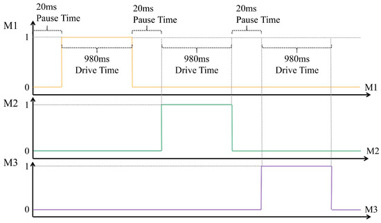
Figure 4.
The time sequential logic of the geomagnetic vector calculation algorithm (GVCA) magnetorquer’s output.
Simplifying Equation (13), the system’s observation equation can be expressed as:
From Equation (14), it is evident that the system’s observation equation was decoupled into three axes. For sensing and , their Kalman gains were and, respectively. However, for , the Kalman gain was 0, implying that can only be predicted through the state equation, Equation (11). The derivations for the other two controls are analogous. Thus, each magnetic control can excite the magnetic field in two axes, while the other axis is updated only through prediction.
The decoupled one-dimensional iterative equation for sensing the magnetic field in the x-axis can be expressed as:
where represents the k-th optimal estimate of the x-axis component of the geomagnetic field vector in the body frame; represents the k-th predicted value of the x-axis component of the geomagnetic field vector in the body frame; and is the corresponding measurement value from the observation equation. Based on the input control’s magnetic moment, it can be determined using the following equation:
The input, , can be derived from Equation (11).
The coefficient , representing the Kalman gain, can be derived from the subsequent equation:
is the 1 × 1 Kalman gain.
In Equation (19), represents the covariance corresponding to the system measurement noise; is the a priori covariance; and can be obtained through the following equation:
The priori covariance is updated by , and is the covariance corresponding to the process noise .
Referring to Equation (15), the decoupled one-dimensional iterative equations for the other two magnetic field axes can be derived. With this, we successfully established the time-domain extended GVCA method for magnetic field sensing.
3.2. Fault-Tolerant Control Strategy and Control Law
Based on magnetic field information acquired in real time and the on-orbit task requirements of the CubeSats remote sensing satellite, we proposed a reliable multi-mode fault-tolerant control strategy to address the instability of CubeSats caused by magnetic faults. The instability of CubeSats due to magnetic failures is often observed during the angular momentum unloading phase. Because of the magnetic fault, the satellite’s angular momentum cannot be unloaded normally, leading to a gradual increase in its rotational angular velocity, eventually entering an uncontrollable, unstable state.
Therefore, the primary control mode is the despin mode. During this phase, the angular momentum of the ADCS’s reaction wheel is entirely transferred to the satellite. The execution mechanism providing the control torque is the magnetorquers. The magnetic field required for magnetic control can be acquired in real time through the GVCA, and the magnetic moment produced by the magnetorquers will excite the GVCA for magnetic field iteration. The control law for the despin phase is as follows:
In Equation (21), represents the component vector of the despinning control torque in the body frame . is the control parameter for the despinning mode. The definitions of and the definitions of and are similar to and . represents the control error for the despinning mode, while denotes the rate of change of the control error over time. The last term, , represents the decoupling term for the three-axis control under magnetic control only, which is obtained based on the Euler dynamical Equation (1).
During the despinning phase, CubeSats gradually enter a stable state, and the ADCS establishes a basic controlled attitude. Prolonged instability leads the satellite’s energy resources into a deficient state. At this point, the ADCS transitions into sun-pointing mode to replenish energy. We propose the sun-pointing mode control law based on Euler’s axis angle as follows:
In Equation (22), represents the component vector of the sun-pointing control torque in the body frame . and are the control parameter matrices for the sun-pointing mode. denotes the target angular velocity for the sun-pointing mode. The last term represents the decoupling term for the three-axis control using reaction wheels, which is obtained based on the Euler dynamical Equation (1). represents the error for the sun-pointing mode, which is computed as follows:
In the described system, represents the transformation function that converts quaternions to Euler angles. The vector delineates the sun’s direction to the satellite, expressed in the satellite’s body frame . The z-axis vector of the body frame , expressed in , is defined as . From the geometric relationship between and , the attitude expressed in terms of the axis-angle representation can be obtained as follows: The axis is ; can be obtained by normalizing ; and the angle is . Then, the quaternions and Equation (23) can be obtained from the axis-angle representations and . Concurrently, during this phase, the momentum from the flywheel is being unloaded. The torque in this unloading phase is driven by the magnetic moment.
Once the satellite has replenished its energy reserves, it transitions from a sun-pointing (heliocentric) mode to an Earth-stable mode. This transition ensures that the satellite maintains its attitude for prolonged orbital operations, facilitating the execution of its remote sensing objectives. The proposed control law for the Earth-stable mode employs error-quaternions to regulate attitude. Error-quaternions effectively encapsulate the deviation between the satellite’s actual and desired attitudes. Leveraging these error-quaternions allows for a robust and precise attitude control mechanism, ensuring optimal alignment with the mission requirements.
In the body framework , is the column vector representing control torque components within the body frame for the Earth-stable mode. The matrices and are the control parameters for this mode. The term represents the attitude error for Earth-stable positioning, while denotes its first derivative or rate of change. is a compensatory term for orbital angular velocity, with being the scalar representation of this orbital angular velocity. The computation for is formulated as follows:
Furthermore, symbolizes the satellite’s attitude in quaternion representation relative to its orbital frame. The target attitude in the same frame is depicted by , while serves as an auxiliary quaternion term. These quaternions essentially offer a compact, non-singular way to describe the satellite’s orientation and desired orientation with respect to its orbit, providing critical information for the attitude control system.
It is worth noting that the magnetic field information in the state of ADCS magnetic failure is provided in real time by the GVCA. It is crucial to emphasize that the body system’s magnetic field intensity in the subsequent control laws are all real-time online identification results. Furthermore, the magnetic moments are generated in a time-divided and segmented manner according to the time domain expansion requirements of the GVCA.
3.3. Structure of ADCS
To substantiate the efficacy of the GVCA, an experimental platform encompassing the ADCS and the verification algorithm was developed. This section offers a detailed account of the design elements of both the ADCS and the experimental platform.
The ADCS, featuring the GVCA, is depicted in the following diagram, and all components come from Tsinghua/TY-Space Corporation.
The PnP ADCS, within an envelope size smaller than 1 U, achieves an attitude measurement capability of 5 arcseconds and an attitude control precision of 0.02 degrees. Furthermore, it boasts plug-and-play functionality across mechanical, electrical, communication, and algorithmic facets, allowing for its integration into nanosatellites as simply and conveniently as plugging a USB drive into a computer. Figure 5b displays three magnetorquers oriented towards the x-, y-, and z-axes, each with a magnetic moment of 0.8 Am2. Two PST3S-K4 star sensors are aligned with the x- and y-axes, as seen in Figure 5c. Figure 5d highlights one SS-E sun sensor. The system includes three orthogonal reaction wheels, each with a torque of 2.5 mNm and an angular momentum of 15 mNms, as depicted in Figure 5a. Additionally, the system is equipped with a gyroscope, magnetometer, and high-performance attitude control computer, as well as its internal software algorithms. The PnP ADCS, serving as a standard and universal module, interfaces with the exterior through a typical single connection. There is also an obliquely mounted reaction wheel with similar features. Figure 5e presents the essential parameters for each onboard unit.
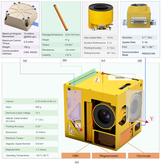
Figure 5.
Performance parameters and hardware modeling diagrams of (a) reaction wheel, (b) magnetorquer, (c) star sensor, (d) sun sensor, and (e) plug-and-play attitude measurement and control system (PnP ADCS).
4. Results and Discussion
4.1. Simulation Experiment
4.1.1. Simulation Experiment Procedure
Figure 6 illustrates the data link in the process of magnetic field measurement. The simulation experiment consists of two main components: the environment and the control algorithm. The environment processes the expected output from the control algorithm in terms of reaction wheel speeds and magnetorquer outputs. This helps in accurately emulating how the satellite’s hardware would respond in a real-world setting. The subsequent attitude and related physical parameters are gauged using noise-inclusive simulation models of star sensors, sun sensors, gyroscopes, and GNSS. These measurements are then relayed to the control computer, serving as inputs for the next instance of attitude control. Orbit propagation calculates orbital information by incorporating the primary perturbations near the LEO orbit, such as the Earth’s fourth-order non-spherical gravitational harmonics, in conjunction with the satellite’s attitude estimation. The GVCA estimates the magnetic field of the system by utilizing the outputs of star sensors, magnetorquers, and reaction wheels. In the depicted scenario, the star tracker measures the relative attitude of the system in the inertial frame based on a star map generated by a star simulator. This attitude is represented in the form of ZYX Euler angles. By including differential calculations, these Euler angles are converted into angular velocity, and subsequent differentiation yields angular acceleration. In addition, the simulation experiment consists of three main phases: the despin phase, the sun-pointing phase (accompanied by the desaturation phase), and the Earth-pointing phase (accompanied by the desaturation phase), corresponding to the time intervals , , and , respectively.
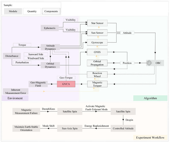
Figure 6.
Simulation software block diagram and simulation experiment control flowchart.
In order to validate the proposed approach and the system described in this paper, typical initial conditions for simulation experiments were set up as shown in Table 1.

Table 1.
Initial conditions for simulation experiments.
4.1.2. Performance of GVCA
As illustrated in Figure 7, the satellite sequentially works in despin mode, sun-pointing mode, and Earth-pointing mode. Hence, the performance of GVCA was evaluated on three fronts. The GVCA was designed to estimate the magnetic field by exerting an output magnetic moment of a magnetorquer in an unknown magnetic field and observing the acceleration of a rigid body with a constant moment of inertia, leveraging Euler’s equations. Figure 7 illustrates the simulation results of this magnetic field estimation approach. Specifically, Figure 7 showcases the measurement efficacy in despin mode as well as during the desaturation processes in both the sun-pointing and Earth-pointing modes. Outputs from the magnetorquers during the simulation are depicted in Figure 7a,c, while the angular acceleration measurements are displayed in Figure 7b,d. These measurements serve as inputs to the GVCA. The angular acceleration is derived from gyroscopes and star sensors, while the magnetic moment output is based on the preceding time step output from the magnetorquers. By utilizing the methods delineated in the algorithm section and applying a Kalman filter, we achieved the gradually converging magnetic field measurements as portrayed in Figure 7e,g. Illustrated in Figure 7f,h, it is evident that the angular velocity of the satellite and the speed of the reaction wheel decrease and the ADCS performs on-orbit despin and desaturation tasks. The magnetic field estimation increasingly converges with the environmental magnetic field values, while Figure 7f,h substantiate the successful execution of the despin and desaturation tasks.
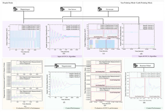
Figure 7.
Performance testing of the GVCA. (a) Output of the magnetorquer, (b) angular acceleration, (c) output timing and operational sequence of the magnetorquer, (d) measured angular velocity results, (e) comparison between the triaxial magnetic field obtained by the GVCA and the true value measured by the magnetometer, (f) despin effect in despin mode, (g) comparison between the triaxial magnetic field obtained by the GVCA and the true value measured by the magnetometer, and (h) change in the triaxial reaction wheel speed during desaturation, in both sun-pointing mode and Earth-pointing mode.
4.1.3. Performance of ADCS
The simulation test encompassed three distinct control phases, each benchmarked using specific evaluation criteria. For the despin mode, the angular velocity changes were assessed; the sun-pointing mode focused on the angle between the z-axis and the solar vector in a body frame; and the Earth-pointing mode evaluated the Euler angle difference between the body frame and the orbital coordinate frame in the inertial space. The relative orbital attitudes for the simulation stages are illustrated in Figure 8a–c. Derived from attitude differentiation, Figure 8d–f display the angular velocities. As depicted in Figure 8d, during the despinning process, the satellite’s triaxial angular velocities decreased in an oscillatory fashion from ±8.5 degree/s to ±0.2 degree/s, manifesting a significant control effect. Figure 8g showcases the desaturation performance of the three reaction wheels, while Figure 8h indicates four independent desaturation phases. In Figure 8k, the Euler angles with respect to the orbital frame fluctuated primarily within a range of . However, there were intermittent drifts every 5600 s in the roll axis due to the interference of the short-term failure of one of the star trackers caused by sunlight and the low measurement accuracy of the star tracker’s roll axis. Based on the displayed data, the satellite demonstrated excellent alignment performance during the Earth-pointing process. Lastly, as shown in Figure 8l, the angle between the body frame’s solar vector and the z-axis consistently remained under in the non-Earth-shadow region, providing a primary foundation for sun-pointing tasks. In addition, there are also cyclical fluctuations per single orbital period due to the influence of the Earth-shadow zone.
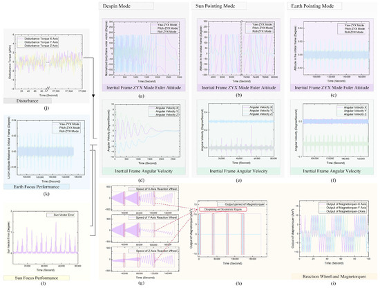
Figure 8.
Performance of attitude determination and control system (ADCS) in a simulation experiment. (a) Attitude in despin mode; (d) its corresponding angular velocity. (b) Attitude in sun-pointing mode; (e) its related angular velocity. (c) Overall process in Earth-pointing mode, including the despin, sun-pointing, and Earth-pointing modes. (f) Operational time intervals of the magnetorquer. (g) Alternating operation flow of the magnetorquer. (h) Effect of desaturation during magnetorquer operation. (i) Gaussian white disturbance torque noise in the simulation. Evaluation metrics for pointing modes: (j) relative attitude errors in Earth-pointing; (k) angular discrepancy in sun-pointing mode between the z-axis of the body frame and the solar vector. The Gaussian white random disturbance torque noise during the simulation experiment is portrayed in (l).
4.1.4. Additional Simulation Experiments
To provide a comprehensive assessment of the methodology proposed in this paper, we conducted multiple sets of simulation experiments under various initial conditions. The simulation results are presented in Table 2.

Table 2.
Results of simulation experiments with various initial conditions.
The results from Table 2 reveal that the presented method consistently exhibited a strong performance across simulation experiments conducted under various initial conditions. It effectively and accurately perceived the magnetic field vector, leading to high-performance attitude control.
4.2. Space Environment Simulation Air-Floating Experiment
4.2.1. Laboratory Setup
In the depicted experimental configuration of Figure 9, the air-bearing table is positioned within the magnetic field simulator. The air from the storage tank is channeled sequentially through the compressor and air dryer, subsequently being expelled atop the air-bearing table to generate a levitating effect. The ADCS is centrally mounted on this air-bearing table. The star-field simulator’s field of view encompasses the star sensor’s field of view. Encasing the air-bearing table, the magnetic field simulator ensures that a uniform magnetic field is provisioned within its internal space.
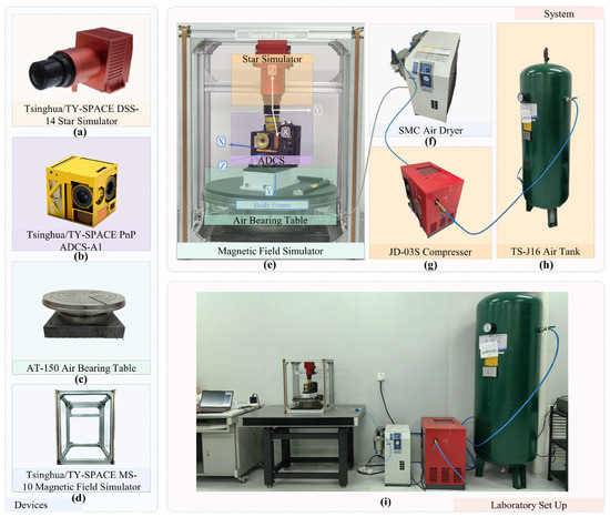
Figure 9.
Photographs of the (a) star sensor, (b) ADCS, (c) air-bearing table, (d) magnetic field simulator, (e) ADCS testing and simulation platform, (f) air dryer, (g) compressor, (h) air storage tank, and (i) laboratory set-up.
Due to the relatively low rotation amplitude of the other two axes on the air-bearing table, only the inertial z-axis direction can rotate freely. In the experimental results, it can be observed that the single-axis angular velocity was substantial. The simulated experimental scene was a ground-stable mode under a low earth orbit (LEO), while the angular velocity coincided with its orbital angular velocity.
In the laboratory setup, the star sensor determined the relative attitude of the body frame with respect to the inertial frame based on the star map provided by the star simulator, while the attitude was expressed in ZYX Euler angles. Differential calculations were employed to convert Euler angles into angular velocities, which were then differentiated again to determine angular acceleration. Due to the limited rotation range of the other two axes of the air-bearing table, only the inertial z-axis was free to rotate. We verified the single-axis despin and desaturation effect using the air-bearing platform method proposed in this paper. In the experimental results, a significant angular velocity can be observed only along a single axis.
4.2.2. Performance of Air-Floating Table
Figure 10 illustrates the performance test results of the air-bearing table utilized in the experimental apparatus to emulate a space dynamics environment. Figure 10a displays the attitude variation data when the air-bearing table is in a free-rotation state. Due to the presence of eccentric torques and vortex torques, the ADCS encountered substantial disturbance torques during the experiment, leading to a gradual increase in angular velocity. As can be inferred from Figure 9b,c, the disturbance torques resulted from a combination of sinusoidal torques and constant-value disturbance torques. In the section enclosed by the red frame in Figure 10c, where the angular velocity experienced minimal fluctuations over time, or in other words, where the angular acceleration approached zero, there was a region with relatively low disturbance on the air-bearing table. Hence, within intervals of reduced disturbance, as highlighted by the red frame, there was an enhancement in the performance of both the algorithm and ADCS. Conversely, in intervals of heightened disturbance, represented by the purple frame, there was a decline in the system’s and the algorithm’s performance.
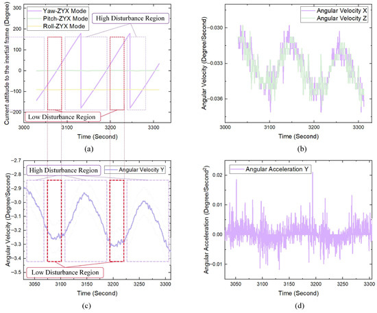
Figure 10.
Uncontrolled test experiment conducted to observe the interference of the air-bearing table on ADCS control. (a) Euler angle variations in the body frame relative to the inertial frame during the experiment. (b) Angular velocity of the body frame in the inertial frame along the x- and z-axes. (c) Angular velocity along the y-axis, derived from differentiation of the Euler angles. (d) Angular acceleration along the y-axis, obtained from further differentiation of the y-axis angular velocity.
4.2.3. Performance of GVCA in Earth-Pointing Phase
In the context of the air-floating experiment using a space environment simulation, this section presents the GVCA and its upstream and downstream data. By analyzing the results from the space environment simulation experiments, the performance of the algorithm is validated. The star sensor measured the triaxial Euler angles of the body frame relative to the inertial frame based on the star map displayed by the star simulator, as shown in Figure 11a. By performing a second-order differentiation on these angles, we obtained the triaxial angular velocities depicted in Figure 11b,f, respectively. Given that the primary goal of this experiment was to validate the single-axis despin effect, the y-axis angular acceleration (illustrated in Figure 11e) was used as an input for the GVCA in the subsequent computations. The desired outputs for the magnetorquers and reaction wheels, presented in Figure 11c,d, respectively, were provided by the OBC. At each time step, the actual output from the magnetorquers and the feedback on wheel speed from the reaction wheels were utilized as inputs for the next iteration of the algorithm, facilitating the computation of the spatial magnetic field.
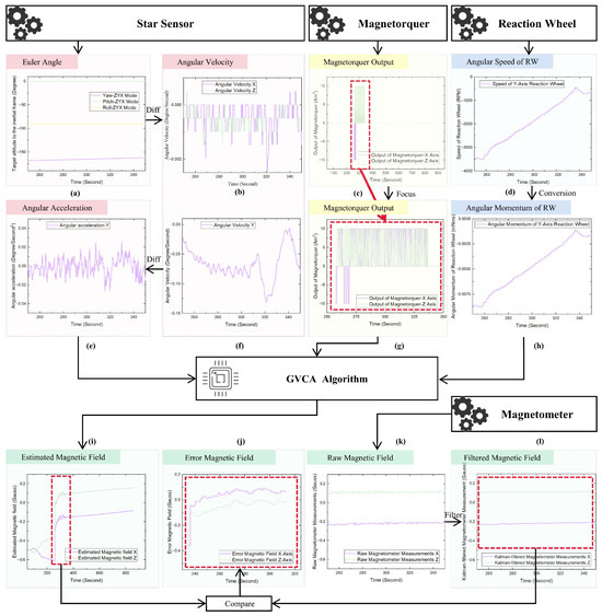
Figure 11.
Performance and data flow representation of the GVCA in Earth-pointing mode: (a) Attitude characterization using Euler angles as measured by star sensors. (b,f) Triaxial angular velocities obtained through attitude differentiation. (c,g) Anticipated magnetorquer outputs under the guidance of the OBC. (d) Rotational velocity of the y-axis reaction wheel. (e) Angular acceleration obtained through angular velocity differentiation. (h) Angular momentum retained by the y-axis reaction wheel. (i) Magnetic field estimations derived from the GVCA. (k) Unfiltered magnetometer measurements of the magnetic field. (l) Data post-smoothing from the magnetometer’s readings. (j) A juxtaposition of the magnetometer’s reference measurements with the values derived from the algorithm. Sections (i–l) (enclosed in a red frame) delineate intervals wherein the magnetorquer is actively outputting.
The GVCA, in conjunction with the aforementioned inputs and a Kalman filter, produced a magnetic field, as depicted in Figure 11i. The magnetic field considered as the ground truth, measured using the magnetometer, is illustrated in Figure 11k. The smoothed magnetic field output, mitigating random noise through a smoothing filter, is presented in Figure 11l. The red dashed box corresponds to the interval where the magnetorquer had its output. During this data segment, the magnetic field continuously converged through calculations within the Kalman filter. Comparing the magnetic field measurements in Figure 11l,i, it can be observed that under the influence of the algorithm, the error gradually converged. One can observe that the measurement error fell within a range of ±0.1 Gauss. This offers foundational environmental awareness for subsequent despin and desaturation operations.
Due to the significantly higher presence of eccentric torques and vortex torques in the ground test platform compared to those in space, there is a certain steady-state error in the magnetic field test results. However, as evidenced by the subsequent ADCS performance test results in this paper, the magnetic field measured using the GVCA algorithm can still support the ADCS in accomplishing despin and desaturation tasks, even in experiments with added difficulty. This also demonstrates the robustness of the algorithm.
4.2.4. Performance of ADCS in Earth-Pointing Phase
In the Earth-pointing phase, the angular velocity initial value is , which, under control, gradually converges to within , as illustrated in Figure 12m. It is notable that during the Earth-pointing control phase under LEO orbit, while the y-axis was perpendicular to the orbital plane, the y-axis angular velocity aligned with its orbital angular velocity of . Meanwhile, as shown in Figure 12k,n, the Euler angle of the body frame relative to the orbital frame gradually converged from the initial to , which can meet the remote sensing requirements of CubeSats.
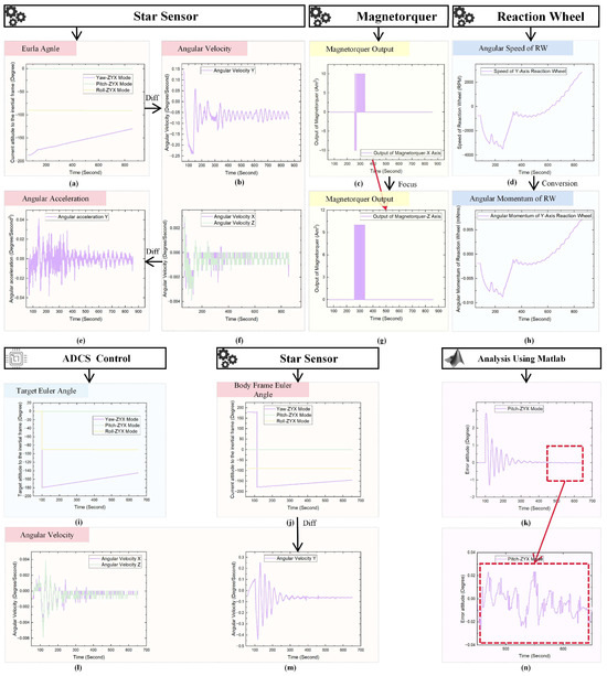
Figure 12.
Performance and data flow representation of the ADCS in Earth-pointing mode. (a) Attitude characterization using Euler angles, as measured by star sensors. (b,f) Triaxial angular velocities obtained through attitude differentiation. Anticipated magnetorquer outputs under the guidance of the OBC of (g) the z-axis and (c) the x-axis. (d) Rotational velocity of the y-axis reaction wheel. (e) Angular acceleration obtained through angular velocity differentiation. (h) Angular momentum retained by the y-axis reaction wheel. (i) Target Euler angle of ADCS. (j) Attitude measured from the start sensor. (l) x- and z-axial and (m) y-axial angular velocity obtained from the differentiation of attitude. Error attitude of ADCS in (k,n) the Earth-pointing phase.
The magnetorquer controlled and output the magnetic moment as required by the algorithm, and the range of outputs was recorded as an input for the GVCA for subsequent calculations. The operational status of the magnetorquer during the entire experimental process is depicted in Figure 12c, with the specific output situation of the magnetorquer between 250 s and 350 s, as shown in Figure 12g. In the first 250 s of the experiment, the reaction wheels accomplish preliminary despinning control, storing the angular momentum of both the ADCS and the pedestal. Subsequently, in the 250 to 300 s time frame during which the magnetorquer operated, the magnetic rods unloaded the reaction wheels.
In Figure 12d,h, we can observe the rotational speeds and the stored angular momentum of the reaction wheels during the experiment. Notably, when the magnetic rods were operational, there was a discernible decline in both the rotational speeds and the stored angular momentum, validating the anticipated desaturation effect. Given that both the rotational speed and torque exert influence on magnetic field measurements, these metrics were integrated as inputs into the GVCA.
Additionally, the significant disturbance torque from the air-bearing platform impacted the attitude control accuracy and stability, leading to the rapid saturation of the flywheel. However, during actual on-orbit operations, the performance of the ADCS would be superior to that of ground experiments, and the saturation rate of the flywheel would be greatly reduced.
4.2.5. Performance in Despin Mode
In both the despin and Earth-pointing modes, the GVCA remains consistent. However, due to the different attitude control tasks being executed, the evaluation criteria for ADCS differ. This subsection will analyze the performance of the GVCA and ADCS during the space environment simulation in despin mode.
Within the GVCA, the estimation results for the Earth’s magnetic field on the x- and y-axes are depicted in Figure 13a,b. It is evident that after the algorithm is initiated, it gradually converges to the vicinity of the magnetic field measured by the magnetometer. Due to the presence of vortex moments and angular moments, there is always a steady-state error in the magnetic field measurements. As demonstrated in Figure 13c, the magnetic field from GVCA, when used for despinning, produced commendable results, effectively reducing the self-spin angular velocity of the ADCS from 2 degrees per second to the desired threshold, 0.2 degrees per second. In the experiment, the angular velocity is solely provided by the star tracker, while during on-orbit operations, the high angular velocity during the despin phase is primarily provided by the gyroscope. However, this has minimal impact on the experimental results, as the disturbance torque from the air bearing overshadows the effects of the gyroscope noise. Moreover, the star tracker also provides a low angular velocity during on-orbit operations.

Figure 13.
Performance of ADCS and GVCA in despin mode. Magnetic field comparison between raw data from magnetometers and the magnetic field generated from GVCA on (a) the x-axis and (b) the y-axis. (c) Despin performance of ADCS utilizing magnetic field measurement, generated from GVCA.
4.2.6. Performance in Sun-Pointing Mode
Similar to the despin mode, the results for the sun-pointing mode are depicted in Figure 14. The magnetic field measurements from the GVCA are shown in Figure 14a,b. During the execution of the desaturation task, the magnetic field measured using the GVCA converged towards the vicinity of the magnetic field measured using the magnetometer. Concurrently, the reaction wheel’s speed decreased from 3000 rpm to approximately 500 rpm. Following the completion of the desaturation phase, due to the torques stored in the reaction wheel, its speed swiftly rose to around 1000 rpm. The error in magnetic field identification and the rapid saturation of the flywheel were primarily due to the significant disturbance torque introduced by the air-bearing table. The actual on-orbit disturbance torque will be much smaller than the disturbance torque in the experiments, so the identification accuracy will be closer to the simulated conditions. Additionally, the saturation speed of the flywheel will significantly decrease.

Figure 14.
Performance of ADCS and GVCA in sun-pointing mode. Magnetic field comparison between raw data from magnetometers and magnetic field generated from GVCA on (a) the x-axis and (b) the y-axis. (c) Desaturation performance of ADCS utilizing magnetic field measurements generated from GVCA.
4.2.7. Additional Laboratory Experiments
In order to furnish a comprehensive evaluation of the proposed methodology, a series of laboratory experiments was conducted under diverse initial conditions. The resultant data from these experiments are meticulously elucidated in Table 3.

Table 3.
Laboratory experiment results in various initial conditions.
The findings derived from Table 3 demonstrate the consistent and robust performance of the presented method in a range of laboratory experiments conducted under varying initial conditions. This method effectively and precisely perceives the magnetic field vector, ultimately resulting in a high level of performance in terms of attitude control.
5. Conclusions
In this research, we present a novel on-orbit, dynamic-sensing, magnetic, fault-tolerant control method to address iADCS failures caused by magnetic interference, which further leads to the failure of CubeSats remote sensing missions. This approach entirely eliminates the reliance on magnetic field sensors, thereby circumventing the spatial constraints, high computational consumption, and performance degradation associated with existing magnetometer-dependent methods, making it better suited for the iADCS of remote sensing CubeSats. The proposed temporal expansion geomagnetic vector calculation method effectively decouples observation equations in three axes through control segmentation in the time domain, resolving issues related to the singularity of the Kalman coefficient matrix and achieving real-time sensing of the magnetic field vector with low computational consumption. The fault-tolerant control strategy and multi-mode control laws derived from real-time sensing of the magnetic field vector ensure high control performance.
Initially, we validated the effectiveness of the proposed method through numerical simulations set up based on real-world engineering environments. Furthermore, to accurately evaluate our approach and support the development of CubeSats for remote sensing missions, we developed a PnP ADCS and a comprehensive physical ground-based experiment system, enabling experimental verification under conditions approximating actual space environments. The ground experiment results demonstrate that the proposed method enables high-performance attitude control in the presence of faults induced by magnetic interference, with an attitude control accuracy reaching 0.02 degrees and attitude stability better than 0.003 degrees/s. In conclusion, the methods and systems presented in this paper can be leveraged to support the highly reliable construction of high-precision remote sensing CubeSats.
Author Contributions
Conceptualization, S.F., F.X. and Z.Y.; data curation, S.F., Z.C., X.C. and X.L.; formal analysis, S.F. and Z.C.; funding acquisition, F.X. and Z.Y.; investigation, S.F., Z.C. and X.C.; methodology, S.F. and Z.C.; project administration, F.X. and Z.Y.; resources, S.F.; software, S.F. and X.L.; supervision, F.X. and Z.Y.; validation, S.F. and X.L.; visualization, S.F. and Z.C.; writing—original draft, S.F., Z.C. and X.C.; writing—review and editing, S.F., Z.C. and X.C. All authors have read and agreed to the published version of the manuscript.
Funding
This research was funded by the National Natural Science Foundation of China under Grant 51827806 and in part by the Tencent Foundation under the Xplorer Prize.
Data Availability Statement
The data presented in this study are available on request from the corresponding author. The data are not publicly available due to privacy restrictions.
Acknowledgments
We gratefully acknowledge the support of the State Key Laboratory of Precision Measurement Technology and Instruments.
Conflicts of Interest
The authors declare no conflict of interest.
References
- Kawa, B.; Śniadek, P.; Walczak, R.; Dziuban, J. Nanosatellite Payload for Research on Seed Germination in a 3D Printed Micropot. Sensors 2023, 23, 1974. [Google Scholar] [CrossRef]
- Rashed, M.I.; Bang, H. A study of cognitive computing in nanosatellite constellations for synergic autonomy in CisLunar space. Adv. Space Res. 2023. [Google Scholar] [CrossRef]
- Thomas, M.; Trenti, M.; Sanna, A.; Campana, R.; Ghirlanda, G.; Řípa, J.; Burderi, L.; Fiore, F.; Evangelista, Y.; Amati, L. Localisation of gamma-ray bursts from the combined SpIRIT+ HERMES-TP/SP nano-satellite constellation. Publ. Astron. Soc. Aust. 2023, 40, e008. [Google Scholar]
- Ruf, C.S.; Gleason, S.; Jelenak, Z.; Katzberg, S.; Ridley, A.; Rose, R.; Scherrer, J.; Zavorotny, V. The CYGNSS nanosatellite constellation hurricane mission. In Proceedings of the 2012 IEEE International Geoscience and Remote Sensing Symposium, Munich, Germany, 22–27 July 2012; pp. 214–216. [Google Scholar]
- Nakasuka, S.; Sako, N.; Sahara, H.; Nakamura, Y.; Eishima, T.; Komatsu, M. Evolution from education to practical use in University of Tokyo’s nano-satellite activities. Acta Astronaut. 2010, 66, 1099–1105. [Google Scholar] [CrossRef]
- Funase, R.; Inamori, T.; Ikari, S.; Ozaki, N.; Koizumi, H. Initial operation results of a 50kg-class deep space exploration micro-spacecraft PROCYON. In Proceedings of the 29th Annual AIAA/USU Conference on Small Satellites, Logan, UT, USA, 8–13 August 2015. [Google Scholar]
- Nagel, G.W.; Novo, E.M.L.d.M.; Kampel, M. Nanosatellites applied to optical Earth observation: A review. Rev. Ambiente Água 2020, 15, 3. [Google Scholar] [CrossRef]
- Tamire, N.A.; Kim, H.-D. Effective Video Scene Analysis for a Nanosatellite Based on an Onboard Deep Learning Method. Remote Sens. 2023, 15, 2143. [Google Scholar] [CrossRef]
- Evans, D.; Merri, M. OPS-SAT: A ESA nanosatellite for accelerating innovation in satellite control. In Proceedings of the SpaceOps 2014 Conference, Pasadena, CA, USA, 5–9 May 2014; p. 1702. [Google Scholar]
- Bedington, R.; Bai, X.; Truong-Cao, E.; Tan, Y.C.; Durak, K.; Villar Zafra, A.; Grieve, J.A.; Oi, D.K.; Ling, A. Nanosatellite experiments to enable future space-based QKD missions. EPJ Quantum Technol. 2016, 3, 12. [Google Scholar] [CrossRef]
- McCarthy, S.; Crawford, S.; Wood, C.; Lewis, M.D.; Jolliff, J.K.; Martinolich, P.; Ladner, S.; Lawson, A.; Montes, M. Automated Atmospheric Correction of Nanosatellites Using Coincident Ocean Color Radiometer Data. J. Mar. Sci. Eng. 2023, 11, 660. [Google Scholar]
- Klyushnikov, V.Y. Status and prospects of developing commercial nano satellite constellations for Earth remote sensing. AIP Conf. Proc. 2021, 2318, 190008. [Google Scholar]
- Hakim, P.R.; Hasbi, W.; Syafrudin, A.H. ADCS requirements of Lapan-A3 satellite based on image geometry analysis. In Proceedings of the 2014 IEEE International Conference on Aerospace Electronics and Remote Sensing Technology, Yogyakarta, Indonesia, 13–14 November 2014; pp. 142–146. [Google Scholar]
- Foster, C.; Hallam, H.; Mason, J. Orbit determination and differential-drag control of Planet Labs CubeSat constellations. arXiv 2015, arXiv:1509.03270. [Google Scholar]
- Villela, T.; Costa, C.A.; Brandão, A.M.; Bueno, F.T.; Leonardi, R. Towards the thousandth CubeSat: A statistical overview. Int. J. Aerosp. Eng. 2019, 2019, 1–13. [Google Scholar]
- Poghosyan, A.; Golkar, A. CubeSat evolution: Analyzing CubeSat capabilities for conducting science missions. Prog. Aerosp. Sci. 2017, 88, 59–83. [Google Scholar]
- Bedingfield, K.L.; Leach, R.D. Spacecraft System Failures and Anomalies Attributed to the Natural Space Environment; National Aeronautics and Space Administration, Marshall Space Flight Center: Huntsville, AL, USA, 1996; Volume 1390.
- Dubock, P.; Spoto, F.; Simpson, J.; Spencer, D.; Schutte, E.; Sontag, H. The Envisat satellite and its integration. ESA Bull. 2001, 106, 26–45. [Google Scholar]
- Harland, D.M.; Lorenz, R.D. Attitude control system failures. In Space Systems Failures; Praxis: Gainesville, Georgia, 2005; pp. 211–226. [Google Scholar] [CrossRef]
- Tafazoli, M. A study of on-orbit spacecraft failures. Acta Astronaut. 2009, 64, 195–205. [Google Scholar] [CrossRef]
- Hasan, M.N.; Haris, M.; Qin, S. Fault-tolerant spacecraft attitude control: A critical assessment. Prog. Aerosp. Sci. 2022, 130, 100806. [Google Scholar]
- Yin, S.; Xiao, B.; Ding, S.X.; Zhou, D. A review on recent development of spacecraft attitude fault tolerant control system. IEEE Trans. Ind. Electron. 2016, 63, 3311–3320. [Google Scholar] [CrossRef]
- Ennaciri, T.; Abbassi, A.E.; Mrani, N.; Foshi, J. Attitude Control of LEO Satellite via LQR Based on Reaction Wheels Versus Magnetorquer. In Proceedings of the International Conference on Artificial Intelligence and Smart Environment, Errachidia, Morocco, 24–26 November 2022; pp. 264–269. [Google Scholar]
- Yang, Y. Spacecraft attitude and reaction wheel desaturation combined control method. IEEE Trans. Aerosp. Electron. Syst. 2017, 53, 286–295. [Google Scholar] [CrossRef]
- Steyn, W. A Multimode Attitude Determination and Control System for SUNSAT. Ph.D. Thesis, Stellenbosch University, Stellenbosch, South Africa, December 1995. [Google Scholar]
- Broadfoot, R.M.; Miles, D.M.; Holley, W.; Howarth, A.D. In situ calibration of the Swarm-Echo magnetometers. Geosci. Instrum. Methods Data Syst. 2022, 11, 323–333. [Google Scholar] [CrossRef]
- Montalvo, C.J.; Givens, A.; Cobar, M.J.; Sherman, W.; Franklin, C.; Patrick, W.M.; Godfrey, A. Guidance, Navigation and Control Subsystem Design for ABEX Satellite. In Proceedings of the AIAA SCITECH 2022 Forum, San Diego, CA, USA, 3–7 January 2022; p. 1588. [Google Scholar]
- Xing, Y.; Low, K.; Pham, M. Distributed Model Predictive Control of satellite attitude using hybrid reaction wheels and magnetic actuators. In Proceedings of the 2012 IEEE Symposium on Industrial Electronics and Applications, Bandung, Indonesia, 23–26 September 2012; pp. 230–235. [Google Scholar]
- Miles, D.M.; Howarth, A.D.; Enno, G.A. In situ calibration of offsetting magnetometer feedback transients on the Cassiope spacecraft. Geosci. Instrum. Methods Data Syst. 2019, 8, 187–195. [Google Scholar] [CrossRef]
- Finley, M.G.; Broadfoot, R.M.; Shekhar, S.; Miles, D.M. Identification and Removal of Reaction Wheel Interference From In-Situ Magnetic Field Data Using Multichannel Singular Spectrum Analysis. J. Geophys. Res. Space Phys. 2023, 128, e2022JA031020. [Google Scholar] [CrossRef]
- Finley, M.; Miles, D.; Shekhar, S.; Steele, K. Beyond Bandpass: Time-Varying Interference Mitigation for In-Situ Magnetic Field Data using Multichannel Singular Spectrum Analysis. In Proceedings of the AGU Fall Meeting Abstracts, Chicago, IL, USA, 12–16 December 2022; p. SH32D-1782. [Google Scholar]
- Colagrossi, A.; Lavagna, M. Fault tolerant attitude and orbit determination system for small satellite platforms. Aerospace 2022, 9, 46. [Google Scholar] [CrossRef]
Disclaimer/Publisher’s Note: The statements, opinions and data contained in all publications are solely those of the individual author(s) and contributor(s) and not of MDPI and/or the editor(s). MDPI and/or the editor(s) disclaim responsibility for any injury to people or property resulting from any ideas, methods, instructions or products referred to in the content. |
© 2023 by the authors. Licensee MDPI, Basel, Switzerland. This article is an open access article distributed under the terms and conditions of the Creative Commons Attribution (CC BY) license (https://creativecommons.org/licenses/by/4.0/).