Abstract
Small ships in remote sensing images have blurred details and are difficult to detect. Existing algorithms usually detect small ships based on predefined anchors with different sizes. However, limited by the number of different sizes, it is difficult for anchor-based methods to match small ships of different sizes and structures during training, as they can easily cause misdetections. In this paper, we propose a hybrid anchor structure to generate region proposals for small ships, so as to take full advantage of both anchor-based methods with high localization accuracy and anchor-free methods with fewer misdetections. To unify the output evaluation and obtain the best output, a label reassignment strategy is proposed, which reassigns the sample labels according to the harmonic intersection-over-union (IoU) before and after regression. In addition, an adaptive feature pyramid structure is proposed to enhance the features of important locations on the feature map, so that the features of small ship targets are more prominent and easier to identify. Moreover, feature super-resolution technology is introduced for the region of interest (RoI) features of small ships to generate super-resolution feature representations with a small computational cost, as well as generative adversarial training to improve the realism of super-resolution features. Based on the super-resolution feature, ship proposals are further classified and regressed by using super-resolution features to obtain more accurate detection results. Detailed ablation and comparison experiments demonstrate the effectiveness of the proposed method.
1. Introduction
Optical remote sensing image ship target detection technology plays an important role in sea area monitoring, marine pollution detection, maritime traffic management, and military reconnaissance. Research on ship target detection technology is of great significance. Due to the great success of object detection algorithms based on convolutional neural networks [1,2,3,4,5,6,7,8,9,10], many researchers use similar techniques to achieve ship detection [11,12,13,14,15,16,17,18,19,20,21]. However, it is still a very challenging task to accurately locate small ships from optical remote sensing images.
Small ship targets in remote sensing images have fewer pixels and blurry details, making them difficult to successfully detect. Most of the existing ship detection methods generate multi-scale feature maps via the feature pyramid structure [22], and then set anchors with different sizes on shallow feature maps that have more detailed information to detect small ships. During the training process, the anchor is only matched with nearby ships that have a similar size (that is, the IoU reaches the preset threshold) to generate positive samples for regression, which reduces the difficulty of parameter prediction and improves the localization accuracy of the detection.
However, small ships have fewer pixels and the IoU changes caused by size and location offset are drastic, which greatly increases the difficulty of matching with the anchor. When predefined sizes of the anchor are not close to the ground-truth bounding box, it is difficult for the algorithm to match a sufficient number of positive samples for small ship targets during the training process. In this way, the training is insufficient, resulting in a decrease in detection performance and even misdetections. Different from anchor-based methods, anchor-free methods do not require predefined anchors and can freely match objects of different sizes without IoU restrictions during training. This enables the anchor-free method to match more positive samples for small ship targets beyond the predefined size of the anchor, making the training more adequate and reducing misdetections. However, due to the lack of prior size information, the localization accuracy of anchor-free methods is usually lower than that of anchor-based methods.
To resolve this contradiction, we propose a small ship detection method based on hybrid anchor structure and feature super-resolution. The proposed method combines the advantages of both anchor-based methods and anchor-free methods. Firstly, an adaptive feature pyramid is proposed, which combines the rich detail information of shallow features to predict the spatial location weight of deep features, so as to enhance the information of important locations in a more targeted manner, making it easier for small ships to be classified and located. Then, based on the shallow features of the adaptive feature pyramid, two parallel anchor-based and anchor-free detection branches are set to detect small ships. The two detection branches give full play to the high localization accuracy of anchor-based methods and the high recall of anchor-free methods.
During training, the network minimizes the losses of the two detection branches to extract ship features with complementary advantages, thereby improving the detection accuracy of both branches. During the test phase, in order to preserve better detection results of each branch, the output results need to be merged according to the classification scores of the two branches. However, due to the different definitions of positive samples, the classification scores of the anchor-based branch and anchor-free branch have different meanings and cannot be directly used for comparison. Although they have complementary advantages, the difference in output evaluation makes it difficult for the two branches to obtain their respective optimal outputs.
To solve this problem, we propose a label reassignment strategy. The proposed strategy comprehensively considers the localization accuracy before and after regression to reassign the sample labels in each iteration, so that the two detection branches can obtain unified output evaluations. The classification score after label reassignment is able to better reflect the localization accuracy of the bounding box, which further narrows the difference between the classification and regression tasks, thereby optimizing the training process. When the training is completed, the algorithm retains ship proposals with higher accuracy according to the classification scores of the two branches, making use of the complementary roles of the anchor-based branch and the anchor-free branch.
In addition, although the hybrid anchor structure can effectively reduce misdetections, small ships in remote sensing images still lack detail information, which limits further improvement of the detection. To solve this problem, we perform feature super-resolution on the RoI features of small ships to recover the missing details. Specifically, a feature super-resolution network is proposed, which is composed of recursive residual modules and densely connected structures. The feature super-resolution network maps RoI features of small ships into super-resolution features with more detailed information, while avoiding a lot of computation caused by super-resolution reconstruction to the whole image. With help of the more detailed information of super-resolution features, the proposed method is able to accurately locate small ship targets and obtain better detection results.
2. Related Work
2.1. Anchor-Free Detection Methods
The anchor-based ship detection methods achieve good detection performance, but also have two main problems: (1) They rely on a large number of dense anchors to cover objects of different sizes, which leads to an imbalance of positive and negative samples. (2) The anchor requires manual setting for hyperparameters such as scale and aspect ratio. It is difficult to manually adjust these hyperparameters. Therefore, in view of the defects of the anchor, researchers have proposed anchor-free object detection methods.
Anchor-free object detection methods can be roughly divided into the two categories of corner-based methods and keypoint-based methods. The corner-based method regards the object bounding box as a pair of key points in the upper left and lower right corners and achieves object localization through the corners. Law et al. [23] propose the CornerNet algorithm, which sets two branches on the basis of the backbone network to predict two key points of the upper left corner and the lower right corner of the bounding box, respectively. At the same time, each branch also generates a corresponding embedding vector for the key point, judging whether the two key points belong to the same object through the distance between the embedding vectors. The keypoint-based method makes predictions based on the center point. Zhou et al. [24] first input the image into a fully convolutional neural network to generate the heatmap. Then, the center point of the object is predicted according to the peak points in the heat map. Finally, the width and height of the bounding box are regressed based on the center point.
Chen et al. [25] first use a fully convolutional neural network to locate the three key points of the ship’s bow, stern, and center point. Then, the bounding box of the ship is generated based on these three key points. Meanwhile, the feature fusion and enhancement module is designed to deal with environmental disturbances. In order to reduce false detections, Zhang et al. [26] set two priority branches to the CornerNet. Among them, one recall priority branch is used to reduce false negative samples, and another accuracy priority branch is used to reduce false positive samples. Moreover, the combination of the bidirectional feature pyramid structure and the inference part of YOLOv3 [27] further improves the detection performance of side-by-side ships. Gao et al. [28] propose a dense attention feature integration module, which combines multi-scale features through dense connection and iterative fusion to suppress background interference, thereby improving the generalization performance of the network.
Since the anchor-free method avoids the large amount of computation brought by the predefined anchors, this kind of method usually has a faster running speed. However, compared with anchor-based detection methods, anchor-free methods have poor localization accuracy due to the lack of prior information about the size of the bounding box.
2.2. Feature Super-Resolution
At present, multi-scale ship detection methods in remote sensing images have achieved good results on large ships and medium-sized ships, but the detection performance for small ships still needs to be improved. Small ships occupy a small number of pixels in the image, resulting in a lack of detailed information in the features extracted by the shallow network, which limits the improvement of detection accuracy.
Therefore, in order to more accurately detect small ships, it is natural to perform the super-resolution operation on the images to obtain high-resolution images with rich details. The basic method of image super-resolution is to use bilinear interpolation to upsample the input image, but the recovered image details are relatively rough. In recent years, with the development of deep learning technology, convolutional neural networks are widely used for image super-resolution, and these can obtain a super-resolution image with clearer details [29,30,31,32,33,34,35,36,37]. Based on this idea, Wang et al. [38] first generate high-resolution images through an image super-resolution network, and then perform object detection based on the high-resolution images. Although this method can improve the detection accuracy for small objects, high-resolution images significantly increase the computational complexity of the algorithm.
In addition to image super-resolution, another method is to perform super-resolution on image features. The purpose of image super-resolution is to increase the resolution of the image for a better visual perception, while feature super-resolution supplements information for a given feature (for example, features extracted from low-resolution images or features of small objects), thereby improving the accuracy of the algorithm on various computer vision tasks. For example, Tan et al. [39] design an FSR-GAN model based on generative adversarial networks, which effectively improves the resolution of features and boosts the image retrieval performance on multiple datasets.
Similarly, for the object detection task, Li et al. [40] use a generative adversarial network to perform feature super-resolution on the RoI (region of interest) features of small objects, transferring shallow features to deep features through the residual structure to supplement detail information for small objects. Compared with image super-resolution, RoI feature super-resolution is closer to target discrimination and can achieve computational sharing to the greatest extent, thereby reducing the amount of computation. However, this method only uses the shallow features of the small object for feature enhancement without real high-resolution features as supervision. Therefore, the obtained results cannot reflect the real details well.
3. The Proposed Method
Following the two-stage detection pipeline, the overall framework of our method is shown in Figure 1 and consists of four parts: backbone network, adaptive feature pyramid, hybrid anchor detection structure, and RoI feature super-resolution.
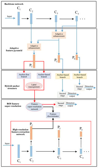
Figure 1.
The pipeline of the proposed method.
The ResNet-50 [41] model is used as the backbone network. Firstly, an adaptive feature pyramid is constructed based on the output feature maps of different depths of the backbone network. The spatial information is adaptively enhanced via an adaptive enhancement module to highlight the features of important locations. Then, a hybrid anchor detection structure is proposed to take full advantages of both anchor-based methods and anchor-free methods. In hybrid anchor structure, an anchor-based detection branch and an anchor-free detection branch are set based on the output feature maps of the layer to detect small ships. Since the definitions of positive and negative samples of the two detection branches are different, directly merging the output results according to the prediction score will lead to a performance drop. Therefore, we proposes a label reassignment strategy, which reassigns the label of training samples according to their localization accuracy before and after regression. After label reassignment, the two different detection branches can obtain a unified output evaluation, so as to better merge the output results.
Next, in the RoI feature super-resolution part, the feature super-resolution network performs super-resolution reconstruction on the RoI features of small ships. The feature super-resolution process supplements missing details of small ships, which is beneficial for further classification and regression. During training, the high-resolution feature extraction network extracts high-resolution RoI features of small ships from high-resolution images as the ground-truth of the feature super-resolution network. Moreover, to obtain more realistic super-resolution features, the feature super-resolution network is optimized by means of generative adversarial training with the help of the feature discriminator. Finally, the super-resolution RoI features generated by the feature super-resolution network are classified and regressed to obtain the final detection result.
3.1. Adaptive Feature Pyramid
The feature pyramid structure fuses deep features to shallow layers step by step, supplementing rich semantic information for the shallow features with more detailed information. The traditional feature pyramid structure fuses the features of two adjacent layers by element-wise addition. However, this fusion approach cannot adaptively adjust the weight according to the changes of input features. In the layer-by-layer process of feature fusion, the semantic information of different spatial locations cannot be distinguished, so the important location information transmitted to the bottom layer is weakened, thus affecting the detection performance for small ship targets.
Aiming at this defect of the traditional feature pyramid, we propose an adaptive feature pyramid structure. The core of the adaptive feature pyramid is the adaptive feature enhancement module. This module uses shallow features with rich spatial information to adaptively enhance the different locations of the deep features, so that the features on important locations in the fusion result are more salient, which is convenient for detecting small ship targets.
The structure of the adaptive feature pyramid is shown in Figure 2. , , , and represent the output feature maps from the second stage to the fifth stage of the ResNet-50 network model, respectively. The feature map of the layer goes through the convolutional layer to reduce the number of channels, and the top-level feature map of the pyramid is obtained. Then, is 2× upsampled to match the spatial size of , while is channel-reduced by 8 to get the same number of channels as . Next, together with are used as the input of the adaptive enhancement module. Since has low resolution and less spatial information, while has high resolution and richer spatial information, the adaptive enhancement module combines the information of to enhance the spatial information of to obtain the enhanced feature map. The enhanced feature map is added to the feature map of the layer after dimension reduction, and the fused sub-top layer feature map is obtained. The method then iterates in the same way to get and the bottom-level feature map .
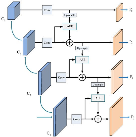
Figure 2.
Structure of the adaptive feature pyramid. AFE: adaptive feature enhancement.
The structure of the adaptive enhancement module is shown in Figure 3. The input feature maps and are both in size. First, and (i = 2, 3, 4) are spliced along the channel, and a convolutional layer is set for channel fusion to obtain the size output feature map. Then, channel reduction is performed through a convolutional layer to halve the number of channels. Next, a spatial weight map of size is obtained via channel average pooling and sigmoid activation function. Finally, the spatial weight map is used to weight to get the enhanced feature . The adaptive enhancement module predicts the fusion weight for each location of high-level features according to the feature map to be fused. In this way, features of important locations are enhanced while features of irrelevant locations are ignored, thereby achieving better feature fusion.
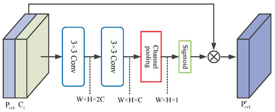
Figure 3.
Structure of the adaptive enhancement module.
3.2. Hybrid Anchor Detection Structure
Mainstream object detection algorithms widely use anchor boxes to locate objects. These methods predefine anchors with different scales and aspect ratios as initial candidates for objects, providing prior information about the object size. The design of anchors can effectively improve the localization accuracy of the detection, but there are still two main defects: (1) Since the size of the object is unknown, the algorithm needs to set multiple anchor boxes of different sizes at each pixel location, which increases the computational burden of the network. (2) The anchor introduces the two hyperparameters of scale and aspect ratio. When these hyperparameters are not set properly, the object cannot be matched to a sufficient number of positive samples, resulting in a decrease in detection performance.
The anchor-free method improves on these defects. This kind of method directly predicts the distance from the object bounding box to the current pixel location without predefining the size of the bounding box. Since it is not limited by the size of the object, anchor-free methods can better match small objects that are difficult to cover by the anchor, thus effectively reducing misdetections.
The anchor-based method can better detect ships of regular size. However, for small ships, especially those with large aspect ratios, a small offset may lead to a dramatic change in the IoU between the anchor and ground-truth bounding boxes. In this case, it is difficult to reach the threshold of positive samples, which can easily cause misdetections. Therefore, in order to take full advantages of both anchor-based methods and anchor-free methods, we set two parallel anchor-based and anchor-free detection branches at the bottom of the adaptive feature pyramid. Among them, the anchor-based detection branch can improve the localization accuracy of small ships, and the anchor-free detection branch can help to avoid misdetections. On this basis, a label reassignment strategy is proposed to unify the output evaluations of the two branches, so as to better combine the detection results of the two branches and make full use of their complementary advantages.
3.2.1. Anchor-Based Detection Branch
The anchor-based detection algorithms predefine a variety of anchors with different sizes, which reduces the difficulty of regression and can more accurately locate the object. Therefore, anchor-based detection branches are set at the , , , and layers of the adaptive feature pyramid to detect ships of different sizes. In remote sensing images, rotated bounding boxes can provide accurate localization descriptions for regular sized ship targets. However, unlike regular sized ships, small ships have small bounding boxes and weak directionality. Predicting rotated bounding boxes is far less important for small ships than for regular-sized ships. Therefore, the anchor-based detection branch of the layers predicts rotated proposals, while both the anchor-based and anchor-free detection branches of the layer predict horizontal proposals for small ships.
Specifically, the scales of the anchors at the – layers are , , , , and , respectively. Each scale has three aspect ratios of 1:5, 1:1, and 5:1. Among them, the anchors for the layer are horizontal anchors. For the – layers, we set rotated anchors with six predefined orientations of , , , , , and , as described in [42].
3.2.2. Anchor-Free Detection Branch
In order to better detect small ships, we set an anchor-free detection branch at the layer. Different from the anchor-based branch, the anchor-free branch does not need to predefine the width and height of the bounding box, and it directly regresses the distance from the current location to the four sides of the object bounding box. Assuming that the coordinates of the top left corner and the bottom right corner of the object bounding box are and , respectively, and the coordinates corresponding to the current location are . Then, as shown in Figure 4, the offset predicted by the anchor-free branch is .
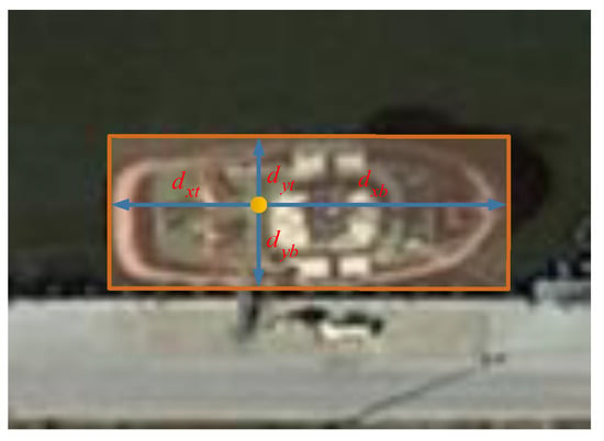
Figure 4.
The offset of the anchor-free detection branch. The distances from the current location to the left, right, top, and bottom side of the bounding box are represented by , , , and , respectively.
In order to normalize the offsets between objects of different sizes, the IoU loss is usually used for network optimization during training in anchor-free detection algorithms. The IoU loss is defined as follows:
where represents the IoU between the predicted box and the ground-truth bounding box. Since small ships in remote sensing images usually have unclear outlines, it is particularly important to accurately locate their center points. Therefore, a center point distance loss term is introduced to better locate the center point of the ship. The IoU loss with center point distance loss term is defined as follows:
where represents the square of the distance between the predicted box and the center point of the ground-truth bounding box, and c represents the diagonal length of the combined rectangle composed of the predicted box and the ground-truth bounding box, as shown in the Figure 5.
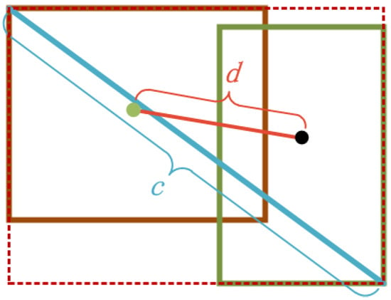
Figure 5.
Illustration of the center point distance.
Another important difference between the anchor-free branch and the anchor-based branch is the definition of positive and negative samples during training. The anchor-based branch needs to calculate the IoU between the anchor and ground-truth bounding boxes, and then compare it with the IoU threshold. However, IoU not only requires the location of the anchor to be accurate, but also needs to be similar in size to the ground-truth bounding boxes, which greatly limits the number of positive samples. In contrast, the anchor-free branch only needs to consider the geometric relationship between the current location and ground-truth bounding boxes, which can effectively increase the number of positive samples of small ship targets.
Specifically, for the anchor-free detection branch, a positive sample falls within the constraint rectangle. A constraint rectangle is a rectangular region with the same center point as the ground-truth bounding box, but 0.9 times its width and height. The constraint rectangle is set here to alleviate the imbalance offset regression when the pixel is too close to the boundary of the ground-truth bounding box. The samples between the constraint rectangle and the ground-truth bounding box are ignored, and the samples outside the ground-truth bounding box are negative samples. When adjacent ground-truth bounding boxes have overlap, the corresponding constraint rectangles may also overlap. For this case, the samples in the overlapped region will be matched to the closest ground-truth bounding box.
Since the output of anchor-based and anchor-free branches may highly overlap, it is necessary to eliminate redundancy through the non-maximum suppression (NMS) post-processing process and merge the prediction results of the two branches. The NMS algorithm ranks all proposals according to the classification scores, gradually eliminating the redundancy around the region with the highest scores. For the anchor-free branch and the anchor-based branch, the different definitions of positive and negative samples lead to different meanings of the classification scores of the two branches: the classification score of the anchor-free branch represents the probability that the current pixel location falls within the constraint rectangle, while the classification score of the anchor-based branch reflects the degree of overlap between the anchor and the ground-truth bounding box. Therefore, the classification scores of the two branches cannot be used in the NMS process.
In order to solve this problem and obtain the same output evaluation of the two branches, we proposes a label reassignment strategy that re-selects positive and negative samples according to the harmonic IoU before and after regression. The specific process of the label reassignment strategy is as follows:
- (1)
- The anchor-based and anchor-free detection branches first generate positive and negative samples according to their respective rules. Then, the IoU between these samples and the ground-truth bounding boxes is calculated, denoted as the a priori IoU, .
- (2)
- The two branches respectively perform location correction according to the output offsets to obtain ship proposals.
- (3)
- The IoU between proposals and the ground-truth bounding boxes is calculated, denoted as posterior IoU, . Then, and are weighted and summed to get the harmonic IoU:in which is the weighting coefficient.
- (4)
- The anchors and initial locations corresponding to the proposals with larger than 0.5 in the two detection branches are reselected as positive samples, while the regions where is less than 0.3 are negative samples. The rest are ignored.
In step (1), since the anchor-free branch does not have predefined anchors, each pixel location is regarded as a virtual anchor with the same width and height as the ground-truth bounding box to calculate the prior IoU of the anchor-free branch. The harmonic IoU adds the prior IoU before regression, which enhances the stability of the training. During training, we set to strengthen the effect of posterior IoU. After reassigning labels according to the harmonic IoU, the classification and regression losses are calculated according to the reselected positive and negative samples. At this time, the classification scores of the two branches both reflect the localization accuracy of the ship proposals, so that the outputs have unified evaluations. The classification scores are used for merging the output in the NMS post-processing process to obtain better detection results for each branch.
3.3. RoI Feature Super-Resolution
One of the important reasons why small ships are difficult to detect is the lack of detail information. Although the feature map at the bottom of the feature pyramid has relatively rich details, it still cannot make up for the missing information in the original image. A common method to solve this problem is to enlarge the image and supplement the missing details through image super-resolution technology to obtain high-resolution images. Since regular-sized ships and irrelevant background regions do not require sharper details, image super-resolution results in many unnecessary redundant computations. Taking high-resolution images as input significantly increases the computational burden of convolutional neural networks.
The idea of feature super-resolution is similar to image super-resolution, which reconstructs low-resolution features into high-resolution features with more detail information. Compared with image super-resolution, feature super-resolution is closer to object discrimination, which can maximize shared computing and reduce the computation cost. Therefore, we adopt feature super-resolution to obtain the super-resolution RoI features of the small ship proposals. Then, the second-stage classification and regression are performed on the basis of the super-resolution RoI features to obtain more accurate detection results.
3.3.1. High-Resolution Feature Extraction Network
Learning the super-resolution representation of low-resolution RoI features for small ships requires using the corresponding real high-resolution features as supervision. The high-resolution feature extraction network takes high-resolution images as input to obtain high-resolution output feature maps, and then the high-resolution RoI feature of small ships can be obtained through the RoI pooling operation. In order to have consistent correspondence between RoI features of different resolutions, the high-resolution RoI features must have the following properties: (1) The channel information is consistent with the low-resolution RoI features, so that the features have the same meaning. (2) The relative receptive field is consistent with the low-resolution RoI features, so that the features cover the same image region.
Directly using the backbone network as the high-resolution feature extraction network can ensure that the channel information is consistent, but it will lead to a mismatch in the relative receptive fields [43]. As the size of RoI decreases, the mismatch of the relative receptive field also increases. That is, low-resolution RoI features contain a wider range of information in the image, while high-resolution RoI features cover a smaller range, which causes the generated super-resolution features to lose part of the receptive field information and affects the subsequent detection results. Therefore, the high-resolution feature extraction network needs to enlarge the receptive field while maintaining parameter sharing with the backbone feature extraction network to reduce the mismatch of the relative receptive fields between RoI features. In our implementation, we replace all convolutional layers in the backbone feature extraction network with the corresponding convolutional layer in the high-resolution feature extraction network.
The high-resolution feature extraction network is only used during training and will be removed in the test phase. During training, the high-resolution and low-resolution images are fed into the high-resolution feature extraction network and the backbone feature extraction network, respectively, for parallel computation, and the multi-scale feature maps of the two images are obtained at the same time. According to the prediction result of the hybrid anchor detection structure, high-resolution RoI features are extracted from the high-resolution feature extraction network through the RoI pooling operation. The high-resolution RoI features are then serve as the supervision information for the feature super-resolution network.
3.3.2. Feature Super-Resolution Network
The feature super-resolution network maps low-resolution RoI features to super-resolution RoI features with more detail information. Since RoI features have a fixed spatial size, the output of the feature super-resolution network is the same size as the input feature. The high-resolution features contain low-resolution features and the missing high-frequency detail information. This correspondence can be described well by the residual structure. Therefore, we build the feature super-resolution network based on the residual module.
In general, deep networks have better image super-resolution performance. However, as the number of network layers increases, the number of parameters increases linearly, increasing the risk of overfitting, especially for the RoI feature, whose spatial size is usually only . Therefore, in order to better balance the network depth and the number of parameters, a recursive residual [44] module with parameter sharing is used to build the feature super-resolution network.
The structure of the recursive residual module is shown in Figure 6, in which the two consecutive size convolutional layers in the green dashed boxes are the basic convolutional units. To limit the growth of parameters, the parameters are fully shared between basic convolutional units. The recursive residual module consists of a basic convolution unit and a recursive residual structure, which recursively calls the basic convolution unit to calculate the residual output. Compared with an ordinary residual module, the recursive residual module increases the depth of the network without increasing the number of learnable parameters, so it has less risk of overfitting.
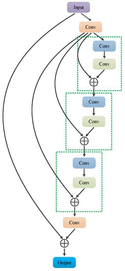
Figure 6.
Structure of the recursive residual module.
The feature super-resolution network composed of recursive residual modules is shown in Figure 7. The network consists of three recursive residual modules, and a dense connection structure is added between different residual modules to achieve feature reuse. The densely connected structure enables the input of each layer to fully absorb the outputs of all previous layers, so that the features extracted by different convolutional layers can be fully utilized to reconstruct high-resolution features.
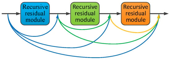
Figure 7.
Structure of the high-resolution feature generation network.
During training, the feature super-resolution network takes high-resolution RoI features output by the high-resolution feature extraction network as learning targets, and updates the network parameters through the feature super-resolution loss. In addition, in order to obtain more realistic super-resolutin features, the idea of a generative adversarial network is used to further optimize the output of the feature super-resolution network. Using the feature super-resolution network as the generator, the discriminator consists of two fully connected layers and a softmax layer to identify whether input features are real high-resolution features. After training, the discriminator is removed in the test phase. The super-resolution RoI features output by the feature super-resolution network are further subjected to second-stage classification and regression prediction to obtain the final detection results for small ships.
3.4. Training
3.4.1. Training Process
Most of the existing object detection methods only use single-resolution images in the training dataset to learn the feature representation of the object. Limited by the image resolution, for small objects, the features obtained by these methods are lacking in detail information, which is not conducive to accurate detection. In order to enrich the details of small ships, we design the feature super-resolution network to generate super-resolution features for the proposal of small ships. Training the feature super-resolution network requires real high-resolution features as supervision. Therefore, as shown in Figure 8, a parallel structure is used to train the network, generating low-resolution RoI features and the required high-resolution RoI feature at the same time.
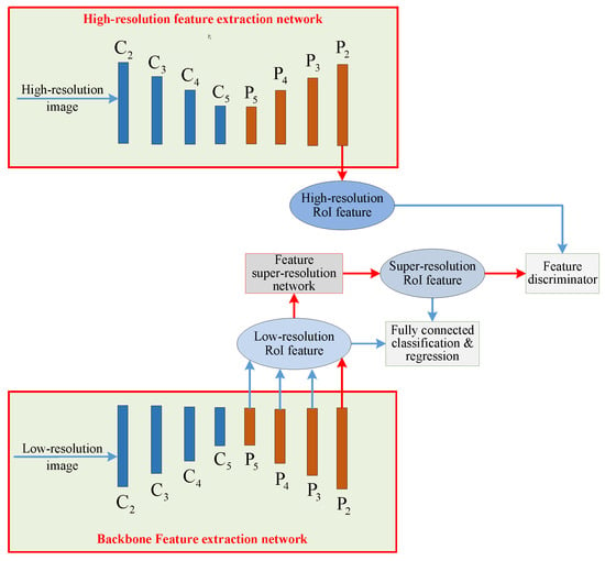
Figure 8.
The training pipeline of the proposed method.
During training, the backbone network takes low-resolution images as input. At different layers of the adaptive feature pyramid, the corresponding detection branches generate low-resolution ship RoI features of different sizes. Among them, the feature super-resolution network performs feature super-resolution on the RoI features of small ships generated by the detection branch located at the layer. Based on the super-resolution RoI features, the classification score and regression offset are predicted through the fully connected classification and regression layers. Besides small ships, ships of other sizes contain larger number of pixels, and sufficient detail information can be obtained from the original input image. Therefore, in order to reduce unnecessary computation, the RoI features generated by the detection branch located at the – layers are directly fed into the fully connected classification and regression layers for prediction.
Meanwhile, the high-resolution feature extraction network takes high-resolution images as input, and generates the corresponding high-resolution RoI features of small ships according to the output of the backbone network. The feature super-resolution network takes the generated high-resolution RoI features as the ground-truth, learning the mapping relationship between low-resolution features and real high-resolution features by optimizing the super-resolution loss. In addition, the feature discriminator discriminates super-resolution features from real high-resolution features during training, making the output of the feature super-resolution network more realistic.
In our implementation, the corresponding low-resolution image is obtained by down-sampling the high-resolution image. During training, the training image is directly used as the high-resolution image, and the image downsampled to half the size of the original image is used as the low-resolution image. The two images are input in pairs to the high-resolution feature extraction network and the backbone feature extraction network. The complete training process of the network is as follows:
- (1)
- The parameters of the high-resolution feature extraction network and the feature discriminator are fixed, while the backbone network and the fully connected classification and regression layers are trained.
- (2)
- The parameters of the backbone network are fixed, while the high-resolution feature generation network and the feature discriminator are alternately trained until they converge.
- (3)
- The parameters of all the remaining parts are fixed to exclude the influence of the generative adversarial loss, while the parameters of the fully connected classification and regression layers are fine-tuned to further improve the performance of the detection.
3.4.2. Loss Functions
The loss of the proposed method during training consists of three parts: the detection loss for training the detection model, the super-resolution loss for training the feature super-resolution network, and the discrimination loss for training the feature discriminator.
- (1)
- Detection loss
The detection loss consists of each detection branch of the adaptive feature pyramid and the classification and regression loss of the second stage. In order to facilitate convergence, the regression loss of all anchor-based detection branches in the – layers adopt the IoU loss shown in Equation (1). Both the anchor-based detection branch and anchor-free detection branch at the layer adopt the IoU loss with center point distance loss, as shown in Equation (2). The classification loss of each detection branch is consistent with [3]. The classification and regression losses of the second stage are exactly the same as the detection branches of the first stage.
- (2)
- Super-resolution loss
The super-resolution loss computes the deviation between the output of the high-resolution feature generation network and the real high-resolution feature pixel by pixel. It is defined as follows:
In Equation (4), subscript 2 means 2-norm, i is the serial number of the RoI feature, represents the low-resolution RoI feature, represents high-resolution RoI features, G represents the high-resolution feature generation network, and N is the number of samples.
- (3)
- Discrimination loss
The loss of the high-resolution feature discriminator is the categorical cross-entropy loss, which is defined as follows:
In Equation (5), represents the output probability for the feature discriminator, and is the category label for the i-th input feature ( for the real high-resolution feature, and for the generated super-resolution feature).
To sum up, the network loss L is equal to the sum of the above losses, as follows:
4. Experiments
4.1. Datasets and Implementation Details
The proposed method is verified on a remote sensing image dataset collected from Google Earth. The dataset contains a total of 3000 images, covering the port and sea environment. The dataset is randomly divided into a training set, validation set, and test set according to the ratio of 6:1:3. In order to more clearly show the detection performance on ships of different sizes, ships in the dataset are divided into three categories of small ships, medium ships, and large ships for evaluation. Among them, the size of the bounding box for small ships is less than pixels, while the medium ships are between pixels and pixels, and the large ships are larger than pixels.
The GPU model in our experiment is NVIDIA 1080Ti, the CPU model is Intel i7-7820X, and the memory is 32 GB. The experiment is carried out on the Ubuntu 16.04 operating system, based on the TensorFlow deep learning framework. The network is optimized by the Adam optimizer, with a total of 80,000 iterations. The learning rate is 0.001 for the first 40,000 iterations and 0.0001 for the second 40,000 iterations. Two images of different resolutions are input for the training in each iteration. The shorter side of the original image is scaled to 600 pixels to obtain the high-resolution input image. During training, the backbone network shares all learnable parameters with the high-resolution feature extraction network. During the test phase, the high-resolution feature extraction network and feature discriminator will be removed.
4.2. Experimental Analysis
4.2.1. Evaluation of the Adaptive Feature Pyramid
The adaptive feature pyramid improves the feature fusion of the original feature pyramid, and enhances the spatial information of deep features through information interaction. To verify the effectiveness of adaptive feature pyramid, Table 1 shows the evaluation results of different feature pyramid structures. In Table 1, SAP, MAP, and LAP represent the mean precision (AP) for small ships, medium ships, and large ships, respectively. The original feature pyramid adopts element-wise addition to fuse the adjacent two levels of features. In contrast, the convolution feature pyramid replaces the element-wise addition with a convolution operation after feature concatenation.

Table 1.
Evaluation results of different feature pyramid structures.
From the experimental results, we can see that although the convolution operation can learn the fusion weight, this weight does not bring obvious performance improvement. The adaptive feature pyramid predicts the fusion weight between different layers via the attention mechanism, so the AP of each kind of ship is effectively improved.
4.2.2. Evaluation of the Hybrid Anchor Structure
In this paper, an anchor-free detection branch is set in the hybrid anchor structure to detect small ships, and the training is further optimized with the help of a label reassignment strategy and center point distance IoU loss. For a more adequate comparison, a baseline model that does not contain the hybrid anchor structure is set as the benchmark for comparison. In the baseline model, the anchor-free detection branch is replaced by the anchor-based detection branch. Table 2 gives the evaluation results of the hybrid anchor box structure. Experimental results show that the anchor-free detection branch, the label reassignment strategy, and the center point distance IoU loss jointly improve the detection accuracy of small ships.

Table 2.
Evaluation results of the hybrid anchor structure.
4.2.3. Evaluation of RoI Feature Super-Resolution
In order to verify the effectiveness of the RoI feature super-resolution structure and its components, detailed comparative experiments are conducted on the receptive field matching of the high-resolution feature extraction network, as well as the recursive residual and densely connected structure of the feature super-resolution network. Experiment results are shown in Table 3. The receptive field matching can significantly improve the detection performance, which demonstrates the importance of maintaining similar receptive fields. In addition, recursive residuals and dense connections further boost the AP.

Table 3.
Evaluation results of the feature super-resolution network.
4.3. Comparison Results and Discussion
In order to further verify the effectiveness of the proposed method, the proposed method is compared with other three representative small object detection algorithms, which are the method from [40], the method from [45], and Libra R-CNN [46].
The method from [40] first performs the super-resolution operation on the features of the input image, and adds the super-resolution features to original features to obtain the features with enhanced details. Then, the enhanced features are used for detection. Method [45] first cuts out a suspected target region smaller than a certain size from the input image according to the detection results. Then, the captured image region is super-resolved to obtain the super-resolution image. Finally, the super-resolution images are classified as objects and non-objects to obtain the final result.
Libra R-CNN improves the small object detection performance based on two aspects of the training strategy and network structure. In the training strategy, the negative samples are uniformly extracted according to different IoU intervals to balance the number of positive and negative samples. For the network structure, the multi-scale features are first unified at intermediate size by interpolation and pooling for fusion, and then the original features are enhanced with the fused features.
The detection results of the different methods for small ships are shown in Figure 9. It can be seen that all three of the other methods have misdetections to some extent. For blurry pictures and unclear ships, the situation is even worse. In contrast, the proposed method combines a number of improved technologies, which effectively avoids misdetection and achieves the best detection performance for small ships.
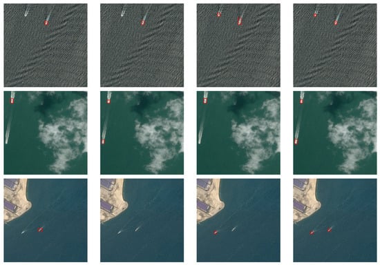
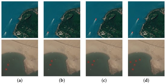
Figure 9.
Detection results of small ships with different algorithms: (a) method from [40]; (b) method from [45]; (c) Libra R-CNN; (d) our method.
Besides small ships, Figure 10 shows multi-scale ship detection results. Under the interference of complex port background, both the method from [40] and the method from [45] lost many warships and small ships. Libra R-CNN achieves better detection results than the above two methods by means of the improvements to the training strategy and network structure. However, some heavily disturbed ships failed to be accurately detected. In contrast, the proposed method can not only accurately locate small ships, but also has high detection accuracy for multi-scale ships.

Figure 10.
Multi-scale ship detection results of different algorithms: (a) method from [40]; (b) method from [45]; (c) Libra R-CNN; (d) our method.
Table 4 provides the quantitative evaluation results of different methods. It can be seen from the evaluation results that the proposed method has better detection performance than other methods on ships of various sizes, especially small-sized ships.

Table 4.
Evaluation results of different methods.
5. Conclusions
In this paper, we propose a small ship detection method based on hybrid anchor structure and feature super-resolution. Firstly, an adaptive feature pyramid is designed to enhance the information of important locations, and then the hybrid anchor structure is used to detect small ships based on the adaptive feature pyramid. The proposed structure combines the advantages of both anchor-based methods and anchor-free methods: an anchor-based detection branch is set to improve the localization accuracy, and an anchor-free detection branch is set to reduce misdetections. Then, a label reassignment strategy is proposed. During training, the sample labels are reset according to the harmonic IoU before and after regression. After label reassignment, the output evaluation of the two branches is unified to make better use of their complementary advantages. Finally, the feature super-resolution network is used to perform super-resolution reconstruction on the RoI features of small ships, and obtain more detailed super-resolution features for more accurate classification and regression. Detailed ablation and comparison experiments verify the effectiveness of the proposed method. Since the structure of the feature super-resolution part is slightly bloated, we consider using a more concise and efficient structure to achieve feature super-resolution to further improve the performance of the proposed method in our future work.
Author Contributions
Conceptualization, L.L.; methodology, L.L.; software, L.L.; validation, L.L. and X.X.; formal analysis, X.X.; investigation, Z.A. and G.L.; resources, X.X.; data curation, L.L.; writing—original draft preparation, L.L.; writing—review and editing, L.L. and Z.Z.; visualization, Z.A.; supervision, X.X.; project administration, L.L. All authors have read and agreed to the published version of the manuscript.
Funding
This research received no external funding.
Data Availability Statement
Not applicable.
Conflicts of Interest
The authors declare no conflict of interest.
References
- Girshick, R.; Donahue, J.; Darrell, T.; Malik, J. Rich feature hierarchies for accurate object detection and semantic segmentation. In Proceedings of the IEEE Conference on Computer Vision and Pattern Recognition, Columbus, OH, USA, 23–28 June 2014; pp. 580–587. [Google Scholar]
- Girshick, R. Fast r-cnn. In Proceedings of the IEEE International Conference on Computer Vision, Santiago, Chile, 7–13 December 2015; pp. 1440–1448. [Google Scholar]
- Ren, S.; He, K.; Girshick, R.; Sun, J. Faster R-CNN: Towards Real-Time Object Detection with Region Proposal Networks. IEEE Trans. Pattern Anal. Mach. Intell. 2017, 39, 1137–1149. [Google Scholar] [CrossRef] [PubMed] [Green Version]
- Dai, J.; Li, Y.; He, K.; Sun, J. R-fcn: Object detection via region-based fully convolutional networks. In Proceedings of the Advances in Neural Information Processing Systems, Barcelona, Spain, 5–10 December 2016; pp. 379–387. [Google Scholar]
- Liu, W.; Anguelov, D.; Erhan, D.; Szegedy, C.; Reed, S.; Fu, C.Y.; Berg, A.C. Ssd: Single shot multibox detector. In Proceedings of the European Conference on Computer Vision, Amsterdam, The Netherlands, 11–14 October 2016; Springer: Berlin/Heidelberg, Germany, 2016; pp. 21–37. [Google Scholar]
- Redmon, J.; Divvala, S.; Girshick, R.; Farhadi, A. You only look once: Unified, real-time object detection. In Proceedings of the IEEE Conference on Computer Vision and Pattern Recognition, Las Vegas, NV, USA, 27–30 June 2016; pp. 779–788. [Google Scholar]
- Dai, J.; Qi, H.; Xiong, Y.; Li, Y.; Zhang, G.; Hu, H.; Wei, Y. Deformable convolutional networks. In Proceedings of the IEEE International Conference on Computer Vision, Venice, Italy, 22–29 October 2017; pp. 764–773. [Google Scholar]
- Redmon, J.; Farhadi, A. YOLO9000: Better, faster, stronger. In Proceedings of the IEEE Conference on Computer Vision and Pattern Recognition, Honolulu, HI, USA, 21–26 July 2017; pp. 7263–7271. [Google Scholar]
- He, K.; Gkioxari, G.; Dollár, P.; Girshick, R. Mask r-cnn. In Proceedings of the IEEE International Conference on Computer Vision, Venice, Italy, 22–29 October 2017; pp. 2961–2969. [Google Scholar]
- Redmon, J.; Farhadi, A. Yolov3: An incremental improvement. arXiv 2018, arXiv:1804.02767. [Google Scholar]
- Liu, L.; Pan, Z.; Lei, B. Learning a rotation invariant detector with rotatable bounding box. arXiv 2017, arXiv:1711.09405. [Google Scholar]
- Lin, Z.; Ji, K.; Leng, X.; Kuang, G. Squeeze and excitation rank faster R-CNN for ship detection in SAR images. IEEE Geosci. Remote Sens. Lett. 2018, 16, 751–755. [Google Scholar] [CrossRef]
- Nie, S.; Jiang, Z.; Zhang, H.; Cai, B.; Yao, Y. Inshore ship detection based on mask R-CNN. In Proceedings of the IGARSS 2018-2018 IEEE International Geoscience and Remote Sensing Symposium, Valencia, Spain, 22–27 July 2018; pp. 693–696. [Google Scholar]
- Liu, W.; Ma, L.; Chen, H. Arbitrary-oriented ship detection framework in optical remote-sensing images. IEEE Geosci. Remote Sens. Lett. 2018, 15, 937–941. [Google Scholar] [CrossRef]
- Zhang, Z.; Guo, W.; Zhu, S.; Yu, W. Toward arbitrary-oriented ship detection with rotated region proposal and discrimination networks. IEEE Geosci. Remote Sens. Lett. 2018, 15, 1745–1749. [Google Scholar] [CrossRef]
- Yang, X.; Sun, H.; Fu, K.; Yang, J.; Sun, X.; Yan, M.; Guo, Z. Automatic ship detection in remote sensing images from google earth of complex scenes based on multiscale rotation dense feature pyramid networks. Remote Sens. 2018, 10, 132. [Google Scholar] [CrossRef] [Green Version]
- Zhang, Y.; Zhang, Y.; Shi, Z.; Zhang, J.; Wei, M. Rotationally unconstrained region proposals for ship target segmentation in optical remote sensing. IEEE Access 2019, 7, 87049–87058. [Google Scholar] [CrossRef]
- Li, Q.; Mou, L.; Liu, Q.; Wang, Y.; Zhu, X.X. HSF-Net: Multiscale deep feature embedding for ship detection in optical remote sensing imagery. IEEE Trans. Geosci. Remote Sens. 2018, 56, 7147–7161. [Google Scholar] [CrossRef]
- You, Y.; Cao, J.; Zhang, Y.; Liu, F.; Zhou, W. Nearshore ship detection on high-resolution remote sensing image via scene-mask R-CNN. IEEE Access 2019, 7, 128431–128444. [Google Scholar] [CrossRef]
- Ming, Q.; Miao, L.; Zhou, Z.; Dong, Y. CFC-Net: A critical feature capturing network for arbitrary-oriented object detection in remote-sensing images. IEEE Trans. Geosci. Remote Sens. 2021, 60, 1–14. [Google Scholar] [CrossRef]
- Ming, Q.; Miao, L.; Zhou, Z.; Song, J.; Yang, X. Sparse label assignment for oriented object detection in aerial images. Remote Sens. 2021, 13, 2664. [Google Scholar] [CrossRef]
- Lin, T.Y.; Dollár, P.; Girshick, R.; He, K.; Hariharan, B.; Belongie, S. Feature pyramid networks for object detection. In Proceedings of the IEEE Conference on Computer Vision and Pattern Recognition, Honolulu, Hawaii, 21–26 July 2017; pp. 2117–2125. [Google Scholar]
- Law, H.; Deng, J. Cornernet: Detecting objects as paired keypoints. In Proceedings of the European Conference on Computer Vision (ECCV), Munich, Germany, 8–14 September 2018; pp. 734–750. [Google Scholar]
- Zhou, X.; Wang, D.; Krähenbühl, P. Objects as points. arXiv 2019, arXiv:1904.07850. [Google Scholar]
- Chen, J.; Xie, F.; Lu, Y.; Jiang, Z. Finding arbitrary-oriented ships from remote sensing images using corner detection. IEEE Geosci. Remote Sens. Lett. 2019, 17, 1712–1716. [Google Scholar] [CrossRef]
- Zhang, Y.; Sheng, W.; Jiang, J.; Jing, N.; Wang, Q.; Mao, Z. Priority branches for ship detection in optical remote sensing images. Remote Sens. 2020, 12, 1196. [Google Scholar] [CrossRef] [Green Version]
- Chen, L.; Shi, W.; Deng, D. Improved YOLOv3 based on attention mechanism for fast and accurate ship detection in optical remote sensing images. Remote Sens. 2021, 13, 660. [Google Scholar] [CrossRef]
- Gao, F.; He, Y.; Wang, J.; Hussain, A.; Zhou, H. Anchor-free convolutional network with dense attention feature aggregation for ship detection in SAR images. Remote Sens. 2020, 12, 2619. [Google Scholar] [CrossRef]
- Dong, C.; Loy, C.C.; He, K.; Tang, X. Learning a deep convolutional network for image super-resolution. In Proceedings of the European Conference on Computer Vision, Zurich, Switzerland, 6–12 September 2014; Springer: Berlin/Heidelberg, Germany, 2014; pp. 184–199. [Google Scholar]
- Dong, C.; Loy, C.C.; He, K.; Tang, X. Image super-resolution using deep convolutional networks. IEEE Trans. Pattern Anal. Mach. Intell. 2015, 38, 295–307. [Google Scholar] [CrossRef] [PubMed] [Green Version]
- Dong, C.; Loy, C.C.; Tang, X. Accelerating the super-resolution convolutional neural network. In Proceedings of the European Conference on Computer Vision, Amsterdam, The Netherlands, 11–14 October 2016; Springer: Berlin/Heidelberg, Germany, 2016; pp. 391–407. [Google Scholar]
- Shi, W.; Caballero, J.; Huszár, F.; Totz, J.; Aitken, A.P.; Bishop, R.; Rueckert, D.; Wang, Z. Real-time single image and video super-resolution using an efficient sub-pixel convolutional neural network. In Proceedings of the IEEE Conference on Computer Vision and Pattern Recognition, Las Vegas, NV, USA, 27–30 June 2016; pp. 1874–1883. [Google Scholar]
- Kim, J.; Lee, J.K.; Lee, K.M. Accurate image super-resolution using very deep convolutional networks. In Proceedings of the IEEE Conference on Computer Vision and Pattern Recognition, Las Vegas, NV, USA, 27–30 June 2016; pp. 1646–1654. [Google Scholar]
- Ledig, C.; Theis, L.; Huszár, F.; Caballero, J.; Cunningham, A.; Acosta, A.; Aitken, A.; Tejani, A.; Totz, J.; Wang, Z.; et al. Photo-realistic single image super-resolution using a generative adversarial network. In Proceedings of the IEEE Conference on Computer Vision and Pattern Recognition, Honolulu, HI, USA, 21–26 July 2017; pp. 4681–4690. [Google Scholar]
- Zhang, Y.; Tian, Y.; Kong, Y.; Zhong, B.; Fu, Y. Residual dense network for image super-resolution. In Proceedings of the IEEE Conference on Computer Vision and Pattern Recognition, Salt Lake City, UT, USA, 18–23 June 2018; pp. 2472–2481. [Google Scholar]
- Haris, M.; Shakhnarovich, G.; Ukita, N. Deep back-projection networks for super-resolution. In Proceedings of the IEEE Conference on Computer Vision and Pattern Recognition, Salt Lake City, UT, USA, 18–23 June 2018; pp. 1664–1673. [Google Scholar]
- Dai, T.; Cai, J.; Zhang, Y.; Xia, S.T.; Zhang, L. Second-order attention network for single image super-resolution. In Proceedings of the IEEE/CVF Conference on Computer Vision and Pattern Recognition, Long Beach, CA, USA, 16–17 June 2019; pp. 11065–11074. [Google Scholar]
- Wang, B.; Lu, T.; Zhang, Y. Feature-driven super-resolution for object detection. In Proceedings of the 2020 5th International Conference on Control, Robotics and Cybernetics (CRC), Wuhan, China, 16–18 October 2020; pp. 211–215. [Google Scholar]
- Tan, W.; Yan, B.; Bare, B. Feature super-resolution: Make machine see more clearly. In Proceedings of the IEEE Conference on Computer Vision and Pattern Recognition, Salt Lake City, UT, USA, 18–23 June 2018; pp. 3994–4002. [Google Scholar]
- Li, J.; Liang, X.; Wei, Y.; Xu, T.; Feng, J.; Yan, S. Perceptual generative adversarial networks for small object detection. In Proceedings of the IEEE Conference on Computer Vision and Pattern Recognition, Honolulu, HI, USA, 21–26 July 2017; pp. 1222–1230. [Google Scholar]
- He, K.; Zhang, X.; Ren, S.; Sun, J. Deep residual learning for image recognition. In Proceedings of the IEEE Conference on Computer Vision and Pattern Recognition, Las Vegas, NV, USA, 27–30 June 2016; pp. 770–778. [Google Scholar]
- Li, L.; Zhou, Z.; Wang, B.; Miao, L.; Zong, H. A novel CNN-based method for accurate ship detection in HR optical remote sensing images via rotated bounding box. IEEE Trans. Geosci. Remote Sens. 2020, 59, 686–699. [Google Scholar] [CrossRef]
- Noh, J.; Bae, W.; Lee, W.; Seo, J.; Kim, G. Better to follow, follow to be better: Towards precise supervision of feature super-resolution for small object detection. In Proceedings of the IEEE/CVF International Conference on Computer Vision, Seoul, Korea, 27–28 October 2019; pp. 9725–9734. [Google Scholar]
- Tai, Y.; Yang, J.; Liu, X. Image super-resolution via deep recursive residual network. In Proceedings of the IEEE Conference on Computer Vision and Pattern Recognition, Honolulu, HI, USA, 21–26 July 2017; pp. 3147–3155. [Google Scholar]
- Bai, Y.; Zhang, Y.; Ding, M.; Ghanem, B. Finding tiny faces in the wild with generative adversarial network. In Proceedings of the IEEE Conference on Computer Vision and Pattern Recognition, Salt Lake City, UT, USA, 18–23 June 2018; pp. 21–30. [Google Scholar]
- Pang, J.; Chen, K.; Shi, J.; Feng, H.; Ouyang, W.; Lin, D. Libra r-cnn: Towards balanced learning for object detection. In Proceedings of the IEEE/CVF Conference on Computer Vision and Pattern Recognition, Long Beach, CA, USA, 15–20 June 2019; pp. 821–830. [Google Scholar]
Publisher’s Note: MDPI stays neutral with regard to jurisdictional claims in published maps and institutional affiliations. |
© 2022 by the authors. Licensee MDPI, Basel, Switzerland. This article is an open access article distributed under the terms and conditions of the Creative Commons Attribution (CC BY) license (https://creativecommons.org/licenses/by/4.0/).