Abstract
Non-precipitation echoes due to ground and sea clutter, chaff, anomalous propagation, biological targets, and interference in weather radar observations are major issues causing a decline in the accuracy of meteorological and hydrological applications based on radar data. Statistically based quality control techniques using polarimetric variables have improved the accuracy of radar echo classification, however their performance is affected by attenuation, nonuniform beam filling, and hydrometeor diversity as well as terrain blockage, beam broadening, and noise correction issues due to the quality degradation of polarimetric measurements. To address this, a new quality control algorithm, named clutter elimination algorithm for non-precipitation echo of radar data (CLEANER), was designed by employing independent feature parameters and variable classification conditions with spatial and temporal observation environments to adapt to these meteorological artifacts and observational limitations. CLEANER was applied to several precipitation cases with various non-precipitation echoes, showing improved performance compared with results from the fuzzy logic-based quality control algorithm in terms of non-precipitation echo removal as well as in precipitation echo conservation. In addition, CLEANER shows better computational efficiency and robustness, as well as an excellent expandability for different radar networks.
1. Introduction
Non-precipitation echoes (NPEs), such as ground and sea clutter (GC and SC, respectively), chaff (CF), biological target (BI), clutter by anomalous propagation (AP) and interference (IF) are frequently observed with precipitation echo (PRE); the intensity of NPE and its observed area tend to change depending on the surrounding environment in time and space in weather radar observations. These NPEs affect the accuracy of radar-based products for meteorological and hydrological applications, especially the accumulation rainfall amounts, depending on the performance of the quality control (QC) technique. Dual-polarization radar has led to remarkable achievements in terms of the classification of radar signals [1,2,3,4], as well as in microphysical and quantitative applications such as rainfall estimation [5,6,7] and data assimilation [8,9].
Most radar echo classification algorithms have been developed based on a probabilistic approach using supervised learning for polarimetric variables (reflectivity, ; differential reflectivity, ; differential phase shift, ; and correlation coefficient, ) and their spatial fluctuations to discriminate between PRE and NPE in real time [10,11,12,13]. These dynamic filtering algorithms using neural networks or fuzzy logic classification have shown generally good performance in the classification of a typical type of PRE and NPE. However, these statistically-based QC techniques may fail to identify severe NPE areas, such as GC overlapped with PRE, abnormal SC and AP, due to super refraction or ducting because of the distributions of their feature parameters for severe NPE do not partially follow that for usual NPE. Furthermore, the quality of polarimetric measurements changes over time due to beam blockage, attenuation, beam broadening with a range from radar, nonuniform beam filling (NBF), hydrometeor diversity within a sample volume, and noise correction issues at low signal-to-noise ratio (SNR) [14,15,16,17,18]. These statistical properties of polarimetric variables and physical limitations of radar observation may finally result in the performance degradation of statistically based QC techniques. Ref. [19] developed a physically-based QC scheme based on meteorological principles using , and atmospheric thermodynamic fields to conserve atypical PRE, which showed a better skill score than that of the neural network QC algorithm.
This study aims to develop an operational QC algorithm for South Korean weather radar networks that is minimally affected by the quality of polarimetric variables, observational properties and environment. The new QC technique was named clutter elimination algorithm for non-precipitation echo of radar data (CLEANER), which has several dynamic filters designed by considering various radar artifacts to improve the classification performance between severe NPE and atypical PRE. Section 2 introduces the concept and characteristics of CLEANER with operational radar networks. The methodology is described in Section 3, and CLEANER is compared with the fuzzy logic-based QC (FQC) algorithm in Section 4. Conclusions and remarks are summarized in Section 5.
2. CLEANER
Weather radar observations in Korea are significantly contaminated by GC, SC and CF, and affected by beam blockage and seasonal variation in the hydrometeor because the Korean peninsula, located in the middle latitudes, has mountainous terrain up to 70% (Figure 1) and frequent air force flight training. In addition, AP by super refraction and ducting at coastal radar sites are frequently caused by the inflow of moist air from the sea and large daily temperature changes [20] that often remain even after applying a statistically based QC algorithm. The weather radar center (WRC) of the Korea meteorological administration (KMA) has operated ten Doppler weather radars, which were all upgraded to dual-polarization radar from 2014 to 2019. The volume scan (VCP), with nine elevation angles, and a long-range scan (LNG) with one low-elevation angle, are performed every 5 min with the radar observation characteristics listed in Table 1. As the other three departments of the Korean government have operated their own polarimetric radars with different observation characteristics for different purposes (e.g., five S-band by the flood control office, six C-band by the Air Force and one C-band by the Navy), WRC has made efforts to provide high-quality weather information from polarimetric radars by developing QC techniques that can encompass all the different radar networks.
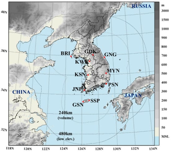
Figure 1.
S-band operational radar network of Korea meteorological administration (KMA). Coverages indicate the observation areas for volume and long-range scans; red marks represent the KMA radar sites.

Table 1.
Characteristics of the S-band dual-polarization radars operated by the KMA.
CLEANER, which began to be developed as a sweep-based radar QC algorithm in 2017, has been continuously improved to classify all types of NPEs from PREs that are reflected from all types of precipitation particles more clearly, even if the PRE is affected by a melting layer or nonuniform beam filling, except for range-folding echo. CLEANER has been applied to the operational system of the Korean weather radar networks since 2019. The followings are the characteristics of CLEANER: (1) employs new feature parameters that has different properties with generally-used feature parameters based on statistical characteristics; (2) basically applies individual classification conditions and constraints for each feature parameter; and (3) customizes each condition spatially and temporally in real time by considering the quality of polarimetric variables, observational properties and environment. New feature parameters were based on meteorological characteristics between polarimetric variables, and each classification condition; constraints were determined to minimize misidentification for PRE. For the development of CLEANER, Korean operational radar data collected from 2016 to 2020 were analyzed to comprehend the meteorological and observational characteristics of polarimetric variables for PRE and NPE that were distinguished using polarimetric observations and their statistical quality, clustered-echo shapes, moving tendency of the echo, vertical structure of the echo and comparisons with other radar data, surface observations, and satellite data at the same time.
CLEANER consists of four main processes applied sequentially for real-time operation and two sub-steps to automatically reproduce the GC static map and beam blockage mask with a renewed radar scan strategy (Figure 2). The main procedure includes (1) the identification of GC using traditional radar moments (unfiltered reflectivity, ; clutter-filtered reflectivity, ; and radial velocity, ), (2) real-time offset determination and unfolding of , (3) classification of NPE and (4) residual NPE removal. This sequential flow considers the state of Korean operational radar data, in which the dual-polarization measurements in GC areas are mostly lost by a clutter filter in signal processing (except for KMA radar systems after April 2020), especially when there is no PRE. The sub-steps provide a static GC map and simulated beam blockage fraction (PBB) corresponding to each radar scan strategy, which are used as feature parameter and correction factors in the first and third steps of the main procedure, respectively. The details of the CLEANER methodology are described in Section 3.
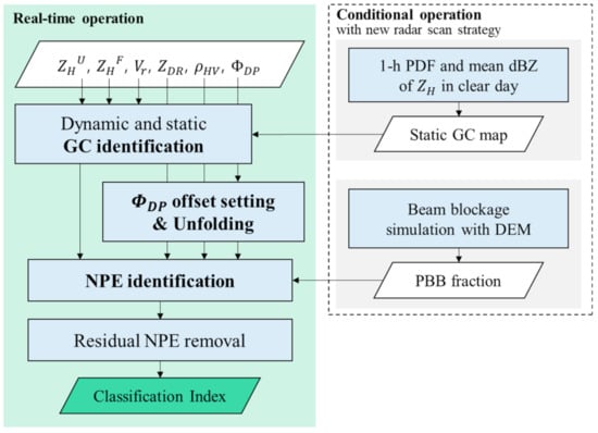
Figure 2.
Flowchart of clutter elimination algorithm for non-precipitation echo of radar data (CLEANER) with the four main processes and two sub-processes.
3. Methods
3.1. Identification of Ground Clutters
GCs returned from surface targets, such as mountains, bridges and ships, have mostly high reflectivity, which rapidly decreases at its boundary. GCs can be suppressed by clutter filters, such as the infinite impulse response (IIR) or Gaussian model adaptive processing (GMAP) filters in signal processing but may be partially retained when they have a radial velocity due to moving targets (e.g., vegetation, ships and vehicles). Furthermore, GC overlapping with PRE above a moderate rainfall rate is difficult to suppress completely by a clutter filter; these filters weaken the intensity of PRE signals and make polarimetric measurements abnormal in an area with near-zero Doppler velocity. These misclassifications cause significant errors in the quantitative precipitation estimation, especially in accumulative rainfall.
Generally, techniques to detect GC using radar moments use static GC maps or dynamic feature parameters. The static map can correctly implement the usual GC area, but cannot respond to the variations in the clutter areas and their intensity due to super refraction or the renewal of radar scan strategy. The dynamic feature parameters are more adaptive for identifying the GC. However, the radial texture () (i.e., the standard deviation within a given range interval in a radial direction) of the polarimetric variables generally used in GC identification has lower performance in the center of larger-clustered clutter than that of the range interval of and weak GC with low spatial fluctuation; it may also misidentify some PRE in contact with GC or in the boundary of a strong convective storm. Hence, this study designed a new GC identification module using , , and for optimization with the Korean radar systems, even for a single polarization Doppler radar system. The GC identification module defined new feature parameters and merged dynamic and static identification techniques to complement the weaknesses of each technique for operational applications.
3.1.1. Feature Parameters for Ground Clutter
New dynamic feature parameters were developed based on the effects due to clutter filtering and the “towering” shape of GC with higher reflectivity than that of the surroundings () in the field. Herein, is defined as the difference between and the , and and are defined as the deviation with lower reflectivity within a given range interval and as the difference between s of and , respectively, as follows:
where and indicate the index number in each radial, and changes within a given range interval that decrease from 10 to 3 km with the elevation angle to consider the range scale of GC clusters. is calculated with a tolerance of 5 dB to consider a statistical fluctuation and is the number of available data within the range interval. In addition, with a 2 km range interval is used to identify small-scale clutters, such as ships and bridges.
The static GC map is an assistive feature parameter for larger-clustered GC than the range interval of or low-reflectivity GC that is indistinguishable in the dynamic feature parameters. The static map is defined with two fields: GC detection frequency () and GC mean reflectivity (). These are constructed using observations for greater reflectivity than 20 dBZ during an hour on a clear day and reproduced when the radar scan strategy (i.e., elevation angles or spatial resolution) is changed. This short counting time interval enables the rapid updating of the static map in response to the renewal of the scan strategy in operation. Herein, the clear day is the day when there are few echoes, except for GC, and it is discernible with few echoes in the field.
3.1.2. Characteristics of the Feature Parameters and Identification for Ground Clutter
Figure 3 shows an example of , , and and the feature parameters for GC identification for the super refraction case accompanied by PRE from the west. -based parameters are effective in the GC boundary and a smaller size clutter than the range interval of ; these are ineffective in the center of bigger clustered-clutter than the range interval of (yellow box in Figure 3) and weak GC with a low spatial fluctuation and low Doppler filter effect (white box in Figure 3). is a good classifier in stationary GC with no or weak precipitation regardless of the spatial size of GC, which may incorrectly identify some precipitation areas near zero as clutter (purple box in Figure 3). works well in most GC regardless of intensity; however, it cannot identify GC by super refraction in the far range (red box in Figure 3).
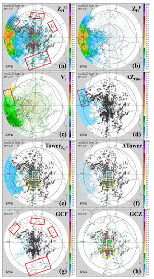
Figure 3.
(a–c) Observed reflectivity and radial velocity and (d–h) corresponding feature parameters of CLEANER for ground clutters of KWK observations at 0600 local standard time (LST) 2 June 2020. Red, purple, white, and yellow boxes indicate ground clutter (GC) due to super refraction, zero isodop, weak GC, and large-clustered GC, respectively.
GC echoes are dynamically identified from PRE or other NPE if any of the feature parameters independently exceeds each threshold value in Table 2 to compensate for the weakness of each feature parameter. Each threshold value was empirically determined to a level that minimizes the misidentification for PRE. The static GC map (Figure 3g,h) specifies regular GC areas when exceeds 90%, and adaptively identifies GC echoes using the threshold value adjusted by the difference between and at a low elevation angle () and low altitude (). This adaptive condition for the static map can identify large-clustered GC areas from no or weaker PRE, and does not classify weak GC when strong PRE is overlapped.

Table 2.
Feature parameters and identification conditions for ground clutter.
3.2. Processes for Differential Phase Shift
3.2.1. Offset Determination in Real Time
The offset of can be changed by a radar system check for maintenance. System maintenance is usually performed on clear days, such that it is difficult to properly set the offset of () for PRE. In addition, the offset value often changes after initially observing the precipitation echo by radar operators when setting an improperly high or low offset. Thus, real-time determination is required prior to the quantitative use of measurements.
This study initially determined the of each volume scan from the continuous PRE area. The is calculated by averaging the offset values of each elevation angle. The offset values of each elevation angle are calculated by averaging the values extracted from radially continuous PRE. Here, the continuous PRE is determined with high and low values from polarimetric variables before meeting the convective cell (>35 dBZ) within a 20 km range of the PRE path for each radial. If a continuous PRE area does not exist, the is extracted. Second, from the AP echo area that has soft spatial textures of polarimetric fields, we searched for a minimum value of the averaged values within a 20 km range interval at elevations lower than 2.5°. The AP area is limited with the following conditions to exclude other NPEs such as SC, BI, CF, and interference: (1) 0 < < 30 dBZ; (2) || > 5 ms−1; (3) 0 < < 5.0 dB; (4) 0.5 < < 0.92; (5) < 30°; (6) < 4 dB; and (7) < 0.3. This study defined of the polarimetric variable () as the radial root mean square differences. s of the polarimetric variables are calculated as follows:
where and indicate the index number in each radial, changes within a given range interval and is the number of available data within the range interval. The range intervals adaptively increased up to 1.75 km with increasing reflectivity (minimum is 3 gates) to reduce NPE-neighboring contamination because weaker precipitation echoes have a higher probability of contact with NPE and vice versa.
Figure 4 shows the time series of the ΦDP offset and the areal ratio of the PRE and NPE. The offset from PRE is highly stable (red line in Figure 4) whereas the offset from NPE (yellow line in Figure 4) is similar to that from PRE. Herein, numerous far-range GCs were detected accompanying high AP areal ratios and gradually decreased as precipitation approached the radar site. This indicates that the detection number of a far-range GC can provide some guidelines for the AP-dominant observation situation.
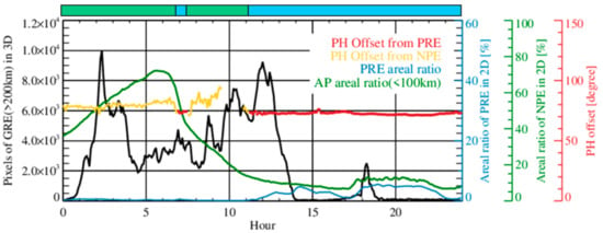
Figure 4.
Time series of the offset value of differential phase calculated from the precipitation echo (red line, blue shaded period) and non-precipitation echo (yellow line, green-shaded period), as observed by the BRI at the lowest elevation angle on 12 March 2020. Blue and green lines indicate the areal ratio of precipitation echo (PRE) and non-precipitation echoes (NPE), respectively.
3.2.2. Unfolding for Multi- and Inverse-Folding
The measurements were produced from 0° to 360° (or 180° with data-stored resolution) as phase-based variables. When strong convective cells lie in radial directions, the rapidly increases over 360°, and the folding occurs, even in S-band radar (Figure 5a). In contrast, when the offset value is near zero, folding occurs inversely in the boundary of the PRE (Figure 5c).
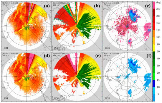
Figure 5.
Differential phase (a–c) before and (d–f) after unfolding for three-folding cases; single folding in S-band BRI radar at an elevation angle of 0.2° at 1020 LST 13 May 2017 (left), multi-folding in C-band radar at an elevation angle of 1.4° at 2300 LST 2 October 2019 (middle) in precipitation cases and inverse folding by near-zero offset in the S-band GDK radar at an elevation angle of −0.4° at 1505 LST 26 December 2019 (right).
The unfolding technique that uses the radial texture of as a folding determinant parameter may be miscalculated in the area where folding and unfolding occurs alternately. This study developed an unfolding technique based on the difference between the observed () and reference () by following seven steps with each radial. The is the of the prePRE bin, where the PRE bin is updated during each radial unfolding using random error () within a 1.5 km range interval.
- We set the maximal-valid increment considering the maximal specific differential phase shift with radar wavelength and also set the valid fluctuation amount every bin with data quality affected by the wavelength and total-valid difference () due to PRE.
- Set initial to
- Add the folding amount () to if the difference between and () is smaller than–75% of
- Subtract to if is larger than 75% of
- Save step 3 or 4 as unfolded () if the absolute value of the difference between and () is smaller than
- Update with the averaged value between and processed by unfolding if the bin is PRE according to the following conditions: (i) larger than and ; (ii) difference between and is larger than –50% of and smaller than (valid increment ); and (iii) is smaller than the valid variation.
- Repeat step 3 times until is smaller than 75% of () to unfold the multi-folding (for a C- or X-band radar system).
Figure 5d–f shows the fields after applying the unfolding procedure developed in this study. The left panel shows the folding case due to the convective precipitation system with hail in the S-band radar, middle panel shows the multi-folding three times in the C-band radar, and right panel shows the inverse-folding due to near-zero offset in the winter season. All types of folding were completely unfolded, and this unfolding algorithm showed a 99% success rate for S-, C- and X-band radar systems in long-term applications. Through this unfolding, the can be used to classify NPE as a feature parameter both quantitatively and statistically.
3.3. Classification of Precipitation and Non-Precipitation Echoes
Figure 6a–f (and Figure 5d) show an example of polarimetric measurements and their s of a precipitation case with hail and NBF. The hail particles with low values of and were present near the radar site and NBF area with low values of and ; high s for the polarimetric variables were observed along with the hail and convective cells at 10–15° azimuthal direction, yielding in folding. The hydrometeors changed to snow and ice crystals above a height of 2.5 km (approximately 180 km range). SC was observed within a 40 km range, and weak AP were also observed over 90–300° azimuthal directions. The SC is well identified from PRE in polarimetric fields, but some AP areas in the south direction are difficult with respect to classification from PRE because the s and values in the AP area are not different from hail, NBF and ice crystals.
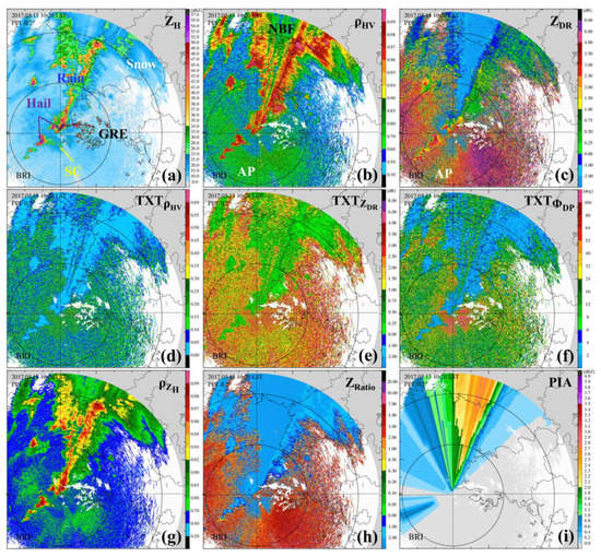
Figure 6.
Polarimetric observations of (a) , (b) , and (c) and (d–f) the generally-used feature parameters of radial texture of , and, (g–i) new feature parameters of CLEANER for the classification of non-precipitation echo from the BRI observations at 1020 LST 13 May 2017.
This study defined new feature parameters based on the consistency between polarimetric variables, considering their meteorological distributions, which were used to completely classify PRE-NPE with s and . This Section describes the feature parameters, their characteristics and classification conditions for NPE. The observed was corrected with wet-radome attenuation for each elevation angle as reported in [21], partial beam blockage fraction () simulated with a digital elevation model (DEM), and path-integrated attenuation () estimated PRE-NPE classification from as reported in [22].
3.3.1. Set of Maximum Reflectivity for Non-Precipitation Echo
NPEs, especially AP, which is difficult to classify from PRE, are strongly observed at low observational elevation angles. Figure 7 shows the two different distributions of the maximum-observed reflectivity at each elevation angle () after GC removal for mostly strong AP and hail-PRE cases. In contrast to the PRE case with hail, the maximum reflectivity over 70 dBZ at low elevation in the strong AP case due to ducting rapidly decreases to 30 dBZ with an increasing elevation angle. Therefore, setting the maximum reflectivity of the NPEs () is effective in preventing the misclassification of the PREs, especially with an increase in the observational elevation angle. The can be applied as a function of or as a table of discontinuous values for each . CLEANER empirically sets as a function of (dashed line in Figure 7) as follows:
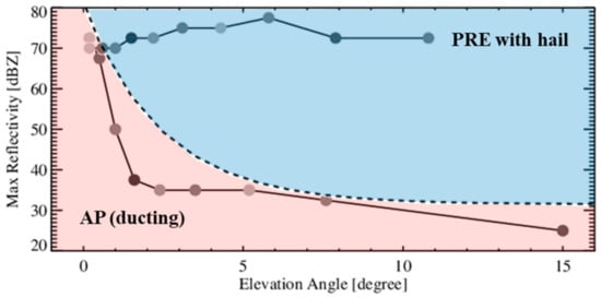
Figure 7.
Observed maximum reflectivity with each elevation angle for a strong convective system and severe anomalous propagation case, The red shaded area indicates the reflectivity range with observational elevation angles for AP whereas the blue shaded area indicates the reflectivity range that can be excluded from NPE classification when the maximum reflectivity with observational elevation angles is applied as the dashed line.
This excludes the possibility of misidentification of the BB and hail area at high elevation angles (blue shaded area in Figure 7).
3.3.2. Feature Parameters and Their Characteristics for Non-Precipitation Echo
The radial s of the polarimetric variables within a specific range interval (e.g., usually 1–2 km) have good performance for SC and CF because they mostly have high spatial fluctuations within the range interval of the . However, s may have low performance in strong SC by ducting where the spatial size of the fluctuation is valid on a larger spatial scale than the range interval of the ; in the precipitation boundary, they may be contaminated by the fluctuations of neighboring NPEs as the range interval is larger. In this section, of the polarimetric variable () is calculated using equation (5).
As the quality of data also becomes worse in hail, NBF and BB similar to the s of polarimetric variables, can safely classify only weak NPE (Figure 6b). Therefore, a constant threshold value for may cause incorrect PRE-NPE classification. CLEANER defined a reflectivity-weighted coefficient () by converting the observed to a value from 0 to 1 using a convergent function as follows:
where for is corrected, and the observed is used as a weighting factor. Herein, the increment of 30 dBZ for considers a negative dBZ and is 20.0 ( can reach 0.993 when is 5 T). This function is similar to the - distribution of precipitation echoes collected from Korean radar data that has the noise correction issue at low SNR [18]. The low threshold value for can remove only weak NPE with low and low , while preserving atypical PREs (see Figure 6g).
is not a general classification parameter because the range of for NPE is very wide, ranging from –8 to 8 dB, which covers the range of PRE. Figure 6c shows that both PRE with big-drop and BI are high, and both NBF and SC are small (negative) values. The high of NPE with weak is outside of the – distribution for raindrops, which is a proportional relation, as confirmed by scattering simulation and radar measurements. Thus, this study defined the ratio between one-tenth of and () at a linear scale as a feature parameter for weak AP and BI, as follows:
Figure 6h shows the in a field that is mostly higher than 3.0 in NPE. Herein, the system bias of can properly be adjusted by the – mean relation from the drop size distribution data within the weak rain in real time.
can effectively segregate NPE, especially AP and the interference echo, from PRE when is small because has a valid increment with the range due to only PRE. For example, in Figure 5d and Figure 6i, the offset value of was calculated approximately 75° based on Section 3.2.2; the reflectivity-based was bigger than 1.0 dB only in the north direction. This indicates that the large increment from the offset value is invalid except in the north direction just at that time. Thus, the difference between the observed and its offset value () can be used as a new feature parameter compared with reflectivity-based :
3.3.3. Classification Conditions for Non-Precipitation Echo
The quality of polarimetric measurements is low when the correlation between hydrometeors within the radar sample volume decreases. In other words, the spatial fluctuations of polarimetric variables for mixed targets such as hail, wet snow and ice crystals, are high with reduction. This quality degradation is also related to NBF, beam broadening with range, and noise correction issues at low SNR [14,15,16,17,18]. Furthermore, NPE is observed frequently and intensely at low elevations; thus, changeable classification conditions with an increasing observation range and height are more effective for NPE removal and PRE conservation than unchangeable conditions. Similar to the concept of the GC identification module in Section 3.1, NPEs, except for GC echo, are classified from PRE if any of the feature parameters except for and , independently exceeds each threshold value with its adjustment in Table 3. In contrast, and work when they fail to reach each threshold value. The threshold values are adjusted with the , observation range () and height (), observational elevation angle () and maximum range () of the radar scan, and seasonal echo top height ( varying from 3 to 12 km) to consider beam broadening and vertical distribution of the hydrometeor. The constraints determine a boundary such that each feature parameter can work for every observation point with (not described in Table 3, but applied, except for –related classification conditions) to conserve PREs in NBF, attenuated areas, and the melting layer. The initial threshold values were also empirically determined to be sufficient to preserve atypical PREs such as hail, NBF, BB and ice crystals. In addition, when severe AP due to super refraction or beam ducting occurs, some threshold values can be adjusted more strictly with the NPE areal ratio near the radar site and the detection ratio of far-range GC to completely remove indistinguishable AP echoes.

Table 3.
Feature parameters and classification conditions for non-precipitation echoes.
4. Results
This section describes the results of NPE removal for various types of radar echoes through CLEANER by comparison with the FQC. The FQC algorithm was developed in 2015 using TXTs of polarimetric variables, , and as the feature parameters as following [23] with the optimization process for each radar dataset.
4.1. Ground Clutters
Figure 8 shows two cases of for the static GC map and 1-h mean reflectivity with large-clustered clutter within 100 km range and far-range clutter due to super refraction, respectively. In this comparison, the FQC worked for all types of NPE and CLEANER only applied the GC identification step (the GC area is filled with filtered reflectivity with low of ). The FQC failed to identify some GC areas overlapped with PRE (red lines in Figure 8) or weak GC near the radar site (black lines in Figure 8). The remaining GC in Figure 8c,g causes the overestimation in rainfall estimation. The dynamic and static identification of CLEANER completely identified large-clustered clutters, far range GC by super refraction, and even weak GC near the radar site (Figure 8d,h).
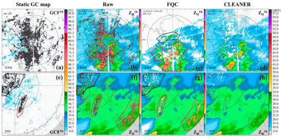
Figure 8.
(a,e) The static GC map () and 1-h mean reflectivity fields before and after applying quality control (QC) algorithms. (b–d) The case with large-clustered GC of KWK at an elevation angle of –0.2° from 1100 to 1155 LST 27 August 2020. (f–h) Super-refraction case of PSN at an elevation angle of 0.1° from 1500 to 1555 LST 23 April 2019.
4.2. Anomalous Propagations
Figure 9 shows two different types of severe AP cases with ducting (top) and super refraction (middle and bottom). The FQC identified the GC even over the 200 km range. However, notably, the FQC left NPE by ship and AP echo because polarimetric variables had soft spatial textures or the was not low enough to be classified as NPE (not shown here). CLEANER separated most of the AP from the PRE, which was mainly effective using invalid increments and applying additional classification conditions that are enhanced with the PRE/NPE areal ratio or the detection number of far-range GCs over 200 km.
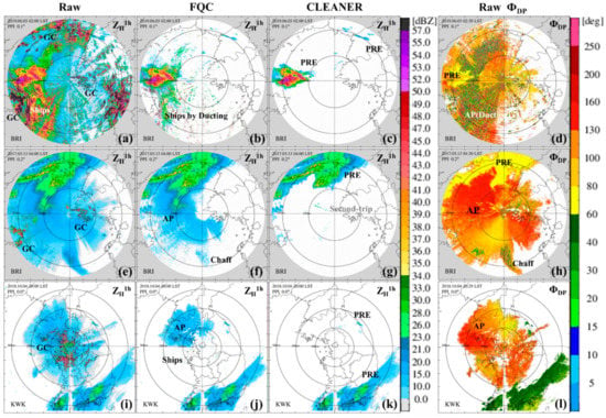
Figure 9.
As in Figure 8, but with the differential phase field for the anomalous propagation cases with PRE (a–d) in ducting collected by BRI at an elevation angle of 0.1° from 0200 to 0255 LST 3 June 2019 (top), in super refraction collected (e–h) by BRI at an elevation angle of 0.2° from 0400 to 0455 LST 13 May 2017 (middle), and (i–l) by KWK at an elevation angle of 0.0° from 2000 to 2055 LST 4 October 2020 (bottom).
4.3. Hail and Nonuniform Beam Filling
When hail or graupel particles exist in the radar sample volume, can be decreased to approximately 0.8, and the s of polarimetric variables can be increased in the hail boundary (Figure 10d). In Figure 10c, CLEANER correctly preserved the hail area and removed SC and AP while the FQC misidentified the hail and their boundaries and retained some AP echoes (Figure 10b).
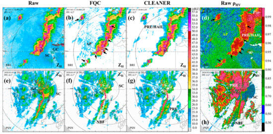
Figure 10.
Reflectivity fields (a,e) before and after applying (b,f) the FQC algorithm and (c,g) CLEANER, and (d,h) correlation coefficient fields for hail (top) and non-uniform beam filling (bottom) cases collected by BRI at an elevation angle of 0.2° at 1000 LST 13 May 2017 and by PSN at an elevation angle of –0.1° for a 480 km observational range at 2124 LST 7 January 2020, respectively.
NBF with quality degradation of the polarimetric fields is commonly observed when convective storms are lined up with the long radial direction and/or sampled with a relatively large beam width. This study separates the NBF area with reflectivity-based (because NBF is associated with high-reflectivity PRE) and applies relaxed classification conditions to the NBF area rather than to other areas. The high direction was consistent with the NBF and large area; CLEANER mostly conserved the PRE in the NBF area, in contrast to the FQC results (Figure 10f,g).
4.4. Bright Band, Snow and Ice Crystals
Figure 11 shows prominent BB cases of low and high elevation angles for different seasons and a snow case in a coastal area. CLEANER mostly conserved the BB area and even ice crystals using a variable threshold value with the beam height and seasonal echo top height, contrary to the FQC results. Ice crystals are usually observed with a high value, low value and high spatial fluctuation in the polarimetric measurements to a level similar to NPE, especially the field. CLEANER excepted or relaxed the -related classification conditions for the winter season (December, January and February) to classify ice crystals as PRE more correctly.
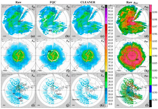
Figure 11.
As in Figure 10, but with the correlation coefficient field for two bright band cases collected (a–d) by GSN at an elevation angle of 0.2° at 0700 LST 16 December 2018 and (e–h) by KWK at an elevation angle of 7.3° at 1100 LST 1 July 2018 and (i–l) a snow case collected by JNI at an elevation angle of −0.1° at 0600 LST 12 February 2018.
4.5. Applications to C- and X-band Polarimetric Radars
CLEANER was designed to overcome the quality degradation of polarimetric measurements due to meteorological and observational properties through physically-based feature parameters and adaptive classification conditions to various error factors, such as beam blockage, attenuation, beam broadening, hydrometeor and NBF in real time. Thus, this new QC algorithm can be applied to other radar systems of shorter wavelengths, i.e., C- or X-band, because they have similar meteorological and observational properties in polarimetric measurements for PRE and NPE as the S-band radar. In particular, more rapidly increases for shorter wavelength, but is still available in C- and X-band because used as adjustment or constraint factor also increases larger than S-band radar by applying a proper - relation for each radar wavelength. Figure 12 is the result for the C-band polarimetric radar of the air force and for the X-band polarimetric radar of KMA for research. In both cases, large increments were observed with polarimetric quality degradations due to BB and attenuation. CLEANER effectively classified GC and IF from PRE without additional optimization.
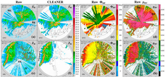
Figure 12.
Reflectivity fields (a,e) before and (b,f) after applying CLEANER with (c,g) raw differential phase and (d,h) correlation coefficient fields collected by C-band polarimetric radar of KWJ of the air force an elevation angle of 2.0° at 1400 LST 7 August 2020 (top) and by KMA X-band radar for research an elevation angle of 0.8° at 1400 LST 2 August 2020 (bottom), respectively.
5. Conclusions
CLEANER is a new quality control algorithm designed to effectively separate all types of NPEs (except range-folding echo) from PRE for operational radar systems in Korea. The new feature parameters were based on the characteristics of ground clutter in the reflectivity field and meteorological consistency between polarimetric variables, and each parameter with different characteristics effectively classified a specific NPE. The classification conditions for each parameter independently worked and flexibly changed to consider meteorological artifacts such as NBF, attenuation and hydrometeor type and observational limitations such as terrain blockage, beam broadening, abnormal refraction and noise correction issues with low SNR.
The results of NPE removal by CLEANER showed better performance in various PRE and NPE cases than the results from the fuzzy logic-based algorithm in terms of both NPE removal and PRE conservation. The datasets collected by other radar networks with different radar wavelengths and scan strategies were also successfully processed by CLEANER without additional data training and optimizations, and the computation efficiency of CLEANER for real-time operation was improved compared with the fuzzy logic-based algorithm.
Author Contributions
Conceptualization, Y.-A.O.; methodology, Y.-A.O.; software, Y.-A.O.; validation, Y.-A.O.; formal analysis, Y.-A.O.; investigation, Y.-A.O., H.-L.K. and M.-K.S.; writing—original draft preparation, Y.-A.O.; writing—review and editing, Y.-A.O., H.-L.K. and M.-K.S.; visualization, Y.-A.O.; supervision, H.-L.K. and M.-K.S.; funding acquisition, H.-L.K. and M.-K.S. All authors have read and agreed to the published version of the manuscript.
Funding
This study was supported by the “Development and application of cross governmental dual-pol radar harmonization (WRC-2013-A-1)” project of the Weather Radar Center, Korea Meteorological Administration.
Conflicts of Interest
The authors declare no conflict of interest.
References
- Vivekanandan, J.; Zrnić, D.S.; Ellis, S.M.; Oye, R.; Ryzhkov, A.V.; Straka, J. Cloud microphysics retrieval using S-band dual-polarization radar measurements. Bull. Amer. Meteor. Soc. 1999, 80, 381–388. [Google Scholar] [CrossRef]
- Rico-Ramirez, M.A.; Cluckie, I.D. Classification of ground clutter and anomalous propagation using dual-polarization weather radar. IEEE Trans. Geosci. Remote Sens. 2008, 46, 1892–1904. [Google Scholar] [CrossRef]
- Thompson, E.J.; Rutledge, S.A.; Dolan, B.; Chandrasekar, V.; Cheong, B.-L. A dual-polarization radar hydrometeor classification algorithm for winter precipitation. J. Atmos. Ocean. Technol. 2014, 31, 1457–1481. [Google Scholar] [CrossRef]
- Grazioli, J.; Tuia, D.; Berne, A. Hydrometeor classification from polarimetric radar measurements: A clustering approach. Atmos. Meas. Tech. 2015, 8, 149–170. [Google Scholar] [CrossRef]
- Giangrande, S.E.; Ryzhkov, A.V. Estimation of rainfall based on the results of polarimetric echo classification. J. Appl. Meteor. Climatol. 2008, 47, 2445–2462. [Google Scholar] [CrossRef]
- Ryzhkov, A.V.; Diederich, M.; Zhang, P.; Simmer, C. Potential utilization of specific attenuation for rainfall estimation, mitigation of partial beam blockage, and radar networking. J. Atmos. Ocean. Technol. 2014, 31, 599–619. [Google Scholar] [CrossRef]
- Zhang, J.; Howard, K.; Langston, C.; Kaney, B.; Qi, Y.; Tang, L.; Grams, H.; Wang, Y.; Cocks, S.; Arthur, S.M.A.; et al. Multi-Radar Multi-Sensor (MRMS) quantitative precipitation estimation: Initial operating capabilities. Bull. Am. Meteorol. Soc. 2016, 97, 621–638. [Google Scholar] [CrossRef]
- Jung, Y.; Xue, M.; Zhang, G.; Straka, J. Assimilation of simulated polarimetric radar data for a convective storm using the ensemble Kalman filter. Part II: Impact of polarimetric data and storm analysis. Mon. Weather Rev. 2008, 136, 2246–2260. [Google Scholar] [CrossRef]
- Houtekamer, P.L.; Zhang, F. Review of the ensemble Kalman filter for atmospheric data assimilation. Mon. Weather Rev. 2016, 144, 4489–4532. [Google Scholar] [CrossRef]
- Gourley, J.J.; Tabary, P.; Parent du Chatelet, J. A fuzzy logic algorithm for the separation of precipitating from nonprecipitating echoes using polarimetric radar observations. J. Atmos. Ocean. Technol. 2007, 24, 1439–1451. [Google Scholar] [CrossRef]
- Islam, T.; Rico-Ramirez, M.; Han, D.; Srivastava, P. Artificial intelligence techniques for clutter identification with polarimetric radar signatures. Atmos. Res. 2012, 109–110, 95–113. [Google Scholar] [CrossRef]
- Lakshmanan, V.; Christopher, C.; Krause, J.; Tang, L. Quality control of weather radar data using polarimetric variables. J. Atmos. Ocean. Technol. 2013, 31, 1234–1249. [Google Scholar] [CrossRef]
- Dufton, D.; Collier, C. Fuzzy logic filtering of radar reflectivity to remove nonmeteorological echoes using dual polarization radar moments. Atmos. Meas. Tech. 2015, 8, 3985–4000. [Google Scholar] [CrossRef]
- Ryzhkov, A.V. The impact of beam broadening on the quality of radar polarimetric data. J. Atmos. Ocean. Technol. 2007, 24, 729–744. [Google Scholar] [CrossRef]
- Lei, L.; Zhang, G.; Doviak, R.J.; Palmer, R.; Cheong, B.L.; Xue, M.; Cao, Q.; Li, Y. Multilag correlation estimators for polarimetric radar measurements in the presence of noise. J. Atmos. Ocean. Technol. 2012, 29, 772–795. [Google Scholar] [CrossRef]
- Kumjian, M.R. Principles and applications of dual-polarization radar. Part II: Warm- and cold-season applications. J. Oper. Meteor. 2013, 1, 243–264. [Google Scholar] [CrossRef]
- Kumjian, M.R. Principles and applications of dual-polarization weather radar. Part III: Artifacts. J. Oper. Meteor. 2013, 1, 265–274. [Google Scholar] [CrossRef]
- Ryzhkov, A.V.; Zrnić, D. Radar Polarimetry for Weather Observations; Springer International Publishing: Cham, Switzerland, 2019; pp. 185–188. [Google Scholar] [CrossRef]
- Tang, L.; Zhang, J.; Langston, C.; Krause, J.; Howard, K.; Lakshmanan, V. A physically based precipitation–nonprecipitation radar echo classifier using polarimetric and environmental data in a real-time national system. Weather Forecast. 2014, 29, 1106–1119. [Google Scholar] [CrossRef]
- Jung, S.-H.; Lee, G.-W. Statistical characteristics of atmospheric conditions related to radar beam propagation using radiosonde data in 2005-2006. J. Korean Earth Sci. Soc. 2010, 31, 584–599, (In Korean with English abstract). [Google Scholar] [CrossRef][Green Version]
- Merceret, F.J.; Ward, J.G. Attenuation of Weather Radar Signals Due to Wetting of the Radome by Rainwater or Incomplete Filling of the Beam Volume. NASA/TM-2002-211171, 9 April 2000. [Google Scholar]
- Ryzhkov, A.V.; Kumjian, M.R.; Ganson, S.M.; Zhang, P. Polarimetric radar characteristics of melting hail. Part II: Practical implications. J. Appl. Meteor. Climatol. 2013, 52, 2871–2886. [Google Scholar] [CrossRef]
- Ye, B.-Y.; Lee, G.-W.; Park, H.-M. Identification and removal of non-meteorological echoes in dual-polarization radar data based on a fuzzy logic algorithm. Adv. Atmos. Sci. 2015, 32, 1217–1230. [Google Scholar] [CrossRef]
Publisher’s Note: MDPI stays neutral with regard to jurisdictional claims in published maps and institutional affiliations. |
© 2020 by the authors. Licensee MDPI, Basel, Switzerland. This article is an open access article distributed under the terms and conditions of the Creative Commons Attribution (CC BY) license (http://creativecommons.org/licenses/by/4.0/).