Abstract
Iron powder represents a promising carbon-free, sustainable fuel, yet its practical utilisation in combustion has not yet been realised. Achieving stable, efficient iron-only flames is challenging, and the environmental impact of hybrid iron-hydrocarbon combustion, including particle emissions, is not fully understood. This study investigates hybrid methane–iron powder flames to assess iron’s role in modifying gas and particle phase emissions and its potential as a sustainable energy carrier. The combustion of iron was investigated at both the single particle and powder flow scales. Experimental diagnostics combined high-speed and microscopic imaging, ex situ particle sizing, in situ gas analysis, and aerosol measurements using an Aerodynamic Particle Sizer (APS™) and a Scanning Mobility Particle Sizer (SMPS™). For single particle combustion, high-speed imaging revealed rapid particle heating, oxide shell growth, cavity formation, micro-explosions, and nanoparticle release. For powder combustion, at 0.5 g/min and 1.26 g/min, the experiment yielded oxidation fractions of 15.15% and 23.43%, respectively, and increased CO2 emissions by 0.22–0.35 vol% relative to methane–air flames, while NOx changes were negligible. Aerosol analysis showed a supermicron mode at ~2 µm and submicron ultrafine particles of 89% <100 nm with a modal diameter of ~56 nm. The observed ultrafine particle emissions highlight the need to evaluate health, material-loss, and fuel-recycling implications. Burner optimisation or premixed strategies could reduce CO2 emissions while enhancing iron oxidation efficiency.
1. Introduction
Over the past decades, carbon dioxide emissions have continued to rise across multiple sectors, most notably within the global energy system [1]. Despite the accelerating deployment of renewable generation and the diversification of clean energy vectors [2], overall emissions have not declined at the pace required. Growing energy demand, coupled with geopolitical [3] and economic volatility [4,5], has offset many of the gains anticipated from early renewable adoption. As a result, the gap between decarbonisation ambitions and real-world progress remains substantial. Carbon capture technologies [6,7] have been advanced as means of mitigating emissions from existing infrastructure. While these approaches are now deployed in several industrial settings, their overall impact remains markedly limited when set against the scale of global emissions. Similarly, conventional energy storage solutions such as electrochemical batteries provide useful flexibility for small-scale [8] and off-grid applications [9], yet they fall short in sectors requiring high energy density, long-duration storage, or robust operation in harsh environments. Hydrogen has emerged as a prominent candidate for large-scale decarbonisation due to its clean combustion and versatility across energy, industrial, and transport applications [10]. However, the complexity of storage, particularly the need for long-term cryogenic or high-pressure containment, pose significant technical, economic, and safety challenges. Ammonia, suggested as an alternative hydrogen carrier, offers higher volumetric energy density but suffers from toxicity concerns, combustion difficulties, and limited suitability across end-use cases [11]. Together, these challenges underscore the pressing need for carbon-free fuels and storage media capable of supporting a resilient future energy system. Although substantial research and investment are directed at this problem, a fully satisfactory solution has yet to emerge.
Within this context, the use of micron-sized iron powder as a recyclable, carbon-free fuel has gained increasing attention [12,13,14]. The concept relies on storing green hydrogen chemically in iron oxide through a regeneration process akin to iron ore reduction [15], thereby producing metal iron powder without involving carbon-based intermediates. The resulting iron powder can be handled, transported, and stored safely as a bulk solid using existing logistics infrastructures. Upon combustion, iron releases heat while forming iron oxide particles with no carbon dioxide. By capturing the iron oxide after combustion and subsequently reducing it again using clean hydrogen, the fuel cycle can be closed, offering a potentially scalable and circular route for storing renewable energy in material form.
Progress in iron-based combustion research has accelerated in recent years, yet the path toward a viable, commercially mature iron-fuelled energy system remains long. At the fundamental level, considerable effort has been directed toward understanding the behaviour of single iron particles, particularly their burn times under varying thermal and oxidative conditions [16,17,18,19,20,21]. These studies provide essential insight into reaction kinetics, heat transfer, and oxidation mechanisms at the microscale. Complementing this effort, investigations into the combustion of iron particle suspensions in air have sought to establish flame propagation characteristics across lean, stoichiometric, and rich regimes [22,23,24,25]. Laboratory-scale iron powder burners have also been developed to explore system-level behaviours [26,27,28,29]. These prototypes typically require substantial air preheating to sustain stable combustion in the absence of hydrocarbon assistance, reflecting the relatively high ignition temperature of metal fuels. Even with preheating, challenges persist, including incomplete oxidation [29]. In parallel, hybrid hydrocarbon–iron flames have been examined using methane–iron [30,31,32,33] and propane-iron [34,35] mixtures. Such configurations allow researchers to probe burning velocities [33], overall flame temperatures [30], oxides microstructure [34], and the potential for metal additives to mitigate thermoacoustic instabilities [35].
An equally critical dimension of advancing iron-based fuels concerns the measurement and characterisation of combustion emissions. Unlike carbon-containing fuels, iron does not produce CO2 when burned; however, it introduces two distinct emission challenges: the formation of iron oxide nanoparticles (NPs) and the generation of NOx due to nitrogen present in the oxidising air. Nanoparticle release has been observed both in situ during combustion, through high-speed optical diagnostics [36,37] and in post-combustion residues examined using electron microscopy [38,39,40], revealing a spectrum of nanoparticle sizes and morphologies. Despite growing interest in iron powder combustion, systematic studies of these emissions remain limited. A rare number of investigations have employed online diagnostic techniques to sample exhaust gases directly, providing real-time insights into gaseous species and particulate distributions. For instance, Baigmohammadi et al. [27] measured pollutant gas emissions from an iron tornado burner operating at oxygen concentrations of 15 vol% and 21 vol%. Their results demonstrated a pronounced sensitivity of exhaust composition to the oxidiser environment. Combustion under 21% O2 produced NOx levels exceeding 10 ppm. In contrast, operating in a reduced-oxygen atmosphere (15% O2) significantly curtailed NOx emissions, with only a modest reduction in gas temperature of approximately 5%. They further reported measurable CO (10 ppm) and CO2 emissions in the exhaust, which they attributed to trace carbon impurities contained within the iron powders. Wiinikka et al. [41] performed simultaneous gas phase and particulate emission measurements in the exhaust of a vertical entrained-flow reactor (EFR) operated at 1400 °C. Emissions from iron powder were compared with those from coal combustion at mass flow rates of 2.5 g min−1 and 0.63 g min−1, respectively. Although a full particle size distribution for the iron powder was not provided, scanning electron microscope (SEM) imagery indicated the presence of particle sizes ranging approximately from 15 µm to 93 µm. Their results showed that coal combustion produced substantially higher pollutant levels, with NO at 533.8 ± 2.6 ppm and SO2 at 157.2 ± 2.4 ppm, compared with much lower emissions from iron combustion, NO at 20.4 ± 0.2 ppm and SO2 at 6.9 ± 1.3 ppm. The study also revealed that roughly 4 wt% of the iron evaporated during combustion, subsequently condensing into nanoparticulate fumes. The resulting particle sizes ranged from about 40 nm to 20 µm, with a mode at 492 nm. Large particles (>5 µm) are most likely agglomerates of smaller ones.
Given the scarcity of studies addressing gas phase and particulate emissions from iron-based flames, the present work advances the field by examining a hybrid methane–iron flame. The interplay between methane chemistry and iron oxidation is likely to modify nanoparticle formation pathways and gaseous pollutant production, yet systematic emission measurements remain largely absent from existing literature. Filling this gap is crucial for evaluating the environmental implications of transitional or auxiliary combustion strategies in which iron powders are co-fired with hydrocarbons. In this study, advanced online aerosol diagnostics are used to characterise the size distribution and concentration of nanoparticles generated in a methane–iron hybrid flame. Complementary continuous measurements of CO2, CO, and NOx are obtained. A novel particle drop-tube burner specifically designed for the purposes of this study was employed to enable precise particle injection and maintain stable operating conditions during hybrid methane–iron combustion.
2. Iron Powder Characterisation
2.1. Microscopic Imaging of the Powder
The iron powder was purchased from Thermo Fisher Scientific UK Limited. It features a maximum particle size of less than 212 µm. The powder was mechanically sieved using a 140 µm screen, resulting in a sample predominantly composed of particles above this threshold. This approach was adopted to minimise the influence of particle size variability on the measured gaseous and particulate emissions. The 140 µm threshold was selected to ensure a particle size range exceeding that reported in the literature, where maximum particle sizes of approximately 96 µm have been investigated [41], thereby enabling assessment of emissions at higher particle sizes.
Morphological characterisation of the powder was conducted using a Leica compound microscope equipped with an ICC50 W digital camera (Leica Microsystems Ltd., UK) and a scanning electron microscope (JEOL-7100F, JEOL Benelux, Japan), as presented in Figure 1. The images show that the particles possess highly irregular geometries, characteristic of water atomised powders. In contrast to gas atomisation, which typically yields more uniformly spherical particles, water atomisation produces irregular morphologies at a substantially lower cost. As such, the use of water atomised iron powder offers a cost-effective and practical option for prospective retrofitting of hydrocarbon combustion applications.
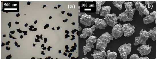
Figure 1.
(a) Compound microscope image and (b) SEM image of the sieved iron powder.
2.2. Laser-Diffraction Particle Sizing
The distribution of particle size of the sieved powder was measured using the Winner2018, a wet laser diffraction analyser (Jinan Winner Particle Instrument Stock Co., Ltd., China) and is presented in Figure 2. The results show that the sieving process was effective in substantially reducing the proportion of particles below 100 µm, despite the stated screen size of 140 µm, which is specified by the manufacturer. Particles smaller than 90 µm accounted for no more than 1.46% of the sample, and the distribution exhibited a monomodal profile with a peak at 165 µm, corresponding to 21.62% by volume. It is important to note that laser diffraction measurements capture the maximum characteristic dimension of each particle. Owing to the pronounced irregularity of the powder morphology, the largest measured particle reached 368 µm, exceeding the <212 µm upper limit specified by the manufacturer. The equivalent spherical diameters of the particles were determined to be D10 = 23.32 µm, D50 = 135.75 µm, and D90 = 214.64 µm.
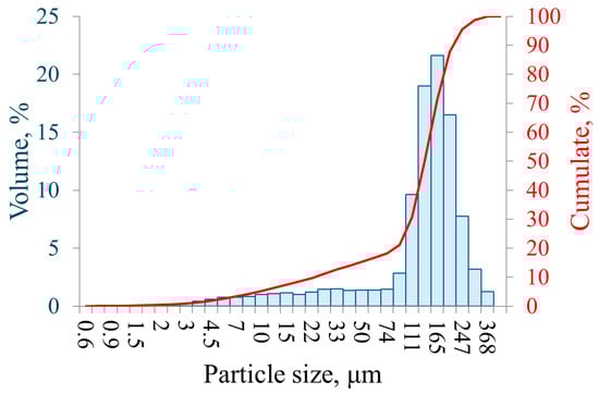
Figure 2.
Particle size distribution of the sieved iron powder.
3. Experimental Method
Figure 3 presents a schematic of the experimental test rig used to investigate hybrid methane–iron powder combustion. The system comprises controlled air and methane supplies regulated by mass flow controllers (Alicat Scientific, Inc, USA), a quartz burner of three concentric tubes, an electric powder feeder, and a quartz drop tube terminating in a metallic chamber for oxide particle collection and exhaust sampling, and a high-speed camera (FASTCAM AX200, Photron, USA). Emissions were characterised using a six-sensor Sauermann Si-CA 230 gas analyser (Sauermann Ltd., UK), an Aerodynamic Particle Sizer (APS™ Model 3321, TSI Incorporated, USA), and a Scanning Mobility Particle Sizer (SMPS™ Model 3938NL56, TSI Incorporated, USA).
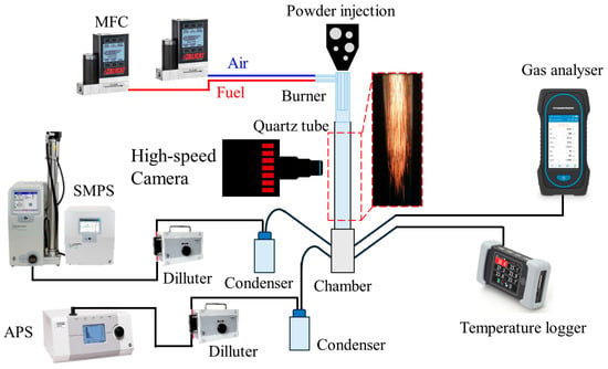
Figure 3.
Schematic of the test rig of the in situ gas and aerosol emissions from the hybrid iron-methane combustion.
A summary of the investigated cases including the methods employed is provided in Table 1.

Table 1.
Summary of the investigated cases.
3.1. Particle Injection
The iron powder was injected with the help of a custom bult electric mini-dispensing device featuring a metal capillary tube, designed to operate without additional carrier gases and to provide accurate adjustment of particle injection. At higher settings, it produces a powder jet at approximately 2 g/min, as captured by the high-speed camera in Figure 4a. Whereas at low settings, it dispenses individual particles at rates of around 8–12 particles per second, as captured by the high-speed camera in Figure 4b. The feed flow rate is controlled by changing the metal capillary tube diameter, electric power, or both. An analytical balance (KERN, ABT 120-5DNM, Germany) was employed to monitor and characterise the consistency of the powder flow over time. It has a sensitivity of 0.0001 g.
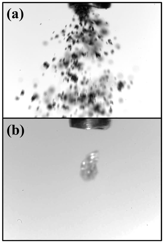
Figure 4.
(a) Flow of iron powder and (b) release of a one iron particle. Particle size and capillary tube are not the same in both images.
3.2. Burner and Combustion Chamber
Dispensed particles were ignited by a nearly flat, non-premixed, lean flame within the quartz burner. The particles are released from the inner tube, the middle tube supplies methane, and the outer tube delivers air at 5 Standard Litre Per Minute (SLPM). The methane–air equivalence ratio is Φ = 0.42. The flat flame features a bright annulus due to the shear layer formed when the methane flow leaves the middle tube, interacting with the air flow, where most of the reactions happen (Figure 5a). The outer diameter of the largest quartz tube, where the flat flame stabilises, is 20 mm. After ignition, particles fall freely through the 250 mm-long quartz drop tube. An individual burning particle appears as a distinct luminous streak (Figure 5b), whereas powder jets formed continuous streak patterns that tended to diverge toward the tube walls (Figure 5c).
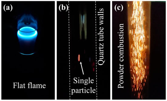
Figure 5.
(a) Flat methane flame inside the burner, (b) combustion of a single particle inside the quartz tube, and (c) combustion of powder inside the quartz tube.
3.3. High-Speed Imaging
High-speed imaging of single-particle combustion was performed to capture the evidence of nanoparticle formation, using the FASTCAM AX200 camera operating at 9k frames per second. The camera is capable of a minimum exposure time of 1 µs. A collimated LED light provided pseudo-backlight illumination (PBI), enabling clear visualisation of particle shadowgraphs during oxidation. The camera was equipped with an extension tube and a variable-zoom macro lens (Venus Optics, Hong Kong, China), offering magnification of up to 7.5× at a 25 mm focal length and f/2.8 aperture to improve spatial resolution. For the present measurements, a magnification of 3.5× was selected, and the field of view (FOV) was positioned downstream of the methane–air flat flame.
3.4. Gas Analysis
The exhaust gas collected from the metal chamber was directed to the probe of a six-sensor Sauermann Si-CA 230 gas analyser measuring O2, CO, NO, NO2, SO2, and H2S, which also computes CO2 concentrations. The electrochemical sensors have the following uncertainties: ±0.2% vol for O2, ±8 ppm for CO, ±5 ppm for NO, ±5 ppm for NO2, ±5 ppm for SO2, and ±5 ppm for H2S according to the manufacturer.
The analyser operates with a maximum pump flow rate of 0.3 L/min. The combined length of the sampling line and analyser hose was sufficient to allow the gas to cool to approximately 37 °C before entering the instrument. Concentrations of CO2, O2, CO, NO, and NO2 were monitored during methane–iron hybrid combustion. Measurements were recorded over a one minute interval after the readings had stabilised and were repeated three times, with an automatic purge performed between each run. The reported values in Section 4 represent the average of the three consecutive measurements.
3.5. In Situ Particle Sizing
The importance of measuring the particle emission from the burning process lies in evaluating the loss of raw material to qualify the recyclability of the powder and assess the emission from the combustion process in terms of fine and Ultrafine Particles (UFPs). Instrumentation to measure the Particle Number Size Distributions (PNSDs) down to a few nanometres in diameter has advanced significantly in the past decades. The most common method for sizing submicron particles involves classification according to electrical mobility, thanks to the high mobility of the electrically charged particles with electrical forces compared to other forces, such as inertia, diffusion, or thermophoretic forces, allowing a precise size selection of the particles [42].
3.5.1. Submicron Sizing
The SMPSTM spectrometers are high resolution sizers that have long been considered the reference systems for sizing submicron particles. The SMPSTM is capable of sizing submicron particles with an accuracy as low as 1% at 100 nm [43]. The spectrometer system is used to condition the aerosols sampled, then sort based on their electrical mobility using an integrated Differential Mobility Analyzer (DMA) system, and count the sorted particles using a Condensation Particle Counter (CPC) [44,45]. The fundamental inverse relationship between the electrical mobility and particle size allows the SMPSTM system to generate an aerosol size distribution. The SMPSTM system used in this study (Figure 3) is composed of a classifier model 3082 equipped with an integrated impactor at the inlet with a cut-off size of ~600 nm to remove larger particles that could lead to sizing errors due to their higher static charge status. The sampled aerosols enter then into a bipolar soft X-ray neutralizer model 3088 integrated in the classifier to control their static charge through a dual neutralisation and charging controlled process that allows reaching an equilibrium of charge [46,47]. The charged particles are then driven to the DMA column, where a high voltage is varied to select one size of particle at a time over the scan range defined for the SMPSTM by the user. For the purpose of this study, two DMA columns were selected with different lower sizing limit capabilities: a Long-DMA (LDMA) model 3081A to scan down to 10 nm and up to 1 µm, and the Nano-DMA (NDMA) model 3085A to size down to 2.5 nm and up to 150 nm. The selected particles exiting the DMA enter the CPC model 3756, with a detection limit D50 = 2.5 nm, to be counted before the next size of particles is selected by the DMA. The sampling pump of the CPC drives the aerosol flow through the whole SMPSTM system, and the system was operated at its highest flow rate capability of 1.5 L/min to minimise the sampling losses due to diffusion, affecting mainly the submicron range of particle sizes of the particles. The CPC can detect up to 3 × 10⁵ particles/cm3 so a dilution system with a dilution factor of 100:1 was added to the setup to avoid saturating the system in case the concentration of the aerosols sampled exceeds the limit of detection of the CPC.
3.5.2. Supermicron Sizing
The particles in the supermicron range of sizes were also measured in this study to complement the information provided by the SMPSTM in the lower range of sizes. Supermicron particles emitted during the combustion of the hybrid flame were quantified using the APSTM 3321 spectrometer (Figure 3). Combustion gas was extracted from the metal chamber and conveyed to the APSTM through a sampling line of enough length to allow the flow to cool down to ambient temperature before entering the instrument, thereby ensuring appropriate operating conditions with regard to the operation requirement of the spectrometer. The APSTM is a high-resolution device, providing single-particle sizing alongside number concentration data over 52 channels of sizes covering a size range from 0.5 µm to 20 µm and designed for real-time characterisation of airborne particles according to their aerodynamic diameter, independent of their optical or geometrical properties as well as composition [48]. This feature is particularly advantageous in the present context, where the physical properties of the particles in the exhaust gases are uncertain. The counting and sizing principle in the APSTM is based on accelerating the sampled aerosol through an inlet orifice, where small particles are accelerated faster than larger ones, and a single signal with two crests is generated each time a particle crosses two partially overlapping laser beams. The time-of-flight (TOF) of the particle between the two laser beams is then measured and converted into an aerodynamic particle diameter. The conversion is performed based on the calibration results obtained using monodisperse NIST traceable polystyrene latex spheres (PSL) with known density (close to unity), refractive index, and sizes. However, for particle densities other than unity, the particles will be incorrectly sized smaller for densities below unity and larger for densities above unity. The magnitude of this difference increases for larger particle sizes. Stokes correction was then introduced for the APSTM to account for that, and can be applied as a post-processing in the software Aerosol Instrument Manager, AIMTM (TSI Incorporated, USA), used to record and process the data from the APSTM if the density of the particles is known [49]. The instrument records also light scattering intensity for particles from 0.37 µm to 20 μm, enabling parallel aerodynamic and optical assessment of combustion-generated particulates.
3.5.3. Experimental Consideration for Particle Sizing
The lean methane–air flame (Φ = 0.4) does not produce soot. Background particle measurements were therefore conducted under methane–air combustion conditions only, without iron powder addition, using the APS™ and SMPS™ spectrometers. No particles were detected by either instrument, resulting in a zero background signal. This confirms that, during hybrid methane–iron powder combustion, all measured particulate emissions originate from iron combustion rather than from the methane–air flame.
Condensation vessels (Figure 3) were incorporated into the experimental setup to collect condensed water vapour during the cooling process of the combustion gases and thereby protect both the APSTM and SMPSTM from potential moisture-related damage. This step was essential to ensure accurate sizing of the particles, as nanoparticle aggregates may form in the exhaust stream, enhanced by the condensation of the vapour on the particles. Although the moisture content of the gas entering both devices was not directly quantified, no condensation was detected in the outlet pipe of the vessel during extended observation. Consequently, any effects of residual moisture or nanoparticle agglomeration on the reported sizing results are judged to be minimal.
3.6. One-Dimensional Simulation Using Cantera
The adiabatic flame temperature and equilibrium species concentrations of methane–air flames were calculated using Cantera, an open-source combustion simulation software. A one-dimensional premixed flame configuration was considered, with the governing equations for one-dimensional flow detailed in [50]. Cantera has been extensively validated in the literature against both two- and three-dimensional computational fluid dynamics (CFDs) simulations and experimental data for hydrocarbon [51] and non-hydrocarbon (e.g., hydrogen [52] and ammonia [53]) flames.
4. Results and Discussion
4.1. In Situ Imaging of the Nanoparticles
The temporal evolution of iron particle oxidation, captured through high-speed imaging, is presented in Figure 6. For reference, an unburned particle falling through the field of view prior to ignition is shown in Figure 6a. Upon crossing the flat flame, particles experience rapid heating followed by melting. In Figure 6b, the particle displays two distinct zones: a dark upper zone and a luminous lower zone with reference to the background. This contrast indicates that heating and melting initiate at the lower surface, where direct interaction with the flat flame occurs. The subsequent melting–oxidation phase is marked by intense light emission arising from exothermic oxidation reactions, as illustrated in Figure 6c. During this stage, the particle transforms from its initially irregular morphology (Figure 1) to a more spherical shape, consistent with internal melting and simultaneous surface oxidation in the liquid state [21]. As combustion progresses and luminosity diminishes, a thick oxide shell develops around the original particle (OP), while the core remains molten and reactive [54]. Continued oxidation within the liquid core generates internal pressure sufficient to rupture the oxide shell, ejecting and dispersing molten NPs into the surrounding region [55]. This results in a bright halo of NPs encircling the now-darkened primary particle, as shown in Figure 6d. These observations confirm that the primary particle is no longer incandescent at this stage, its brightness significantly reduced relative to the surrounding NP cloud, a behaviour consistent with oxide shell formation. The late-stage nanoparticle formation observed here is in agreement with previous findings reported in the literature [56].
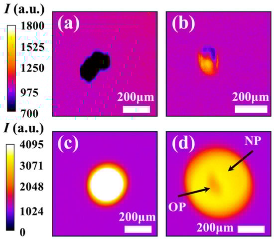
Figure 6.
Combustion phases of a single iron particle captured by the high-speed camera. (a) Unburned particles, (b) particle undergoing heating-melting, (c) particle undergoing liquid oxidation, and (d) particle “OP” releasing nanoparticle “NP” cloud at the decay stage.
4.2. Ex Situ Imaging of the Nanoparticles
Samples of the combusted particles were collected and examined using SEM to provide direct evidence of NP formation, as illustrated in Figure 7. Some particles exhibit cavities that open to the external surface (Figure 7a), a feature particularly common in those with irregular geometries, such as sponge-like particles [57]. The cavity’s edge contains residual NP deposits, consistent with nanoparticle release during the combustion process. Additional confirmation of NP release is provided by a phenomenon frequently reported in the literature: micro-explosions [55] occurring during iron particle combustion (Figure 7b). These events are typically initiated through chemical processes, whereby localised oxidation within internal pores generates internal stresses and gas release. As these stresses build, they can weaken the surrounding oxide shell, producing a mechanical response that may range from mild spallation to more substantial fragmentation. The particle shown in Figure 7b displays a distinctly asymmetric morphology, with one side maintaining a rounded and relatively intact contour, consistent with the action of surface tension, while the opposite side forms an open, pouch-like structure. This damaged region corresponds to the area from which material was expelled during the micro-explosion event.
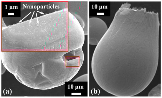
Figure 7.
SEM images of (a) a burned particle with a surface cavity having nanoparticles deposited on the cavity’s edge and (b) an exploded particle.
4.3. Powder Flow Rate
Before undertaking the gas analysis experiments on the hybrid methane–iron flame, it was essential to determine the powder feed rate in order to assess combustion efficiency. The powder injection system was adjusted to achieve flow rates compatible with the operational capacity of the drop tube burner, ensuring that the inner tube did not become blocked at elevated powder loads and that the methane flame remained stable and flat. Initial trials showed that excessive powder feed rates led to flame oscillations or soot formation, both of which represent undesirable operating conditions. The temporal stability of the powder flow was evaluated using an analytical balance (KERN, ABT 120-5DNM, Germany) with a readability of 0.0001 g. Two flow rates were examined, and their cumulative delivered mass over time was recorded, as presented in Figure 8. Measurements were taken every 30 s over a total duration of 240 s. The time-averaged powder feed rates, derived from the change in mass with respect to time, were 0.5 g/min and 1.26 g/min, respectively.
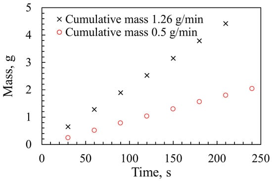
Figure 8.
Powder mass over time at two flow rates.
4.4. Gas Emissions Analysis
Exhaust gas measurements were conducted for three different flames. The first was a methane–air flame (CH4-Air-00), used as a baseline, with a methane–air equivalence ratio of Φ = 0.42. Its adiabatic flame temperature, Tad = 1326 K, was calculated using one-dimensional premixed flame simulations in Cantera. The second and third flames were hybrid methane–iron–air flames, operated at the same methane–air equivalence ratio and denoted CH4-Fe-05 and CH4-Fe-12, corresponding to iron mass flow rates of 0.5 g/min and 1.26 g/min, respectively. The measured results are presented in Figure 9. The methane baseline flame (CH4-Air-00) exhibited a residual oxygen concentration of YO2 = 11.52 vol%, confirming its lean character. Cantera calculations yielded a comparable value of YO2 = 11.55 vol%, in agreement with the measurements. Upon introducing iron powder, the residual oxygen content decreased, demonstrating Fe oxidation, which consumes oxygen. The remaining oxygen levels were YO2 = 11.12 vol% for CH4-Fe-05 and 10.90 vol% for CH4-Fe-12. However, the reductions relative to the baseline appear modest compared with the oxygen demand required for complete Fe combustion, indicating partial oxidation. Theoretical estimates show that only 15.15 vol% and 23.43 vol% of the oxygen required for full Fe oxidation were consumed in the CH4-Fe-05 and CH4-Fe-12 flames, respectively. The complete calculation method and the reasons underlying this partial oxidation are examined in Section 4.5. Furthermore, the results show an increase in CO and CO2 emissions with increasing Fe feed rate. Notably, hybrid methane–iron co-firing was found to contribute to additional carbon emissions, suggesting that Fe introduces reaction pathways promoting carbon dioxide formation. The measured CO2 from the baseline flame (CH4-Air-00) was 5.28 vol%, whereas Cantera simulations predicted 4.27 vol%. This discrepancy arises from the assumptions inherent in the simulations, which consider a one-dimensional, premixed flame, whereas the experimental flame is three-dimensional and non-premixed. At 0.5 g/min (CH4-Fe-05), the CO2 concentration reached 5.5 vol%, representing a 0.22 vol% increase relative to the methane–air flame. At 1.26 g/min (CH4-Fe-12), the CO2 emission was increased by 0.35 vol% compared with the baseline. Although these increments may appear modest, they are significant given the small scale of the hybrid burner. Relevant oxidation mechanisms for methane–air, Fe-air, and Fe-C reactions have been retrieved from the literature and analysed in Section 4.6 to elucidate how Fe contributes to enhanced carbon emissions. Regarding NOx emissions, a slight reduction was observed when Fe powder was introduced, amounting to only a few ppm at each feed rate, which is considered negligible.
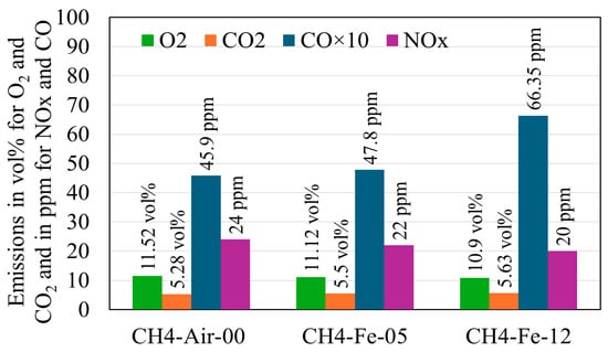
Figure 9.
Gas emissions from both the methane–air flame and hybrid iron–methane flames.
4.5. Analysis of Oxygen Consumption
A theoretical calculation of the oxygen required to fully oxidise Fe is necessary to quantify the fraction of unburned iron. The following steps outline this analysis, using the hybrid flame CH4-Fe-05 with an Fe mass flow rate of 0.5 g/min as an example. The corresponding molar flow rate () of Fe is derived from the mass flow rate () and the molar mass ().
The collected oxidised powder exhibits a visible black colour, indicating that it is predominantly magnetite (). The relevant oxidation reaction producing magnetite indicates that each mole of Fe requires 2/3 mole of O2, representing the stoichiometric requirement.
Accordingly, the molar flow rate of oxygen required for complete oxidation can be calculated.
The air flow rate entering the burner at standard conditions (temperature and pressure ) is first determined, and, assuming room pressure equals standard pressure, the actual air flow rate at ambient temperature is obtained.
From this, the molar flow rate of air () can be defined, allowing the molar flow rate of oxygen at the burner inlet to be calculated.
where is the gas constant.
At the burner outlet, in the absence of Fe injection (i.e., methane–air flame only with YO2 = 11.53 vol% from Figure 7), the molar flow rate of oxygen can be determined.
From these values, the theoretical excess oxygen at the burner outlet, assuming complete Fe oxidation to , can be estimated and converted to a corresponding volume percentage.
The measured residual oxygen of YO2 = 11.12 vol% from CH4-Fe-05 is substantially higher than the predicted excess of 8.84 vol% for fully oxidised Fe, indicating that only a small fraction of the iron actually oxidised. The consumed oxygen relative to the baseline methane–air flame can then be calculated, from which the fraction of oxidised Fe is determined.
Using the above method and by considering the hybrid flame CH4-Fe-12 with an Fe mass flow rate of 1.26 g/min, the fraction of oxidised Fe is 23.43 vol%.
The calculated oxidation fractions of 15.25% and 23.43% for the CH4-Fe-05 and CH4-Fe-12 flames, respectively, at oxygen lean conditions, indicate that iron combustion is strongly constrained by the limited availability of oxygen at the particle surface. The local oxygen partial pressure along the particle trajectory is reduced by the burner’s coaxial injection configuration, in which iron particles enter through the inner tube, methane through the surrounding annulus, and air through the outer tube. Consequently, particles first encounter a methane-rich, oxygen-depleted environment that delays the onset of oxidation (e.g., ignition). Furthermore, iron oxidation competes directly with methane oxidation: short-lived intermediates (e.g., CO and H2) and radicals (e.g., H, CH, and CH3) rapidly consume oxygen, reducing the flux of O2 available to reach the particle’s surface. Oxygen transport is therefore hindered not only by the scarcity of oxidiser but also by diffusion resistance in a chemically active gas mixture containing multiple reactive species. This environment reduces Fe oxidation rates, increases susceptibility to rapid extinction [58], and, in the case of larger particles, can lead to failed ignition due to the formation of an early oxide layer that inhibits further inward oxidation [59]. Collectively, these effects generate a pronounced oxygen-deficient microenvironment and, as a result, poor iron combustion efficiency. Two potential strategies may be proposed to mitigate the limited oxidation observed under oxygen-lean conditions. First, modification of the burner design could be implemented such that iron particles are exposed to the oxidiser prior to encountering the methane-rich stream. Ensuring early contact with oxygen would increase the local oxygen partial pressure at the particle surface, thereby promoting earlier ignition and enhanced oxidation. Second, the adoption of oxy-combustion conditions, achieved by increasing the oxygen concentration in the oxidising stream, represents a viable alternative. Previous studies [16,18,37] have shown that elevated oxygen levels lead to increased iron particle burn times, which is indicative of improved oxidation rates. However, increasing the oxygen concentration is also expected to influence nanoparticle formation, leading to higher nanoparticle concentrations and affecting the nanoparticle sizes and agglomeration morphology [37].
Figure 10 presents SEM images of sample particles, some of which display spherical morphologies indicative of liquid phase oxidation, while others remain unburned, suggesting failed combustion. Cross-sectional analysis of a representative spherical particle, performed by Energy Dispersive X-ray Spectrometry (EDXS, Oxford Instruments PLC, UK), reveals a characteristic partial oxidation structure in Figure 11. The particle is composed of two distinct solidified phases: an iron-rich core (Figure 11a) and an outer oxide shell (Figure 11b). This core–shell configuration is consistent with partial oxidation during melting. The particle experienced auto-quenching, wherein the exterior (oxide phase) solidified first, an effect analogous to behaviour reported during manual quenching experiments in the literature [54,60].
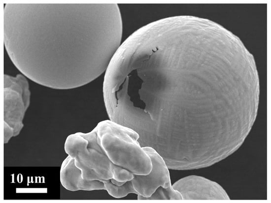
Figure 10.
SEM image showing burned spherical particles and unburned irregular particles.
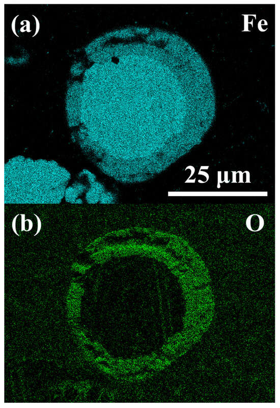
Figure 11.
EDXS images of a partially oxidised particle showing (a) a rich elemental Fe core and (b) a rich elemental O shell.
4.6. Analysis of Carbon Dioxide Formation
Understanding the reasons that lead to CO2 increase in the hybrid methane–iron flame compared with the baseline methane–air flame requires investigating the chemical reactions responsible for this. It is worth noting that the iron powder used in this study does not contain carbon impurities after analysing it using EDXS; therefore, the measured CO2 primarily originates from methane combustion.
Several reaction mechanisms are analysed, including the GRI 3.0 mechanism for natural gas and methane combustion [61], methane–iron–pentacarbonyl mechanisms [62,63], and iron–air simplified mechanism [64]. This study is not intended to delve into detailed reaction kinetics, as its primary focus is emission analysis; however, we attempt to clarify the observed and initially unexpected increase in CO2 in the hybrid methane–iron flame in Figure 9. Table 2 summarises key reactions that are both indirect and direct routes to CO2. In the methane–air baseline, CO2 is formed predominantly through the radical-driven CO oxidation routes R1–R4. When iron is introduced, an additional and entirely new CO2 source emerges through oxidation of iron-carbon intermediates, most notably via R5 (FeCO + O → Fe + CO2). Simultaneously, iron oxidation chemistry enhances the overall oxidising environment: reactions R6 and R7 generate O atoms, while R8 and R9 regenerate OH radicals, both of which accelerate the canonical CO → CO2 conversion pathways (R1–R4). The exothermicity of the Fe/FeO/FeO2 [64] cycle further increases local temperature, strengthening these effects by raising reaction rates. To illustrate this interplay between the species and reactions of Table 2, a reaction network diagram was developed and schematised in Figure 12. Another possible CO2-forming route, the reduction of Fe2O3 by CO (Fe2O3 + 3 CO → 2 Fe + 3 CO2) [63], may also contribute; however, it is not included in Table 2 and reaction network (Figure 10) because Fe2O3 formation involves multiple intermediate oxidation steps that are not directly connected to the species considered in Table 2. Taken together, the direct CO2 production from Fe-C species and the radical-enhanced CO oxidation promoted by iron oxidation chemistry offer a coherent explanation for the increased CO2 level observed in the hybrid flames relative to methane–air combustion, as indicated in Figure 9.
Table 2.
Literature-derived reactions potentially contributing to Co2 generation in a hybrid methane–iron–air flame.
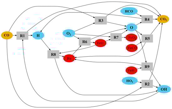
Figure 12.
Reaction network diagram of some reactions in the hybrid methane–iron combustion leading to CO2 formation.
4.7. Supermicron Particles Emission
Figure 13 shows the time-averaged PNSDs measured by the APSTM for the CH4-Fe-12 flame, expressed as the normalised concentration within each size bin. The sampling interval was set to 20 s, and a total number of 55 scans were recorded for a total scan time of ~18 min, taking into account the limited powder-feeding capacity. The monomodal distribution shows particles with aerodynamic diameters ranging from 0.523 μm to approximately 6 μm. The main mode is detected around 2 µm. Supermicron particles are likely generated by disruptive combustion events, such as micro-explosions, similar to those illustrated in Figure 7b. We analysed images from Peng et al. [55] micro-explosions of single iron particles containing carbon impurities, and it was found that fragments in the range of 8–34 μm were produced, and the primary particle remains intact following the event. Aerodynamic particle measurements obtained from a vertical entrained-flow reactor by Wiinikka et al. [41] reported particle sizes up to 20 μm in Fe-air flames, albeit at low concentrations for a comparable feed rate of 2.5 g/min, attributing these larger particles to agglomerates of smaller ones. It is notable that, in the present study, according to the results of the PNSDs shown in Figure 13, more than 99% of the particles detected were below 6 µm. The inclusion of a condensation vessel effectively minimised water vapour-induced agglomeration, resulting in only particles below ~6 μm being present in the exhaust. The distribution seems cropped at the sub-micron range, below 0.523 nm, toward the lower range of sizes not captured by the APSTM. This points towards the presence of particles in the submicron range, which would be interesting to investigate. The possible presence of submicron particles was also reported by Wiinikka et al. [41], who observed a peak of concentration around 0.492 μm. The emission of fine and ultrafine particles is examined in the following section.
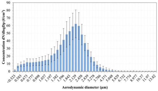
Figure 13.
Particle number size distribution from the exhaust gases as measured by the APSTM.
4.8. Submicron Particles Emission
Submicron particle emission from the burning process is investigated in order to identify the minimum size of particles emitted from the burning process as well as the total concentration of particles emitted in the submicron range. A single SMPSTM scan is recorded over a duration of 1 min and repeated five times, then the PSDs obtained were averaged over time. The time averaged PNSD relative to the emission from the burning process of the powder tested in this study and measured with the SMPSTM system is shown in Figure 14.
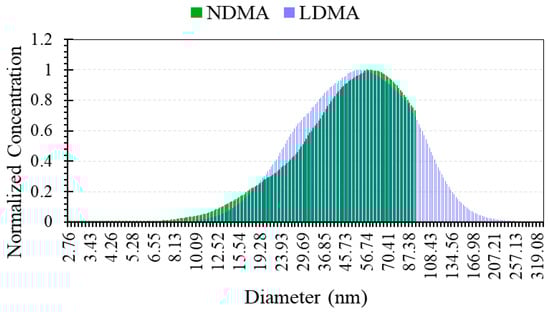
Figure 14.
Submicron PNSDs from the exhaust gases as measured with the SMPSTM.
The PNSD measurements were repeated using both DMA columns to assess mainly the level of particle emissions sub-10 nm from the hybrid flame. The NDMA has a detection limit lower than that of the LDMA column with reduced diffusion losses through the column due to its optimised design. The results obtained using both DMA columns showed comparable polydisperse PNSDs with Geometric Standard Deviations GSD value of ~6. The mode of the PNSDs is found around 56 nm with a shift of ~11% between the modes detected, respectively, with the NDMA and the LDMA. It is clearly identified that the burning process emission was mostly in the Ultrafine Particles (UFPs) size range, with 89% of the particles emitted below 100 nm. The emission in the sub-10 nm range of sizes was found not relevant, less than 1%, for the size of raw iron powder considered in this study. It is also important to notice that the total concentration of the particles measured with the SMPSTM reached ~4 × 10⁷ particles/cm3 which is a substantial amount. In fact, knowing the density of the iron powder (i.e., 7.87 g/cm3) and assuming all the particles are spherical with a mean diameter of 56 nm, this would correspond to a mass concentration of submicron particles of ~30 µg/m3. Table 3 summarises the key findings from the submicron particle emission experiment.
Table 3.
Summary of submicron PNSD measurement from the hybrid methane–iron–air flame.
5. Conclusions
This study provides an experimental diagnostic and characterisation of hybrid methane–iron powder combustion, combining microscopic and high-speed imaging, ex situ particle sizing, in situ emissions analysis, and aerosol measurements. The aim was to evaluate the use of iron powder as a carbon-free and sustainable fuel. The used iron powder has an irregular morphology, and it was sieved to generate an average particle size of D50 = 135.75 µm. The following conclusions presented are restricted to the conditions, cases, and powder type examined in this study.
High-speed imaging confirmed that particles undergo rapid heating, melting, oxide shell growth, and late-stage nanoparticle release. SEM micrographs provided direct evidence of cavity formation, micro-explosion, and nanoparticle release.
Gas phase analysis demonstrated that introducing iron at 0.5 g/min and 1.26 g/min reduced residual O2 only modestly, corresponding to iron oxidation fractions of 15.15% and 23.43%, respectively, indicating oxygen-limited combustion. Hybrid combustion increased CO2 emissions by 0.22 vol% (at 0.5 g/min) and 0.35 vol% (at 1.26 g/min) relative to the methane–air flame baseline, attributable to both direct Fe–C oxidation pathways and enhanced radical-driven CO conversion, as supported by reactions drawn from literature. NOx reductions were negligible.
Aerosol measurements revealed a supermicron mode centred at ~2 µm, with detectable particles up to ~6 µm, consistent with disruptive oxidation events. Submicron emissions were dominated by UFPs: 89% of the population was below 100 nm, with a modal diameter of ~56 nm and a total number concentration of ~4 × 107 cm−3, corresponding to an estimated mass concentration of ~30 µg/m3. The negligible contribution of sub-10 nm species (<1%) further reflects the influence of the relatively large raw powder size.
The significant UFP emission observed should be investigated further to better qualify the metallic powder combustion process. Although the mass loss associated with UFPs might still be considered small, their high number concentration and nanoscale size still warrant attention from both health and material-loss perspectives. However, it would be important, on the one hand, to characterise these emissions with regard to the characteristics of the raw metallic powder and to the conditions of the combustion process, to assess the impact of particle emission on closing the fuel cycle of metallic powders.
These findings show that while iron participates only partially in oxidation under local fuel-rich, oxygen-limited conditions, its presence substantially modifies both gas phase chemistry and particle phase emissions. Cofiring iron and methane increases CO2 emissions, though burner optimisation or premixed strategies could help mitigate this. Future work may focus on enhancing iron oxidation by addressing the oxygen-limited conditions identified in this study, for example, through burner design optimisation, modified injection strategies, or premixed and oxygen-enriched configurations.
Author Contributions
Z.M.; Conceptualization, methodology, software, validation, formal analysis, investigation, resources, data curation, writing—original draft preparation, writing—review and editing, visualisation, project administration, funding acquisition and A.K.; methodology, software, validation, formal analysis, investigation, resources, data curation, writing—original draft preparation, writing—review and editing, visualisation. All authors have read and agreed to the published version of the manuscript.
Funding
This work was funded by The Royal Society, Research Grants RGS\R2\242432.
Institutional Review Board Statement
Not applicable.
Informed Consent Statement
Not applicable.
Data Availability Statement
Data is contained within the article.
Acknowledgments
The authors are very grateful to the funder and to NTU for its support through the SST Imaging Suite. The authors would also like to thank TSI Incorporated for the instrument resources and valuable support.
Conflicts of Interest
Author Amine Koched was employed by the company TSI France Inc. The remaining author declares that the research was conducted in the absence of any commercial or financial relationships that could be construed as a potential conflict of interest.
Abbreviations
The following abbreviations are used in this manuscript:
| APSTM | Aerodynamic Particle Sizer |
| CPC | Condensation Particle Counter |
| DMA | Differential Mobility Analyzer |
| EDXS | Energy Dispersive X-ray Spectrometry |
| FOV | Field Of View |
| LDMA | Long Differential Mobility Analyzer |
| NDMA | Nano Differential Mobility Analyzer |
| NP | Nanoparticles |
| OP | Original Particle |
| PBI | Pseudo Backlight Illumination |
| PNSDs | Particle Number Size Distribution |
| PSL | Polystyrene latex spheres |
| TOF | Time-Of-Flight |
| SEM | Scanning Electron Microscope |
| SMPSTM | Scanning Mobility Particle Sizer |
| SLPM | Standard litre per minute |
| UFPs | Ultra Fine Particles |
References
- International Energy Agency. Global Energy Review 2025. March 2025. Available online: https://www.iea.org/reports/global-energy-review-2025 (accessed on 7 August 2025).
- International Energy Agency. Renewables 2024: Analysis and Forecast to 2030. October 2024. Available online: https://www.iea.org/reports/renewables-2024 (accessed on 7 August 2025).
- Stavytskyy, A.; Dligach, A. The Global Economic Model in Crisis: An Analysis of the Obstacles to the Sustainable Development Goals. Sustainability 2025, 17, 8537. [Google Scholar] [CrossRef]
- Guerdalli, S.; Trabelsi, E. COVID-19 and the Merit-Order Effect of Wind Energy: The Case of Nord Pool Electricity Markets. Sustainability 2025, 17, 9859. [Google Scholar] [CrossRef]
- Long, T.; Shao, L.; Zhang, T.; Chen, Z.; Zhang, Y.; Xing, J.; Zhang, Y. Energy Price Fluctuation and Urban Surveyed Unemployment in Transition Context: MF-VAR Evidence. Sustainability 2025, 17, 10017. [Google Scholar] [CrossRef]
- Hadi, A.I.; Yan, A.; Hu, Y.; Lin, B.; Zhou, T.; Ouyang, D.; Tang, J. A comprehensive review of carbon capture: From conventional to emerging electrochemical technologies. Energy 2025, 9, 100415. [Google Scholar] [CrossRef]
- Thiedemann, T.M.; Wark, M. A Compact Review of Current Technologies for Carbon Capture as Well as Storing and Utilizing the Captured CO2. Processes 2025, 13, 283. [Google Scholar] [CrossRef]
- Thackeray, M.M.; Wolverton, C.; Isaacs, E.D. Electrical energy storage for transportation—Approaching the limits of, and going beyond, lithium-ion batteries. Energy Environ. Sci. 2012, 5, 7854–7863. [Google Scholar] [CrossRef]
- Gwayi, I.; Ayeng’o, S.P.; Kimambo, C.Z.M. Selection of electrochemical and electrical energy storage systems for off-grid renewable energy mini-grids: A review. Clean. Eng. Technol. 2025, 25, 100906. [Google Scholar] [CrossRef]
- Yue, M.; Lambert, H.; Pahon, E.; Roche, R.; Jemei, S.; Hissel, D. Hydrogen energy systems: A critical review of technologies, applications, trends and challenges. Renew. Sustain. Energy Rev. 2021, 146, 111180. [Google Scholar] [CrossRef]
- Salmon, N.; Bañares-Alcántara, R. Green ammonia as a spatial energy vector: A review. Sustain. Energy Fuels 2021, 5, 2814–2839. [Google Scholar] [CrossRef]
- Bergthorson, J.M. Recyclable metal fuels for clean and compact zero-carbon power. Prog. Energy Combust. Sci. 2018, 68, 169–196. [Google Scholar] [CrossRef]
- Bergthorson, J.M.; Goroshin, S.; Soo, M.J.; Julien, P.; Palecka, J.; Frost, D.L.; Jarvis, D.J. Direct combustion of recyclable metal fuels for zero-carbon heat and power. Appl. Energy 2015, 160, 368–382. [Google Scholar] [CrossRef]
- Julien, P.; Bergthorson, J.M. Enabling the metal fuel economy: Green recycling of metal fuels. Sustain. Energy Fuels 2017, 1, 615–625. [Google Scholar] [CrossRef]
- Boretti, A. The perspective of hydrogen direct reduction of iron. J. Clean. Prod. 2023, 429, 139585. [Google Scholar] [CrossRef]
- Ning, D.; Shoshin, Y.; van Oijen, J.A.; Finotello, G.; de Goey, L.P.H. Burn time and combustion regime of laser-ignited single iron particle. Combust. Flame 2021, 230, 111424. [Google Scholar] [CrossRef]
- Ning, D.; Shoshin, Y.; van Oijen, J.; Finotello, G.; de Goey, P. Size evolution during laser-ignited single iron particle combustion. Proc. Combust. Inst. 2023, 39, 3561–3571. [Google Scholar] [CrossRef]
- Ning, D.; Hazenberg, T.; Shoshin, Y.; van Oijen, J.A.; Finotello, G.; de Goey, L.P.H. Experimental and theoretical study of single iron particle combustion under low-oxygen dilution conditions. Fuel 2024, 357, 129718. [Google Scholar] [CrossRef]
- Li, S.; Huang, J.; Weng, W.; Qian, Y.; Lu, X.; Aldén, M.; Li, Z. Ignition and combustion behavior of single micron-sized iron particle in hot gas flow. Combust. Flame 2022, 241, 112099. [Google Scholar] [CrossRef]
- Panahi, A.; Chang, D.; Schiemann, M.; Fujinawa, A.; Mi, X.; Bergthorson, J.M.; Levendis, Y.A. Combustion behavior of single iron particles-part I: An experimental study in a drop-tube furnace under high heating rates and high temperatures. Appl. Energy Combust. Sci. 2023, 13, 100097. [Google Scholar] [CrossRef]
- Mansouri, Z. New insights into iron fuel combustion: Integrated in-situ and ex-situ diagnostics of ignition delay, melting–oxidation, disruptive phenomena and nanoparticle sizing. Meas. Energy 2025, 8, 100073. [Google Scholar] [CrossRef]
- Sun, J.-H.; Dobashi, R.; Hirano, T. Structure of flames propagating through metal particle clouds and behavior of particles. Symp. Int. Combust. 1998, 27, 2405–2411. [Google Scholar] [CrossRef]
- Sun, J.-H.; Dobashi, R.; Hirano, T. Combustion Behavior of Iron Particles Suspended in Air. Combust. Sci. Technol. 2000, 150, 99–114. [Google Scholar] [CrossRef]
- Tang, F.-D.; Goroshin, S.; Higgins, A.; Lee, J. Flame propagation and quenching in iron dust clouds. Proc. Combust. Inst. 2009, 32, 1905–1912. [Google Scholar] [CrossRef]
- Krenn, T.; Li, T.; Hebel, J.; Böhm, B.; Dreizler, A. Evaluation of a novel measurement method for the laminar burning speed in laminar lifted iron dust flames. Fuel 2024, 366, 131266. [Google Scholar] [CrossRef]
- Prasidha, W.; Baigmohammadi, M.; Shoshin, Y.; de Goey, P. Towards an efficient metal energy carrier for zero–emission heating and power: Iron powder combustion. Combust. Flame 2024, 268, 113655. [Google Scholar] [CrossRef]
- Baigmohammadi, M.; Prasidha, W.; Stevens, N.C.; Shoshyn, Y.L.; Spee, T.; de Goey, P. Towards utilization of iron powders for heating and power. Appl. Energy Combust. Sci. 2023, 13, 100116. [Google Scholar] [CrossRef]
- Sohrabi, M.; Ghobadian, B.; Najafi, G.; Prasidha, W.; Baigmohammadi, M.; de Goey, P. Experimental and Statistical Analysis of Iron Powder for Green Heat Production. Sustainability 2024, 16, 9416. [Google Scholar] [CrossRef]
- Sohrabi, M.; Ghobadian, B.; Najafi, G.; Choisez, L.; Prasidha, W.; Baigmohammadi, M.; de Goey, P. Iron powder particles as a clean and sustainable carrier: Investigating their impact on thermal output. Process Saf. Environ. Prot. 2024, 188, 957–969. [Google Scholar] [CrossRef]
- Julien, P.; Whiteley, S.; Goroshin, S.; Soo, M.J.; Frost, D.L.; Bergthorson, J.M. Flame structure and particle-combustion regimes in premixed methane–iron–air suspensions. Proc. Combust. Inst. 2015, 35, 2431–2438. [Google Scholar] [CrossRef]
- McRae, M.; Julien, P.; Salvo, S.; Goroshin, S.; Frost, D.L.; Bergthorson, J.M. Stabilized, flat iron flames on a hot counterflow burner. Proc. Combust. Inst. 2019, 37, 3185–3191. [Google Scholar] [CrossRef]
- Hulsbos, M.R.; Hermanns, R.T.E.; Bastiaans, R.J.M.; de Goey, L.P.H. The Heat Flux Method for hybrid iron–methane–air flames. Combust. Flame 2024, 266, 113531. [Google Scholar] [CrossRef]
- Hulsbos, M.R.; Hermanns, R.T.E.; Bastiaans, R.J.M.; de Goey, L.P.H. The laminar burning velocity of hybrid iron-methane-air flames. Combust. Flame 2025, 279, 114274. [Google Scholar] [CrossRef]
- Choisez, L.; van Rooij, N.E.; Hessels, C.J.; da Silva, A.K.; Filho, I.R.S.; Ma, Y.; de Goey, P.; Springer, H.; Raabe, D. Phase transformations and microstructure evolution during combustion of iron powder. Acta Mater. 2022, 239, 118261. [Google Scholar] [CrossRef]
- Liu, X.; Wang, D.; Fang, S.; Zhang, S.; Yang, L.; Li, J. Mitigating thermoacoustic instabilities in a Rijke tube burner using iron nanopowder additives. Exp. Therm. Fluid Sci. 2025, 166, 111472. [Google Scholar] [CrossRef]
- Ning, D.; Shoshin, Y.; van Oijen, J.A.; Finotello, G.; de Goey, L.P.H. Critical temperature for nanoparticle cloud formation during combustion of single micron-sized iron particle. Combust. Flame 2022, 244, 112296. [Google Scholar] [CrossRef]
- Chang, D.; Thijs, L.C.; Panahi, A.; Mi, X.; Bergthorson, J.M.; Levendis, Y.A. Effects of oxygen concentration on nanoparticle formation during combustion of iron powders. Fuel 2025, 397, 135366. [Google Scholar] [CrossRef]
- Prasidha, W.; Baigmohammadi, M.; Shoshin, Y.; de Goey, P. Optimizing iron powder combustion: Influence of particle size on flame stability, nanoparticle formation, and nitric oxide emission. Combust. Flame 2025, 275, 114068. [Google Scholar] [CrossRef]
- Tóth, P.; Ögren, Y.; Sepman, A.; Gren, P.; Wiinikka, H. Combustion behavior of pulverized sponge iron as a recyclable electrofuel. Powder Technol. 2020, 373, 210–219. [Google Scholar] [CrossRef]
- Buchheiser, S.; Deutschmann, M.P.; Rhein, F.; Allmang, A.; Fedoryk, M.; Stelzner, B.; Harth, S.; Trimis, D.; Nirschl, H. Particle and Phase Analysis of Combusted Iron Particles for Energy Storage and Release. Materials 2023, 16, 2009. [Google Scholar] [CrossRef]
- Wiinikka, H.; Vikström, T.; Wennebro, J.; Toth, P.; Sepman, A. Pulverized Sponge Iron, a Zero-Carbon and Clean Substitute for Fossil Coal in Energy Applications. Energy Fuels 2018, 32, 9982–9989. [Google Scholar] [CrossRef]
- Flagan, R.C. Electrical Mobility Methods for Submicrometer Particle Characterization. In Aerosol Measurement: Principles, Techniques, and Applications, 3rd ed.; John Wiley & Sons, Ltd.: Hoboken, NJ, USA, 2011; pp. 339–364. [Google Scholar] [CrossRef]
- TSI Incorporated. Electrostatic Classifier Model 3082, SMPSTM Model 3938, Operation and Service Manual, USA; TSI Incorporated: Shoreview, MN, USA, 2024. [Google Scholar]
- TSI Incorporated. Fundamentals of Condensation Particle Counters (CPC) and Scanning Mobility Particle Sizer (SMPSTM) Spectrometers, USA; Application Note CPC-003-US; TSI Incorporated: Shoreview, MN, USA, 2014. [Google Scholar]
- Welker, R.W. Size Analysis and Identification of Particles. In Developments in Surface Contamination and Cleaning; William Andrew Publishing: Norwich, NY, USA, 2012; pp. 179–213. [Google Scholar] [CrossRef]
- Fuchs, N.A. On the stationary charge distribution on aerosol particles in a bipolar ionic atmosphere. Geofis. Pura E Appl. 1963, 56, 185–193. [Google Scholar] [CrossRef]
- Wiedensohler, A. An approximation of the bipolar charge distribution for particles in the submicron size range. J. Aerosol Sci. 1988, 19, 387–389. [Google Scholar] [CrossRef]
- Peters, T.M.; Ott, D.; O’shaughnessy, P.T. Comparison of the Grimm 1.108 and 1.109 Portable Aerosol Spectrometer to the TSI 3321 Aerodynamic Particle Sizer for Dry Particles. Ann. Occup. Hyg. 2006, 50, 843–850. [Google Scholar] [CrossRef] [PubMed]
- Wang, H.-C.; John, W. Particle Density Correction for the Aerodynamic Particle Sizer. Aerosol Sci. Technol. 1987, 6, 191–198. [Google Scholar] [CrossRef]
- Goodwin, D.G.; Speth, R.L.; Moffat, H.K.; Weber, B.W. Cantera: An Object-Oriented Software Toolkit for Chemical Kinetics, Thermodynamics, and Transport Processes, Version 3.0; Zenodo: Geneva, Switzerland, 2021. [Google Scholar] [CrossRef]
- Chen, B.-S.; Garner, A.L.; Bane, S.P.M. Simulation of flame speed enhancement of a hydrocarbon flame with a microwave field. Combust. Flame 2019, 207, 250–264. [Google Scholar] [CrossRef]
- Maxwell, B.; Mével, R.; Melguizo-Gavilanes, J. Spherically expanding flame simulations using Cantera coupled to an unsteady Lagrangian formulation. Int. J. Hydrogen Energy 2024, 51, 948–960. [Google Scholar] [CrossRef]
- Guo, J.; Liu, P.; Serrano-Bayona, R.; Es-Sebbar, E.-T.; Gao, X.; Roberts, W.L.; Im, H.G. Stability and NO formation of ammonia/methane non-premixed flames under O2/CO2 environments. Combust. Flame 2026, 283, 114621. [Google Scholar] [CrossRef]
- Deutschmann, M.P.; Sperling, A.; Covini, E.; Böhm, B.; Dreizler, A.; Nirschl, H. Single iron particle combustion—A morphology study of partially oxidized iron particles. Powder Technol. 2024, 445, 120102. [Google Scholar] [CrossRef]
- Peng, F.; Liu, H.; Kong, C.; Mi, X.; Tian, B.; Zheng, Y.; Xu, S.; Cai, W. Micro-explosion of burning iron particles with carbon impurity. Combust. Flame 2025, 274, 113974. [Google Scholar] [CrossRef]
- Li, T.; Nguyen, B.-D.; Gao, Y.; Elsässer, L.; Ning, D.; Scholtissek, A.; van Duin, A.C.; Hasse, C.; Böhm, B. Critical nanoparticle formation in iron combustion: Single particle experiments with in-situ multi-parameter diagnostics aided by multi-scale simulations. Fuel 2026, 404, 136303. [Google Scholar] [CrossRef]
- Huang, J.; Li, S.; Sanned, D.; Xu, L.; Xu, S.; Wang, Q.; Stiti, M.; Qian, Y.; Cai, W.; Berrocal, E.; et al. A detailed study on the micro-explosion of burning iron particles in hot oxidizing environments. Combust. Flame 2022, 238, 111755. [Google Scholar] [CrossRef]
- Mi, X. Theoretical elucidation of the hindering effect of oxide-layer growth on the ignition of iron particles. Combust. Flame 2025, 279, 114310. [Google Scholar] [CrossRef]
- Fujinawa, A.; Thijs, L.C.; Jean-Philyppe, J.; Panahi, A.; Chang, D.; Schiemann, M.; Levendis, Y.A.; Bergthorson, J.M.; Mi, X. Combustion behavior of single iron particles, Part II: A theoretical analysis based on a zero-dimensional model. Appl. Energy Combust. Sci. 2023, 14, 100145. [Google Scholar] [CrossRef]
- Sperling, A.; Deutschmann, M.P.; Ning, D.; Spielmann, J.; Li, T.; Kramm, U.I.; Nirschl, H.; Böhm, B.; Dreizler, A. Oxidation progress and inner structure during single micron-sized iron particles combustion in a hot oxidizing atmosphere. Fuel 2025, 381, 133147. [Google Scholar] [CrossRef]
- Smith, G.P.; Golden, D.M.; Frenklach, M.; Moriarty, N.W.; Eiteneer, B.; Goldenberg, M.; Bowman, C.T.; Hanson, R.K.; Song, S.; Gardiner, W.C., Jr.; et al. GRI-Mech 3.0. Available online: http://www.me.berkeley.edu/gri_mech/ (accessed on 1 November 2025).
- Rumminger, M.D.; Reinelt, D.; Babushok, V.; Linteris, G.T. Numerical study of the inhibition of premixed and diffusion flames by iron pentacarbonyl. Combust. Flame 1999, 116, 207–219. [Google Scholar] [CrossRef]
- Nanjaiah, M.; Pilipodi-Best, A.; Lalanne, M.R.; Fjodorow, P.; Schulz, C.; Cheskis, S.; Kempf, A.; Wlokas, I.; Rahinov, I. Experimental and numerical investigation of iron-doped flames: FeO formation and impact on flame temperature. Proc. Combust. Inst. 2021, 38, 1249–1257. [Google Scholar] [CrossRef]
- Thijs, L.C.; van Gool, C.E.A.G.; Ramaekers, W.J.S.; van Oijen, J.A.; de Goey, L.P.H. Resolved simulations of single iron particle combustion and the release of nano-particles. Proc. Combust. Inst. 2023, 39, 3551–3559. [Google Scholar] [CrossRef]


Disclaimer/Publisher’s Note: The statements, opinions and data contained in all publications are solely those of the individual author(s) and contributor(s) and not of MDPI and/or the editor(s). MDPI and/or the editor(s) disclaim responsibility for any injury to people or property resulting from any ideas, methods, instructions or products referred to in the content. |
© 2026 by the authors. Licensee MDPI, Basel, Switzerland. This article is an open access article distributed under the terms and conditions of the Creative Commons Attribution (CC BY) license.