Abstract
Optimization design is an effective strategy for reducing carbon emissions in building structures. Various exhaustive and metaheuristic methods have been proposed to optimize the carbon emissions of structural components, which has primarily focused on sustainable design during the construction phase. This study proposes a hybrid approach for the life cycle sustainable design of reinforced concrete components, encompassing the material production, construction, carbonization, and end-of-life phases. The resistance of structural components was evaluated through time-dependent reliability indices, and surrogate models were developed using machine learning techniques. The surrogate models were subsequently integrated into a dual-objective genetic algorithm for life cycle sustainable design. Based on the proposed approach, numerical examples including a singly reinforced beam and a biaxially eccentric compressed column were analyzed. The minimum carbon emissions were optimized to 486.2 kg CO2e and 307.8 kg CO2e, respectively, representing a reduction of more than 10% compared to the original design. Moreover, parametric and comparative analyses were conducted to identify the key factors influencing life cycle sustainable design. The findings underlined the impact of design methods, system boundaries, and specific design variables such as material strengths and concrete cover depth. Overall, this study enhances the efficiency and applicability of sustainable design for structural components while considering life cycle impacts.
1. Introduction
As global concerns about sustainable development intensify, sustainable building design has become a critical focus within the building and construction industry []. In recent years, there have been significant advancements in green technologies, such as green roofs, solar energy utilization, and passive design strategies [,,]. These innovations are increasingly adopted to reduce carbon emissions, especially in the building operation phase []. However, building sustainability needs to be implemented from a life cycle perspective, rather than being individually focused on the operation []. Moreover, the design phase exerts significant influence on construction costs, energy performance, and carbon emissions of buildings [,]. In this context, recent research has underlined the significance of carbon reduction during the early design phases to develop more efficient and sustainable design strategies [].
Reinforced concrete (RC) structures, as a major form of building construction, are generally associated with high energy consumption and carbon emissions during the material production and construction phases []. It has been proven that design strategies can significantly affect the safety, cost-effectiveness, and carbon emissions of building structures [,]. Specifically, the design of RC components plays a crucial role in determining the consumption of primary materials such as steel and concrete, thereby significantly influencing the embodied carbon emissions of concrete structures []. Consequently, in light of the growing demands for sustainable engineering practices, design optimization of RC components has been emphasized []. To facilitate low-carbon design efforts, it is crucial to first accomplish two foundational tasks: assessing carbon emission of RC components and developing optimization models [,].
Evaluating life cycle carbon emissions of buildings and structures is a complex process that requires comprehensive analysis from both temporal and spatial perspectives []. Currently, process-based life cycle assessment (LCA) has gained global recognition for quantifying building carbon emissions [,]. This method adopts activity data and corresponding carbon emission factors in the assessment [], which is conceptually simple and effective. Recent research has also combined the process-based LCA with building information modeling and bills of quantities to enhance the calculation efficiency [,]. For RC structural members, their embodied carbon emissions were mainly sourced from the production, construction, carbonization, and end-of-life phases, of which the first two sources were usually considered in previous studies []. For example, Zhang and Zhang [] adopted a “cradle-to-site” system boundary encompassing the material production, transportation, and construction processes to quantify embodied carbon of RC beams. Comparatively, Mergos [] and Park et al. [] considered only the production of primary materials for the assessment of carbon emissions from beams and columns.
For the design optimization of structural components, metaheuristic algorithms have been widely used due to their robust global search capability and low dependency on specific problems []. Khajehzadeh et al. [] applied an adaptive slap swarm optimization algorithm to achieve optimal solutions in terms of structural performance and costs for RC retaining walls and spread foundations. Kashani et al. [] employed five swarm intelligence algorithms, including particle swarm optimization (PSO), accelerated PSO, whale optimization algorithm, ant lion optimizer, and moth flame optimization, to generate cost-effective designs for RC foundations. Tunca and Çarbaş [] utilized gray wolf optimization and backtracking search optimization algorithms to design RC beams with the aim of minimizing self-weight. Pierott et al. [] treated design parameters as discrete variables and used a genetic algorithm to optimize the costs of simply supported and continuous beams. Xu et al. [] determined the optimal reinforcement in RC frames using neighborhood optimization algorithms, considering cost and construction convenience to finalize reinforcement details. Yücel et al. [] adopted the flower pollination algorithm, Jaya algorithm, and harmony search algorithm to optimize beams with different cross-sectional shapes, aiming to reduce costs and carbon emissions. Kripka and Medeiros [,] defined both monetary and environmental costs as objectives, and adopted a harmony search algorithm to perform parameter optimization of RC rectangular columns under uniaxial bending and compression. Sánchez-Olivares and Tomás [] applied the firefly algorithm to achieve cost-effective designs of RC rectangular components under biaxial bending and compression. Vaez and Qomi [] utilized PSO, firefly algorithm, and whale optimization to optimize the reinforcement and weight of RC shear walls.
The abovementioned studies have provided useful knowledge for understanding the carbon emissions from RC structural components and pathways to reduce them. However, previous research still exhibits several limitations from the perspective of sustainable design throughout the entire life cycle. First, an incomplete system boundary was typically adopted, covering only the material production phase [,]. While a few studies also included the construction phase [], post-use phases were generally overlooked. Second, simplified partial coefficient design methods and static loads were typically used to evaluate structural safety margins, while long-term durability of materials during the service life of structures was rarely considered. Finally, although various exhaustive and heuristic optimization algorithms can generate accurate and robust design solutions [,,,,,,,,,,], their efficiency often falls short when addressing complex objectives and constraints, as well as the coordinated optimization of multiple structural components.
To address the knowledge gaps, this study proposes a hybrid approach for the life cycle sustainable design of RC components, optimizing both carbon emissions and costs. Specifically, a refined system boundary additionally covering operational and end-of-life phases, and structural deterioration throughout the entire life cycle, were incorporated into the optimization. Moreover, machine learning-based surrogate models were integrated to reduce the computation time in estimating structural reliability while incorporating uncertain factors. Based on the proposed approach, numerical examples of an RC beam and column were analyzed, and a parametric analysis was conducted to identify key design factors and evaluate carbon reduction potentials. The main contributions are summarized as follows:
- (1)
- A comprehensive life cycle system boundary is established when evaluating objective functions and structural performance in the optimization design.
- (2)
- A hybrid approach is proposed, of which an intelligent surrogate model is combined with a dual-objective genetic algorithm to significantly enhance the efficiency of life cycle sustainable design.
- (3)
- Structural deterioration and uncertainties in material properties and load effects are incorporated into the sustainable optimization, and design strategies were compared between typical and life cycle design methods.
The remainder of this study is organized as follows: Section 2 outlines the research scope, objective functions, constraints, and the hybrid optimization approach; Section 3 presents the details of numerical examples and algorithm parameters; Section 4 analyzes the optimization results and compares the performance of different methods; and Section 5 concludes the key findings and clarifies potential limitations.
2. Methodology
2.1. Research Scope
This study adopted a life cycle system boundary [] for the sustainable design of RC components. As illustrated in Figure 1, the entire life cycle of concrete structures is divided into four phases encompassing the production, construction, operational, and end-of-life phases []. Specifically, the production and construction phases were integrated as the materialization phase [] to facilitate the evaluation of carbon emissions and costs. Consequently, the defined materialization phase encompasses the manufacturing, transportation, and construction of materials. The operational phase refers to the daily use of structures within their designed service life. Since structural components do not consume energy during this period, their carbon exchange with the environment primarily originates from the carbonization process. Moreover, the end-of-life phase includes component crushing, waste transportation, and treatment of waste materials.
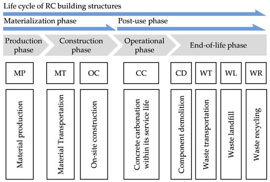
Figure 1.
System boundary for the carbon emission assessment of RC structures.
Based on the above system boundary, life cycle carbon emissions and costs of RC structural components can be calculated as
where E is the life cycle carbon emissions during the entire life cycle; Emat is the carbon emissions in the materialization phase; Euse is the CO2 absorption by concrete carbonization in the operational phase; Eend is the carbon emissions in the end-of-life phase. C is the life cycle cost; Cmat, Cuse, and Cend are the construction, operation, and demolition cost, respectively.
2.2. Carbon Emission Assessment
2.2.1. Materialization Phase
The construction of RC structures and components usually involves three fundamental subprojects encompassing concrete curing, steel processing, and formwork manufacturing. The specific requirements for each subproject can be determined based on construction and machinery quotas, which provide primary materials, auxiliary materials, and construction energy use. By incorporating the corresponding carbon emission factors of materials and energy, the integrated carbon emission coefficient of per unit subproject can be evaluated []. Consequently, carbon emissions in the materialization phase can be expressed as
where Qc, Qs, and Qf represent the engineering quantities of concrete, steel, and formwork subprojects, respectively; and ec, es, and ef denote the integrated carbon emission coefficients for the corresponding subprojects.
2.2.2. Operational Phase
In the operational phase, the CO2 absorbed through the concrete carbonization process [] can be estimated based on the following two major factors: (1) the volume of carbonated concrete, which is assessed based on the exposed surface area and the depth of carbonization []; and (2) the total amount of substances per unit volume of concrete which can chemically react with CO2 []. Based on the model of carbonization process proposed by Zhang and Jiang [], this study estimated the CO2 absorption as
where RH is the relative humidity; W/C is the water-to-cement ratio; mc is the cement content per unit volume of concrete; V0 is the volume fraction of CO2 in the air; t is the time period; S is the exposed surface area of the concrete component; is the amount of reactive substances per unit volume of concrete; and is the CO2 absorbed by unit mass of substances.
2.2.3. End-of-Life Phase
Carbon emissions associated with the end-of-life phase can be calculated as
where Ecd, Ewt, and Ewl represent the carbon emissions from component demolition, waste transportation, and waste landfill, respectively, and Ewr represents the potential carbon offsets from recycling materials.
For RC structural component demolition, carbon emissions from the removal and crushing can be evaluated as
where Qcd is the weight of structural components and EFcd is the carbon emission factor for the demolition of components per unit weight.
For carbon emissions from waste transportation, two main processes are considered: (1) the transportation of recyclable waste to recycling facilities, and (2) the transportation of non-recyclable waste to landfill sites. Accordingly, the corresponding carbon emissions can be estimated as
where Qwr,i and dwr,i are the quantity and transport distance of type i waste material that can be recycled, respectively; Qwl,i and dwl,i are the quantity and transport distance of type i waste material that required landfilling, respectively; and EFt is the carbon emission factor of transportation.
With respect to RC components, the quantities of waste concrete and steel designated for recycling and landfill can be calculated as
where Qi is the quantity of type i material consumed during the materialization phase; ηi is the loss rate of type i material during the removal and crushing processes; and μi is the recycling rate of type i material. For structural materials encompassing concrete and steel bars, the corresponding recycling rates were taken as 50% and 30%, respectively [].
For the landfill of waste materials, relevant carbon emissions were mainly sourced from the fuel consumption of machinery, which can be evaluated as
where qe represents the fuel consumption for landfilling per unit weight of waste materials (kg/t), and EFe is the carbon emission factor of the fuel.
Moreover, this study considered the carbon offsets relevant to the recycling and reuse of waste concrete and steel bars. As primary structural materials, promoting their recycling rates can significantly reduce carbon emissions. Generally, waste concrete can be processed into recycled aggregate, and waste steel can be melted down and reprocessed into new steel. The potential carbon offsets are estimated as
where Qrc and Qrs are the weight of recycled aggregate and steel, respectively; EFrc and EFrs represent the carbon offset potentials of recycled aggregate and steel, respectively, which can be evaluated as the differences between the emission factors of manufacturing primary and recycled materials []. The emission factors of recycled aggregate and steel were taken as 1.5 kg CO2e/t and 0.48 kg CO2e/t [,].
2.3. Life Cycle Cost Assessment
Life cycle costs of RC building structures can be assessed according to the defined system boundary, which encompasses the materialization, operational, and end-of-life phases. In the materialization phase, the construction cost of each subproject is sourced from labor, materials, machinery, as well as taxes and fees. Using the pricing method based on bills of quantities, the cost can be evaluated by integrating the quantities of individual subprojects with their corresponding prices as
where pc, ps, and pf represent the comprehensive prices of concrete, steel, and formwork subprojects, respectively.
For the operational phase, the costs of building structures primarily originate from maintenance and safety monitoring. However, the service lifespan of structural components, such as beams and columns, is generally expected to align with that of the entire building. Moreover, expensive monitoring measures are usually unnecessary for typical building structural components. Hence, the operational cost (Cuse) of structural components was not considered in this study.
In the end-of-life phase, the associated cost can be divided into four parts, corresponding to the classification of carbon emissions. Hence, the cost can be expressed as
where Ccd, Cwt, and Cwl represent the costs of component demolition, waste transportation, and waste landfill, respectively; Cwr represents the potential monetary benefits of waste material recycling; r is the discount rate of future cost; and T is the service lifespan of RC components.
The cost of demolishing components is determined based on the price of demolition work, which can be determined according to the local market or construction quota. It can be calculated as
where Vcom is the volume of RC components, and pcd is the price of demolition work.
The waste transportation cost is estimated based on the weight of materials, transport distance, and transport price per kilometer as
where qt,i represents the price of transporting waste materials.
The landfilling cost comprises both fixed and variable components. Fixed costs mainly refer to the capital investment for landfill construction, which is considered as depreciation fees. Variable costs refer to the operational and maintenance expenses during the landfill process. Accordingly, the landfilling cost can be estimated as
where pv,i and pf,i represent the fixed and variable prices for landfilling per unit weight of waste materials, respectively.
The recycling prices of waste materials usually fluctuate due to various factors, including material composition, local market demand, and processing fees. For waste concrete, the price is mainly affected by the level of crushing, the potential for utilizing recycled aggregates, and the cost of impurity removal. In contrast, steel products are highly recyclable, and their recycling prices are typically affected by the current scrap steel market rates. The total recycling benefits, in terms of monetary values, can be calculated as
where pwr,i represents the recycling price of type i waste material.
2.4. Design Constraints
In the optimization design of RC components, the constraints were determined in accordance with the Chinese code for design of concrete structures (GB/T 50010-2010) []. Generally, design constraints include (1) strength requirements, which encompass bending, shear, and compression resistance to ensure structural safety; (2) stiffness requirements, which ensure that the deflections and cracks remain within the limits; (3) durability requirements, which ensure sufficient structural reliability throughout the designed service life, despite potential structural deterioration; and (4) construction details such as limits of cross-sectional dimensions, as well as ratio and arrangement of reinforcements.
To achieve life cycle structural design that incorporates the above constraints, a reliability index-based design approach was adopted, in contrast to the conventional partial coefficient design method. According to the Chinese unified standard for reliability design of building structures (GB 50068-2018) [] for ductile and brittle failures in general structural components, the reliability index (β) under persistent design conditions in the ultimate limit state should exceed 3.2 and 3.7, respectively. Hence, a threshold of 3.2 was considered for bending and compressive damage, and a threshold of 3.7 was considered for shear damage.
2.5. Structural Deterioration and Uncertain Parameters
RC components deteriorate over time, which negatively affects their dynamic reliability. Understanding this deterioration process and predicting its progression are critical for effective life cycle design []. Previous research [] has shown that concrete carbonization and chloride-induced steel corrosion are the primary causes of the deterioration. Based on the experimental data obtained through sampling tests [], the time-varying compressive strength of concrete is inherently stochastic. This study adopted a polynomial model proposed by Gao et al. [] to describe the strength change over time as
where ηc(t) is the relative compressive strength at time t, and t is the elapsed service time of concrete components.
Comparatively, the changes in both the areas and strengths of steel bars caused by corrosion need to be considered in RC structures. The time at which the steel bars begin to corrode can be estimated with consideration of factors such as carbonization rate, concrete cover depth, and environmental conditions. Based on the Chinese standard for appraisal of reliability of civil buildings (GB 50292-2015) [], this time can be estimated as
where tᵢ is the time from construction completion to the initiation of steel corrosion; ψv, ψc, and ψₘ are the influencing coefficients of carbonization rate, concrete cover depth, and local environmental conditions, respectively.
As indicated above, there are multiple factors that can affect the corrosion of steel bars in RC structures. Taking the assumption of uniform corrosion [], the time-dependent diameter of corroded steel reinforcements can be evaluated as
where d(t) is the diameter of corroded steel bars at time t; d is the initial diameter of steel bars; and icorr(t) denotes the corrosion current density of the reinforcements [].
The yield strength of corroded reinforcements has a proportional relationship with that of uncorroded reinforcement [], which can be expressed as
where fys is the yield strength of corroded reinforcements; fy is the yield strength of uncorroded reinforcements; η is the cross-sectional loss ratio of the corroded reinforcements, which is related to d(t); and α is a regression coefficient.
Based on the above equations, the following parameters were considered for the deterioration of materials in this study: (1) concrete, including time-varying compressive strength, concrete cover depth, and carbonation rate; (2) steel bars, including diameter, corrosion current density, and cross-sectional loss ratio; and (3) local environmental conditions. Moreover, various uncertain factors that affect the structural capacities and load effects need to be incorporated into the assessment of time-varying reliability indices. In this study, five types of uncertain factors are considered, including loads, strengths of concrete and steel bars, geometric dimensions, and calculation modes for flexural, compressive, and shearing components. Based on the Chinese design code (GB/T 50010-2010) [] and Ref. [], Table 1 summarizes the statistical descriptions of these uncertain factors.

Table 1.
Statistical parameters of uncertainties.
2.6. Machine Learning-Based Surrogate Model
Monte Carlo simulation (MCS) is a widely adopted approach for calculating reliability indices of RC structures []. However, simulation runs on the order of 105 or more are typically required to maintain stable estimations of failure probability, which leads to a significant computational burden. Although several simulation-based alternatives, such as importance sampling, have been developed to improve the efficiency of MCS, computational cost remains a major challenge in the reliability analysis. Additionally, approximate analytical methods, including the first-order second-moment method [], are also popular in calculating engineering reliability. Nevertheless, their accuracy can be difficult to guarantee in highly nonlinear and non-differentiable problems. To balance the incorporation of uncertain factors and the efficiency of optimization design, this study employed a machine learning-based surrogate model to effectively approximate reliability indices of RC structural components. Figure 2 illustrates the framework of the surrogate model.
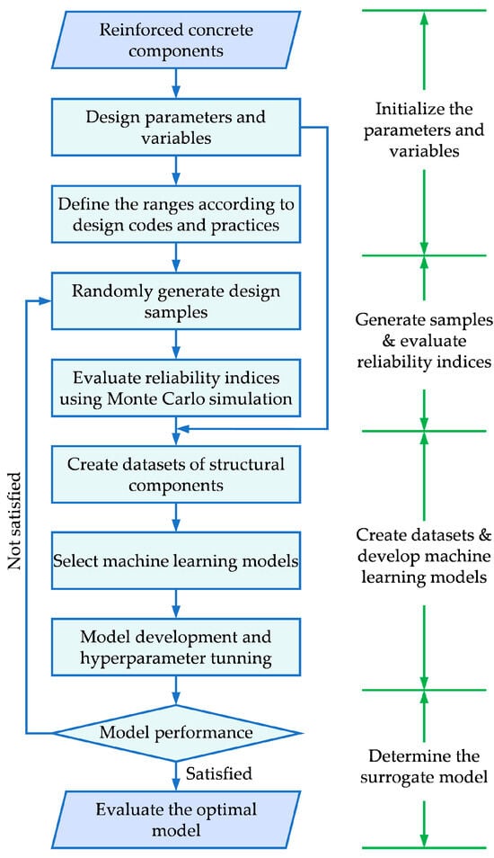
Figure 2.
Framework for developing the surrogate model.
This study used design parameters and load conditions as input features for developing machine learning models. The design parameters included cross-sectional dimensions, strength of materials, diameter and number of main bars, and diameter and spacing of stirrups. The load conditions incorporated live and dead loads for the beams, and axial forces and moments for the columns. Specifically, within defined ranges of discrete design parameters, RC component samples were randomly generated, and the reliability index of each sample during its service life was evaluated using the MCS approach. Subsequently, these samples were used to establish a dataset for developing machine learning models that can predict the reliability indices. Considering that no single algorithm excels in all problems, six alternative algorithms, encompassing polynomial regression (PR), support vector regression (SVR), extreme gradient boosting (XGBoost), Random Forest (RF), light gradient boosting machine (LightGBM), and back propagation neural networks (BPNN), were compared to capture the nonlinear relationship between design variables and reliability indices. Moreover, hyperparameter tuning was performed using Bayesian optimization, which leveraged prior knowledge to efficiently search for optimal settings []. A ten-fold cross-validation technique was applied to reduce the risk of overfitting in training the models, which ensured better generalization by averaging model performance across multiple data subsets. The models were developed using Python’s (v3.11.) scikit-learn library. Based on performance metrics including the coefficient of determination (R2), root mean squared error (RMSE), and mean absolute percentage error (MAPE), the best-performing model was determined as the surrogate model for evaluating reliability indices of structural components. The key steps for developing machine learning models are summarized as follows:
- (1)
- Preparing data and selected input features used for training models.
- (2)
- Splitting the data into training and testing sets, and standardizing the feature values.
- (3)
- Determining machine learning algorithms used for developing predictive models.
- (4)
- Tuning hyperparameters based on Bayesian optimization and cross-validation techniques.
- (5)
- Programming and training the models on the training set.
- (6)
- Assessing the model performance on the testing set.
- (7)
- Identifying the superior models according to the performance metrics.
Notably, parameters such as material strengths, dimensions, and loads of structural components strictly adhered to design codes, with their ranges reflecting typical engineering practices in generating samples and developing machine learning models. This strategy can ensure the applicability of the surrogate model and the subsequent optimization design, which prevents theoretical solutions from deflecting real-world scenarios due to unpractical parameter settings.
2.7. Hybrid Optimization Method
Figure 3 demonstrates the flowchart of the hybrid optimization approach. The bi-objective design optimization of a structural component involves the simultaneous optimization of two objective functions encompassing life cycle carbon emissions and costs defined in Section 2.2 and Section 2.3, while satisfying the reliability constraints and construction requirements as described in Section 2.4. Different optimization objectives typically have a conflicting relationship that their individual optima cannot be achieved simultaneously. In this context, determining the Pareto optimal solutions involves balancing the trade-offs between the two objectives using the Pareto front []. Within this front, no single solution is superior to the others across all objectives. Based on the Pareto front, this study employed the non-dominated sorting genetic algorithm (NSGA-II) for design optimization. Specifically, the time-varying resistance of a component, which incorporated structural deterioration and uncertain factors as defined in Section 2.5, was represented by the reliability index predicted using the surrogate model outlined in Section 2.6.
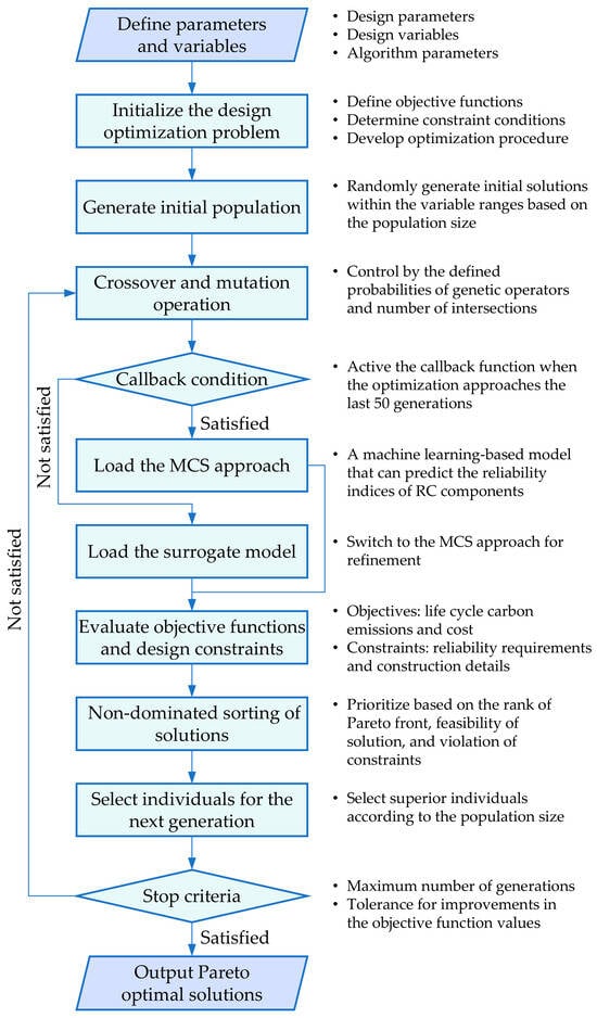
Figure 3.
Framework of the hybrid design optimization approach.
Notably, when the optimization approached the final stage, a callback function was activated to switch from the surrogate model to the MCS approach. In the early stages of the optimization, the surrogate model is used to accelerate the exploration and approximation of the feasible space. As the algorithm approaches convergence to the potential optimal regions, switching to the MCS approach ensures more accurate evaluations of the constraints. Consequently, this callback strategy is expected to avoid infeasible solutions caused by surrogate model errors in the final optima, and a threshold of 50 generations was set for switching based on trials and empirical judgment.
3. Case Study
3.1. Basic Information
To examine the feasibility and efficiency of the proposed life cycle sustainable design optimization approach, numerical examples of a beam and a column, as shown in Figure 4, were analyzed in this study. They served as typical examples of components in RC structures primarily subjected to bending and axial compression, respectively. The structural deterioration models and the distributions of uncertain parameters followed the descriptions provided in Section 2.5. Material prices were determined based on the market and construction quota, while the carbon emission factors of materials, energy, and transportation were obtained from Zhang and Zhang [].
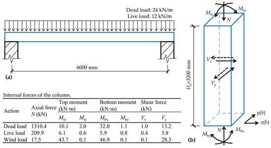
Figure 4.
Sketch of the numerical examples: (a) simply supported rectangular beam and (b) biaxially eccentric compressed column.
As shown in Figure 4a, a singly reinforced rectangular beam was considered, which was subjected to standard dead and live loads of 24 kN/m and 12 kN/m, respectively. In the initial manual design scheme, the strength grades of concrete section and steel bars were 30 MPa and 400 MPa, respectively, and the cross-sectional dimension was 200 mm × 600 mm. The corresponding total life cycle carbon emissions and cost were assessed as 540.2 kg CO2e and 1126.2 Chinese Yuan (CNY), respectively. As shown in Figure 4b, a biaxially eccentric compressed column was considered, which was subjected to designed dead, live, and wind loads. In the initial design scheme, the strength grades of concrete and steel bars were 30 MPa and 400 MPa, respectively, and the cross-sectional height and width were determined as 500 mm and 400 mm, respectively. The total life cycle carbon emissions and cost of the initial scheme were 354.9 kg CO2e and 709.6 CNY, respectively.
3.2. Parameter Setting
The design variables of RC components generally include material strength, cross-sectional dimension, reinforcement layout, and concrete cover depth. Based on the requirements of design codes and engineering practices, the values of those variables are discrete. Table 2 presents the specific domains of variables defined for the abovementioned numerical examples. These discrete ranges of design parameters were also used in developing machine learning models, given their broad applicability in engineering practice. Additionally, a wider range of load conditions was incorporated during model training to enhance their applicable scope. For the beam, the dead and live loads varied from 5 to 50 kN/m. For the column, the moment varied from 0 to 500 kN‧m, and the axial force varied from 0 to 5000 kN.

Table 2.
Ranges of design variables for the two numerical examples.
With respect to the algorithm parameters of NSGA-II, the number of design variables was determined as 10 for the beam and 12 for the column, respectively; the population size was taken as 100 to maintain the diversity of solutions; the probabilities for crossover and mutation operations were set as 0.9 and 0.1, respectively; and a maximum of 500 generations was considered.
4. Results and Discussion
4.1. Performance of the Surrogate Model
Based on the method proposed in Section 2.6, machine learning-based surrogate models were trained for predicting reliability indices of beams and columns at the end of the service life. The performance of models was compared using metrics encompassing R2, RMSE, and MAPE. As shown in Figure 5, the models based on the BPNN algorithm showed superior performance for both beams and columns. The corresponding values of R2 exceeded 0.95 on the testing datasets, and the MAPE values were below 6% for predicting the reliability of bending, compression, and shear resistance.
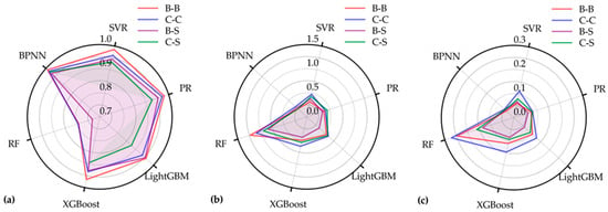
Figure 5.
Comparison of performance metrics among different machine learning-based surrogate models: (a) R2, (b) RMSE, and (c) MAPE. “B-B” and “B-S” represent bending and shear resistance of beams, respectively; “C-C” and “C-S” represent compression and shear resistance of columns, respectively.
Moreover, Figure 6 compares the predicted and actual reliability indices of samples based on the predictions of the optimal models, where the coordinates were filtered within the range from −5 to 5. It can be observed that the predictions lie around the ideal lines, indicating satisfactory accuracy. Notably, the machine learning models were developed to predict structural reliability indices across a wide range of values (approximately ±4.75), which was crucial due to the broad design space explored by the genetic algorithm. Additionally, the final optimal solutions were verified using the MCS approach to ensure compliance with reliability requirements set by the design codes. Nevertheless, the accuracy of predictions around the thresholds is critically important, as it can significantly influence the evolution strategies and outcomes of the optimization. Moreover, when reliability indices of samples are close to zero, the evaluation of percentage errors will become invalid. Hence, the above MAPEs of different models were compared by including samples whose reliability indices fell within a critical interval of ±1.0 from the thresholds as specified by the Chinese code (GB 50068-2018) [].
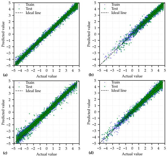
Figure 6.
Comparison between predicted and actual values of reliability indices for (a) bending resistance of beam; (b) shear resistance of beam; (c) compressive resistance of column; and (d) shear resistance of column.
Based on the superior BPNN models, Figure 7 demonstrates the results of the feature importance analysis. For both beams and columns, key factors encompassing load conditions, sectional height, and sectional width accounted for over 60% of the total feature contributions. For bending resistance of beams, number and diameter of main bars also played a significant role, while for compressive resistance of columns, concrete strength emerged as another key factor. Regarding shear resistance of members, the diameter of stirrups and concrete strength were also essential in explaining the models.
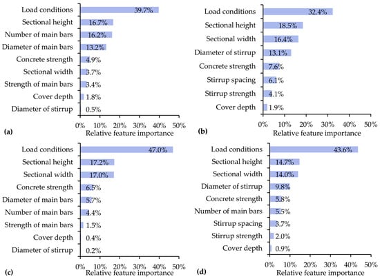
Figure 7.
Feature importance analysis of the BPNN models: (a) bending resistance of beam; (b) shear resistance of beam; (c) compressive resistance of column; and (d) shear resistance of column.
4.2. Results of the Optimization Design
Based on the hybrid optimization method, the numerical examples presented in Section 3 were analyzed. Table 3 summarizes the optimized design parameters of identified Pareto solutions. The minimum life cycle carbon emissions were 486.2 kg CO2e and 307.8 kg CO2e for the beam and column, respectively, while the minimum costs were 1016.1 CNY and 545.8 CNY, respectively. Compared to the initial design schemes, carbon emissions of the optimal solutions were reduced by 10.0% and 13.3%, respectively, while costs decreased by 9.8% and 23.1%. The optimization favored smaller cross-sections, thicker cover depth, and higher material strengths.

Table 3.
Design parameters of the optimal solutions.
Specifically, for the beam, the optimal solutions consistently adopted a cross-sectional width of 200 mm, with a height-to-width ratio of 2.75. For the column, the best life cycle sustainability was achieved when the concrete cover depth exceeded 45 mm, combined with the adaptation of relatively high-strength concrete. The results indicated that, while current design practices generally minimize the concrete cover depth to increase the effective sectional height, it is worth considering a significant increase in this depth to attain long-term structural durability in life cycle sustainable design. Moreover, compared to the MCS approach under the same computing environment, the integration of surrogate models reduced the computational time by 62.4–70.0%, with an average of approximately 2/3.
Based on the optimal design parameters of numerical examples, the composition of life cycle carbon emissions in solutions B1 and C1 was analyzed. As shown in Figure 8, the life cycle carbon emissions were lower than those of the materialization phase for both components, owing to nearly 7–13% carbon offsets during the operational and end-of-life phases. The concrete carbonization process captured 2.8–6.7% of the carbon emissions released by concrete production over a 50-year service life. The extent of carbon absorption was affected by the factors such as cover depth, strength, and composition of concrete. Meanwhile, recycling steel at a rate of 30% potentially offset 20% of the carbon emissions from steel consumption, contributing a 6–10% overall carbon reduction. In terms of material contributions, concrete was the major source of carbon emissions throughout the life cycle. However, steel also played a significant role, accounting for 43.1% and 24.7% of the carbon emissions from the beam and column, respectively. Formwork contributed a relatively small proportion of carbon emissions, which was less than 10% in both examples.

Figure 8.
Carbon emissions and material contribution rates at each stage of the life cycle: (a) beam and (b) column.
4.3. Parametric Analysis
To identify the impact of individual design variables on the optimal results, parametric analyses were conducted with respect to material strength and concrete cover depth. Moreover, two optimization approaches were considered to compare alternative system boundaries in sustainable structural design: (1) the approach proposed in this study, which incorporated life cycle carbon emissions and cost as objectives and employed the reliability index-based method; and (2) a simplified approach that incorporated carbon emissions and costs in the materialization phase as objectives and employed the partial coefficient design method. Notably, while bio-objective optimization was performed for the parametric analysis, the following subsections focus on comparing the minimum carbon emissions of the optimal solutions.
4.3.1. Concrete Strength
Figure 9 illustrates the changes in optimized carbon emissions corresponding to the variations in concrete strength. For the beam, carbon emissions exhibited an increase trend along with the strength grade. This can be attributed to the fact that increasing the concrete strength cannot significantly enhance bending resistance, while the associated carbon emission factor increases. However, a design using 30 MPa concrete yielded the minimum carbon emissions when considering the system boundary over the entire life cycle. Additionally, the optimal concrete strength may vary according to the changes in load effects, as suggested by previous studies []. For the column, a negative correlation was observed between carbon emissions and concrete strength, regardless of the defined system boundaries. This change occurred due to the applicability of smaller sectional dimensions in design scenarios involving high-strength concrete. Although the overall patterns of concrete strength on carbon emissions were consistent across both design approaches, optimal solutions need to be adapted to achieve life cycle carbon reduction.
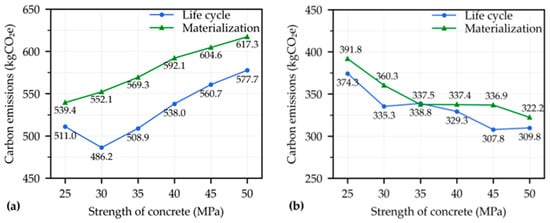
Figure 9.
Influence of concrete strength on optimized carbon emissions: (a) beam and (b) column.
4.3.2. Reinforcement Strength
Figure 10 illustrates the changes in optimized carbon emissions corresponding to the variations in the strength of longitudinal bars. For the beam, using high-strength longitudinal bars can reduce steel consumption by nearly 10% while achieving required bending resistance, thereby lowering carbon emissions in the design optimization from both the life cycle and materialization phase perspectives. Similar findings were also observed for the column, proving that the utilization of high-strength longitudinal bars can contribute to carbon reduction. Notably, the column examined in this study was subjected to relatively low eccentric bending moments, and the ratio of longitudinal bars was not significantly changed during optimization, despite variations in bar strength. Consequently, the corresponding decrease in carbon emissions was relatively minimal.
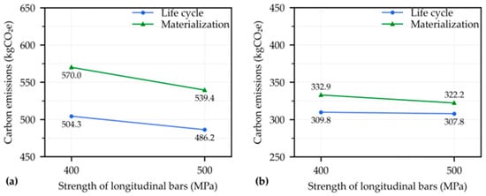
Figure 10.
Influence of longitudinal bar strength on optimized carbon emissions: (a) beam and (b) column.
Figure 11 illustrates the changes in optimized carbon emissions corresponding to variations in the strength of stirrups. For both components, the carbon emissions remained almost constant when the strength of stirrups changed. This can be attributed to the fact that the quantity of stirrups was determined according to the requirements of minimum ratio of stirrups in Chinese codes, rather than their shear resistance. Hence, the relatively low shear forces in the two examples were not dominant factors in determining structural reliability. Moreover, for stirrups with strength grades of 400 MPa and 500 MPa, the design strength specified in the Chinese codes remained fixed at 360 MPa. As a result, the carbon emissions associated with designs incorporating stirrups with a strength surpassing 400 MPa are expected to remain largely unaffected, even when subjected to higher shear forces.
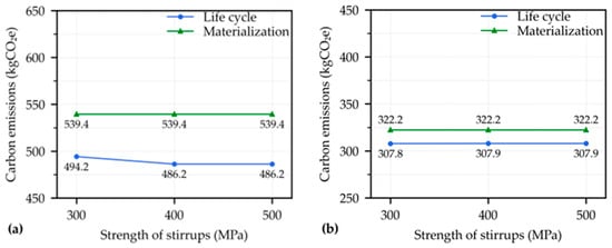
Figure 11.
Influence of stirrup strength on optimized carbon emissions: (a) beam and (b) column.
4.3.3. Concrete Cover Depth
Figure 12 illustrates the changes in optimized carbon emissions as the concrete cover depth increases. It was found that the trends of the optimal results varied when different system boundaries were used. Based on the simplified optimization within the materialization phase, embodied carbon emissions of the beam showed a positive correlation with concrete cover depth. This occurred because increasing the depth reduced the effective height of the section, which led to an increase in longitudinal reinforcements. For the column, carbon emissions showed minimal decreases when the concrete cover depth ranged from 20 mm to 45 mm, but increased when the cover depth reached 50 mm. Further analysis revealed that the compressive resistance of the column example was primarily influenced by the area of the concrete section, rather than steel reinforcements. An increase in cover depth led to a reduction in stirrup perimeter, which in turn contributed to a slight decrease in carbon emissions.
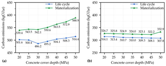
Figure 12.
Influence of concrete cover depth on optimized carbon emissions: (a) beam and (b) column.
In terms of life cycle design optimization, the carbon emissions showed a decreasing trend with an increasing concrete cover depth for the column, as thicker cover depth can help mitigate reinforcement corrosion. Comparatively, for the beam, carbon emissions decreased first, and then slightly increased when the concrete cover depth exceeded 30 mm. The potential reason for the different trends can be attributed to the fact that while a reduction in effective height does not significantly lower the resistance of a column subjected to relatively low eccentric compression, it can have considerable impact on the bending resistance of a typical beam. Consequently, the combined effects on structural durability and effective height led to different patterns in the changes in optimal design solutions. Generally, life cycle design preferred the utilization of thicker concrete cover depths to achieve superior long-term performance.
4.3.4. Comparison with Previous Studies
A comparison of the above results with previous research on sustainable design optimization reveals both consistent trends and unique contributions of this study. Several studies have underlined the importance of optimizing material strength and cross-sectional dimensions to enhance sustainability. For instance, Zhang and Zhang [] optimized singly and doubly reinforced beams, and their results aligned with this study, showing that increasing steel strength and minimizing sectional width effectively reduced embodied carbon and costs. Pierott et al. [] underscored the impact of detailed design decisions on reinforcement arrangements, which led to a cost reduction of more than 17% for a case beam. Investigation of columns by Mergos [] and Park et al. [] supported that improving enhancing material strengths led to greater reductions in both environmental and cost impacts, compared to simply increasing material quantities. However, Yücel et al. [] suggested that high-strength concrete may not always be effective in reducing carbon emissions and costs for beams. The sustainable design strategies can vary significantly depending on the specific structural components and design conditions. While the findings of this study are consistent with the broader conclusions from previous research, earlier studies have primarily focused on embodied carbon and costs. Comparatively, this study extends the scope of optimization by exploring life cycle sustainable design options that explicitly account for the structural deterioration over time.
5. Conclusions
This study developed a hybrid optimization approach for the life cycle sustainable design of RC components. By integrating the NSGA-II algorithm with machine learning models using a holistic life cycle system boundary, the proposed approach effectively balanced carbon emissions and costs in bio-objective design optimization, while ensuring long-term structural reliability. A case study of a singly reinforced beam and an eccentrically compressed column yielded the following key findings:
- (1)
- The proposed machine learning models demonstrated high accuracy in predicting reliability indices, with R2 values exceeding 0.95 and MAPEs below 6% on the testing sets. The incorporation of machine learning models reduced the algorithm’s runtime by approximately 2/3 compared to the conventional MCS approach, enabling more efficient life cycle design optimization.
- (2)
- The Pareto sets showed that the minimum carbon emissions for the case beam and column were 486.2 kgCO2e and 307.8 kgCO2e, respectively, with corresponding minimum costs of 1037.0 CNY and 545.8 CNY. The results validated the effectiveness of the proposed approach, achieving a carbon reduction of over 10% compared to the initial manual design.
- (3)
- A comparison of optimization results between the reliability index-based method and typical partial coefficient design method indicated that different strategies were required for life cycle sustainable design, considering structural deterioration and uncertainties. While the trends in optimized carbon emissions by varying material strengths were generally consistent across both methods, the optimized concrete cover depth differed. A thicker cover was preferred to mitigate carbon emissions in life cycle design.
Overall, this study established a collaborative approach that incorporated intelligent optimization and machine learning algorithms. The results of optimization and comparison among different methods contribute to an in-depth understanding of sustainable design for reinforced concrete components from a life cycle perspective. However, certain limitations should be acknowledged. First, the proposed approach was validated through numerical examples of a beam and a column. Further investigations can explore different design conditions (such as varying loads and environmental factors) as well as other types of structural components. Second, this study developed machine learning-based surrogate models to evaluate structural reliability. Given their high computational efficiency, it can be valuable to further integrate these models into the sustainable design optimization of more complex structures beyond individual components. Finally, while the methodological framework proposed in this study can be applied to a wider range of structural members, the case study results are specific to the Chinese context. These results may vary across regions with different labor costs and material recycling systems, and therefore, further exploration is needed.
Author Contributions
Conceptualization, X.Z.; methodology, X.Z.; software, X.Z. and J.Z.; validation, J.Z.; formal analysis, X.Z. and J.Z.; investigation, X.Z. and J.Z.; resources, J.Z.; data curation, J.Z.; writing—original draft preparation, X.Z. and J.Z.; writing—review and editing, X.Z.; visualization, X.Z. and J.Z.; supervision, X.Z.; project administration, X.Z.; funding acquisition, X.Z. All authors have read and agreed to the published version of the manuscript.
Funding
This research was funded by National Natural Science Foundation of China (52578211).
Institutional Review Board Statement
Not applicable.
Informed Consent Statement
Not applicable.
Data Availability Statement
Research data have been introduced in the published article. Additional research data are available by contacting the corresponding author on reasonable requests.
Conflicts of Interest
The authors declare no conflicts of interest.
Abbreviations
| BPNN | Back propagation neural networks |
| CNY | Chinese Yuan |
| LCA | Life cycle assessment |
| LightGBM | Light gradient boosting machine |
| MAPE | Mean absolute percentage error |
| MCS | Monte Carlo simulation |
| NSGA-II | Non-dominated sorting genetic algorithm |
| PR | Polynomial regression |
| PSO | Particle swarm optimization |
| R2 | Coefficient of determination |
| RC | Reinforced concrete |
| RF | Random Forest |
| RMSE | Root mean squared error |
| SVR | Support vector regression |
| XGBoost | Extreme gradient boosting |
References
- Poorisat, T.; Aigwi, I.E.; Doan, D.T.; GhaffarianHoseini, A. Unlocking the potentials of sustainable building designs and practices: A Systematic Review. Build. Environ. 2024, 266, 112069. [Google Scholar] [CrossRef]
- Chen, T.; Zhang, N.; Ye, Z.; Jiang, K.; Lin, Z.; Zhang, H.; Xu, Y.; Liu, Q.; Huang, H. Carbon reduction benefits of photovoltaic-green roofs and their climate change mitigation potential: A case study of Xiamen city. Sustain. Cities Soc. 2024, 114, 105760. [Google Scholar] [CrossRef]
- Govindarajan, L.; Batcha, M.F.B.M.; Abdullah, M.K.B. Solar energy policies in southeast Asia towards low carbon emission: A review. Heliyon 2023, 9, e14294. [Google Scholar] [CrossRef] [PubMed]
- Abass, P.J.; Muthulingam, S. Comprehensive assessment of PCM integrated roof for passive building design: A study in energo-economics. Energy Build. 2024, 317, 114387. [Google Scholar] [CrossRef]
- Liang, Y.; Pan, Y.; Yuan, X.; Yang, Y.; Fu, L.; Li, J.; Sun, T.; Huang, Z.; Kosonen, R. Assessment of operational carbon emission reduction of energy conservation measures for commercial buildings: Model development. Energy Build. 2022, 268, 112189. [Google Scholar] [CrossRef]
- Chen, R.; Tsay, Y.; Zhang, T. A multi-objective optimization strategy for building carbon emission from the whole life cycle perspective. Energy 2023, 262, 125373. [Google Scholar] [CrossRef]
- Falana, J.; Osei-Kyei, R.; Tam, V.W.Y. Towards achieving a net zero carbon building: A review of key stakeholders and their roles in net zero carbon building whole life cycle. J. Build. Eng. 2024, 82, 108223. [Google Scholar] [CrossRef]
- Feng, H.; Zhao, J.; Zhang, H.; Zhu, S.; Li, D.; Thurairajah, N. Uncertainties in whole-building life cycle assessment: A systematic review. J. Build. Eng. 2022, 50, 104191. [Google Scholar] [CrossRef]
- Wang, X.; Teigland, R.; Hollberg, A. Identifying influential architectural design variables for early-stage building sustainability optimization. Build. Environ. 2024, 252, 111295. [Google Scholar] [CrossRef]
- Cang, Y.; Yang, L.; Luo, Z.; Zhang, N. Prediction of embodied carbon emissions from residential buildings with different structural forms. Sust. Cities Soc. 2020, 54, 101946. [Google Scholar] [CrossRef]
- Tian, Y.; Chai, K. Building design and operation multi-objective optimization: Energy costs vs. emissions. Energy Build. 2025, 329, 115225. [Google Scholar] [CrossRef]
- Qin, S.; Guan, H.; Liao, W.; Gu, Y.; Zheng, Z.; Xue, H.; Lu, X. Intelligent design and optimization system for shear wall structures based on large language models and generative artificial intelligence. J. Build. Eng. 2024, 95, 109996. [Google Scholar] [CrossRef]
- Negrin, I.; Kripka, M.; Yepes, V. Multi-criteria optimization for sustainability-based design of reinforced concrete frame buildings. J. Clean. Prod. 2023, 425, 139115. [Google Scholar] [CrossRef]
- Fraile-Garcia, E.; Ferreiro-Cabello, J.; Martinez-Camara, E.; Jimenez-Macias, E. Optimization based on life cycle analysis for reinforced concrete structures with one-way slabs. Eng. Struct. 2016, 109, 126–138. [Google Scholar] [CrossRef]
- Huang, X.; Jiao, Z.; Xing, F.; Sui, L.; Hu, B.; Zhou, Y. Performance assessment of LC3 concrete structures considering life-cycle cost and environmental impacts. J. Clean. Prod. 2024, 436, 140380. [Google Scholar] [CrossRef]
- Khalid, O.W.; Isa, N.A.M.; Sakim, H.A.M. Emperor penguin optimizer: A comprehensive review based on state-of-the-art meta-heuristic algorithms. Alex. Eng. J. 2023, 63, 487–526. [Google Scholar] [CrossRef]
- Röck, M.; Balouktsi, M.; Saade, M.R.M. Embodied carbon emissions of buildings and how to tame them. One Earth 2023, 6, 1458–1464. [Google Scholar] [CrossRef]
- Li, X.; Xie, W.; Xu, L.; Li, L.; Jim, C.Y.; Wei, T. Holistic life-cycle accounting of carbon emissions of prefabricated buildings using LCA and BIM. Energy Build. 2022, 266, 112136. [Google Scholar] [CrossRef]
- Seyedabadi, M.R.; Abolhassani, S.S.; Eicker, U. District cradle to grave LCA including the development of a localized embodied carbon database and a detailed end-of-life carbon emission workflow. J. Build. Eng. 2023, 76, 107101. [Google Scholar] [CrossRef]
- Hong, J.; Shen, G.Q.; Feng, Y.; Lau, W.S.; Mao, C. Greenhouse gas emissions during the construction phase of a building: A case study in China. J. Clean. Prod. 2015, 103, 249–259. [Google Scholar] [CrossRef]
- Teng, Y.; Pan, W. Estimating and minimizing embodied carbon of prefabricated high-rise residential buildings considering parameter, scenario and model uncertainties. Build. Environ. 2020, 180, 106951. [Google Scholar] [CrossRef]
- Ding, Z.; Liu, S.; Luo, L.; Liao, L. A building information modeling-based carbon emission measurement system for prefabricated residential buildings during the materialization phase. J. Clean. Prod. 2020, 264, 121728. [Google Scholar] [CrossRef]
- Zhang, X.; Wang, F. Influence of parameter uncertainty on the low-carbon design optimization of reinforced concrete continuous beams. Struct. Concr. 2023, 24, 855–871. [Google Scholar] [CrossRef]
- Zhang, X.; Zhang, X. Sustainable design of reinforced concrete structural members using embodied carbon emission and cost optimization. J. Build. Eng. 2021, 44, 102940. [Google Scholar] [CrossRef]
- Mergos, P.E. Contribution to sustainable seismic design of reinforced concrete members through embodied CO2 emissions optimization. Struct. Concr. 2018, 19, 454–462. [Google Scholar] [CrossRef]
- Park, H.S.; Lee, H.; Kim, Y.; Hong, T.; Choi, S.W. Evaluation of the influence of design factors on the CO2 emissions and costs of reinforced concrete columns. Energy Build. 2014, 82, 378–384. [Google Scholar] [CrossRef]
- Hussain, K.; Salleh, M.N.M.; Cheng, S.; Shi, Y. Metaheuristic research: A comprehensive survey. Artif. Intell. Rev. 2019, 52, 2191–2233. [Google Scholar] [CrossRef]
- Khajehzadeh, M.; Iraji, A.; Majdi, A.; Keawsawasvong, S.; Nehdi, M.L. Adaptive salp swarm algorithm for optimization of geotechnical structures. Appl. Sci. 2022, 12, 6749. [Google Scholar] [CrossRef]
- Kashani, A.R.; Camp, C.V.; Akhani, M.; Ebrahimi, S. Optimum design of combined footings using swarm intelligence-based algorithms. Adv. Eng. Softw. 2022, 169, 103140. [Google Scholar] [CrossRef]
- Tunca, O.; Çarbaş, S. Minimum weight design of reinforced concrete beams utilizing grey wolf and backtracking search optimization algorithms. Chall. J. Concr. Res. Let. 2022, 13, 72–79. [Google Scholar] [CrossRef]
- Pierott, R.; Hammad, A.W.A.; Haddad, A.; Garcia, S.; Falcón, G. A mathematical optimisation model for the design and detailing of reinforced concrete beams. Eng. Struct. 2021, 245, 112861. [Google Scholar] [CrossRef]
- Xu, C.; Liu, J.; Wu, Z.; Chen, Y.F. Automated steel reinforcement detailing in reinforced concrete frames using evolutionary optimization and artificial potential field. Automat. Constr. 2022, 138, 104224. [Google Scholar] [CrossRef]
- Yücel, M.; Nigdeli, S.M.; Bekdaş, G. Generation of sustainable models with multi-objective optimum design of reinforced concrete (RC) structures. Structures 2022, 40, 223–236. [Google Scholar] [CrossRef]
- Kripka, M.; Medeiros, G.F. Cross-sectional optimization of reinforced concrete columns considering both economical and environmental costs. In Proceedings of the International Conference on Green Building, Materials and Civil Engineering, Sanya, China, 22–23 August 2012; pp. 1086–1089. [Google Scholar]
- Medeiros, G.F.; Kripka, M. Optimization of reinforced concrete columns according to different environmental impact assessment parameters. Eng. Struct. 2014, 59, 185–194. [Google Scholar] [CrossRef]
- Sánchez-Olivares, G.; Tomás, A. Improvements in meta-heuristic algorithms for minimum cost design of reinforced concrete rectangular sections under compression and biaxial bending. Eng. Struct. 2017, 130, 162–179. [Google Scholar] [CrossRef]
- Vaez, S.R.H.; Qomi, H.S. Bar layout and weight optimization of special RC shear wall. Structures 2018, 14, 153–163. [Google Scholar] [CrossRef]
- Sangngamratsakul, N.; Kubaha, K.; Chiarakorn, S. Embodied energy coefficient quantification and implementation for an energy-conservative house in Thailand. Sustainability 2024, 16, 4045. [Google Scholar] [CrossRef]
- Asare, G.O.; Barnett, S.; Awinda, K.; Martinson, B. Life cycle assessment of steel fibre-reinforced concrete beams. Cogent Eng. 2024, 11, 2374942. [Google Scholar] [CrossRef]
- Zhang, X.; Zhang, X. A subproject-based quota approach for life cycle carbon assessment at the building design and construction stage in China. Build. Environ. 2020, 185, 107258. [Google Scholar] [CrossRef]
- Medvedev, V.; Pustovgar, A. A review of concrete carbonation and approaches to its research under irradiation. Buildings 2023, 13, 1998. [Google Scholar] [CrossRef]
- Zhang, Y.; Jiang, L.X. A practical mathematical model of concrete carbonation depth based on carbonation mechanism. Ind. Build. 1998, 1, 16–19. (In Chinese) [Google Scholar]
- Pade, C.; Guimaraes, M. The CO2 uptake of concrete in a 100 year perspective. Cem. Concr. Res. 2007, 37, 1348–1356. [Google Scholar] [CrossRef]
- Kong, M.; Ji, C.; Hong, T.; Kang, H. Impact of the use of recycled materials on the energy conservation and energy transition of buildings using life cycle assessment: A case study in South Korea. Renew. Sust. Energ. Rev. 2022, 155, 111891. [Google Scholar] [CrossRef]
- Zhao, Q.; Gao, W.; Su, Y.; Wang, T.; Wang, J. How can C&D waste recycling do a carbon emission contribution for construction industry in Japan city? Energy Build. 2023, 298, 113538. [Google Scholar] [CrossRef]
- Liu, K.; Zheng, J.; Dong, S.; Xie, W.; Zhang, X. Mixture optimization of mechanical, economical, and environmental objectives for sustainable recycled aggregate concrete based on machine learning and metaheuristic algorithms. J. Build. Eng. 2023, 63, 105570. [Google Scholar] [CrossRef]
- Zhang, X.; Li, Y.; Chen, H.; Yan, X.; Liu, K. Characteristics of embodied carbon emissions for high-rise building construction: A statistical study on 403 residential buildings in China. Resour. Conserv. Recycl. 2023, 198, 107200. [Google Scholar] [CrossRef]
- GB/T 50010-2010; Code for Design of Concrete Structures. China Architecture & Building Press: Beijing, China, 2024.
- GB 50068-2018; Unified Standard for Reliability Design of Building Structures. China Architecture & Building Press: Beijing, China, 2018.
- Val, D.V.; Andrade, C.; Sykora, M.; Stewart, M.G.; Bastidas-Arteaga, E.; Mlcoch, J.; Truong, Q.C.; El Soueidy, C.P. Probabilistic modelling of deterioration of reinforced concrete structures. Struct. Saf. 2025, 113, 102454. [Google Scholar] [CrossRef]
- Li, H.; Wu, X.; Nie, Q.; Yu, J.; Zhang, L.; Wang, Q.; Gao, Q. Lifetime prediction of damaged or cracked concrete structures: A review. Structures 2025, 71, 108095. [Google Scholar] [CrossRef]
- Gao, X.; Li, J.; Ren, X. Probabilistic model for long-term time-dependent compressive strength of concrete in existing buildings. J. Perform. Constr. Facil. 2018, 32, 115157619. [Google Scholar] [CrossRef]
- Gao, X.; Yan, Y.; Li, L. Change law of time-dependent concrete compressive strength in the atmospheric environment. China Civ. Eng. J. 2015, 48, 19–26. (In Chinese) [Google Scholar] [CrossRef]
- GB 50292-2015; Standard for Appraisal of Reliability of Civil Buildings. China Architecture & Building Press: Beijing, China, 2016.
- Stewart, M.G.; Rosowsky, D.V. Time-dependent reliability of deteriorating reinforced concrete bridge decks. Struct. Saf. 1998, 20, 91–109. [Google Scholar] [CrossRef]
- Vu, K.A.T.; Stewart, M.G. Structural reliability of concrete bridges including improved chloride-induced corrosion models. Struct. Saf. 2000, 22, 313–333. [Google Scholar] [CrossRef]
- Fang, L.; Zhou, Y.; Yi, D.; Yi, W. Experimental study on flexural capacity of corroded RC slabs reinforced with basalt fiber textile. Appl. Sci. 2021, 11, 144. [Google Scholar] [CrossRef]
- Gong, J.; Zhang, Q. Principles of Reliability Design for Engineering Structures; China Machine Press: Beijing, China, 2022. (In Chinese) [Google Scholar]
- Pradlwarter, H.J.; Schuëller, G.I.; Koutsourelakis, P.S.; Charmpis, D.C. Application of line sampling simulation method to reliability benchmark problems. Struct. Saf. 2007, 29, 208–221. [Google Scholar] [CrossRef]
- Yang, Z.; Ching, J. A novel reliability-based design method based on quantile-based first-order second-moment. Appl. Math. Model. 2020, 88, 461–473. [Google Scholar] [CrossRef]
- Zhang, X.; Chen, H.; Sun, J.; Zhang, X. Predictive models of embodied carbon emissions in building design phases: Machine learning approaches based on residential buildings in China. Build. Environ. 2024, 258, 111595. [Google Scholar] [CrossRef]
- Liu, Q.; Li, X.; Liu, H.; Guo, Z. Multi-objective metaheuristics for discrete optimization problems: A review of the state-of-the-art. Appl. Soft Comput. 2020, 93, 106382. [Google Scholar] [CrossRef]
Disclaimer/Publisher’s Note: The statements, opinions and data contained in all publications are solely those of the individual author(s) and contributor(s) and not of MDPI and/or the editor(s). MDPI and/or the editor(s) disclaim responsibility for any injury to people or property resulting from any ideas, methods, instructions or products referred to in the content. |
© 2025 by the authors. Licensee MDPI, Basel, Switzerland. This article is an open access article distributed under the terms and conditions of the Creative Commons Attribution (CC BY) license (https://creativecommons.org/licenses/by/4.0/).