Abstract
Intelligent crack detection and displacement measurement are critical for evaluating the health status of dams. Earth-fill dams, composed of fragmented independent material particles, are particularly vulnerable to climate changes that can exacerbate cracking and displacement. Existing crack segmentation methods often suffer from discontinuous crack segmentation and misidentification due to complex background noise. Furthermore, current skeleton line-based width measurement techniques demonstrate limited accuracy in processing complex crack patterns. To address these limitations, this study introduces a novel three-step approach for crack detection in earth-fill dams. Firstly, an enhanced YOLOv8-CGA crack segmentation method is proposed, incorporating a Cascaded Group Attention (CGA) mechanism into YOLOv8 to improve feature diversity and computational efficiency. Secondly, image processing techniques are applied to extract sub-pixel crack edges and skeletons from the segmented regions. Finally, an adaptive skeleton fitting algorithm is developed to achieve high-precision crack width estimation. This approach effectively integrates the pattern recognition capabilities of deep learning with the detailed delineation strengths of traditional image processing. Additionally, dam crest displacements and crack zone strain field are measured via the digital image correlation (DIC) method. The efficacy and robustness of the proposed method are validated through laboratory experiments on an earth-fill dam model, demonstrating its potential for practical structural health monitoring (SHM) applications in a changing climate.
1. Introduction
Earth-fill dams are typically formed by the placement and compaction of complex semi-plastic fills comprising various soil compositions. These dams are the most widely used due to their adaptability to diverse foundations, efficient use of construction materials, and cost-effectiveness [1,2]. However, climate change is intensifying the frequency and severity of extreme weather events, leading to increased risks of differential settlement, hydraulic fracturing, and seismic activity, which can result in inevitable cracks and displacements [3,4]. In older dams, these issues may be exacerbated by inadequate design, poor construction practices, and material defects. If cracks and deformations are allowed to develop without intervention, there is a significant risk of dam failure and incalculable damage. Therefore, crack detection and displacement measurement are crucial for the safe operation and informed management of earth-fill dams [5].
Current crack detection methodologies encompass digital imaging, laser scanning, infrared thermal imaging, acoustic emission, resistivity measurement, and geological radar [6,7,8,9]. The rapid advancement of digital image processing technology, digital image-based detection methods offering advantages such as non-destructive, ease of operation, intuitive results, and long-term tracking, showing great potential in dam crack detection [10]. These techniques utilize contrast, edge, and texture information, employing algorithms to accurately locate cracks and quantify their morphological characteristics. Image-based dam crack detection techniques can be categorized into traditional image processing and deep learning-based methods. Traditional methods are frequently susceptible to cope with changing lighting conditions and complex textures [11,12], consequently limiting their practical application in dam monitoring scenarios.
Recent advances in computational capabilities and big data technologies have catalyzed the application of deep learning in crack detection. Deep learning models demonstrate strong proficiency in analyzing the complexity of earth-fill dam surfaces, characterized by diverse textures and materials. These models effectively distinguish cracks from complex background textures inherent to dam surface, thereby reducing the dependence on extensive parameter tuning and computational resources typically required by conventional methods [13,14,15]. Furthermore, deep learning approaches exhibit adaptability to novel crack patterns through iterative training, enhancing segmentation accuracy and robustness under environment conditions.
Several studies have introduced convolutional neural networks (CNNs) and deep learning models to enhance segmentation accuracy and efficiency. Liu et al. proposed a deep hierarchical CNNs named DeepCrack for automatic crack detection in images, addressing the challenges of pixel-wise crack segmentation through an end-to-end approach [16]. Han et al. proposed a skip-level round-trip sampling block structure to construct a pixel-level semantic segmentation network, CrackW-Net, to address the misrecognition of traditional segmented CNNs [17]. Al-Huda et al. proposed a hybrid deep learning pavement crack segmentation method via the capability of the revised CAM strategy [18]. Lu et al. proposed a model based on YOLOv8s-YOLO-DEW combined with Unet for detecting and quantifying microcracks on the surface of concrete dams [19]. Chen et al. proposed a concrete dams crack segmentation network (DCST-net) based on a pure visual transformer using a modified Swin transformer block as the basic block [20].
For dam-specific applications, Huang et al. addressed the limitation of difficulty in collecting images of dam underwater cracks, generating underwater dam crack images through unsupervised image-to-image translation and existing above-water dam crack images [21]. Guo et al. proposed CrackWave R-CNN, an underwater dam crack detection model that fuses discrete wavelet transform and deep learning [22]. Zhu et al. combined deep semantic segmentation network and model hyperparameters optimization algorithm to proposed a data-intelligent perception method of dam underwater cracks, verified its effectiveness through the detection of cracks in a concrete-faced rockfill dam [23]. Li et al. proposed a technique for detecting dam underwater cracks by integrating the SwinTransformer module into the YOLOv5 model [24].
The literature reveals a predominant focus on leveraging CNNs and their variants to enhance the accuracy and efficiency of crack identification and localization. However, these studies primarily address crack detection on concrete surfaces, while monitoring techniques specifically tailored for earth-fill dams remain underdeveloped [25,26]. Compared to concrete dams, earth-fill dams present more background noise and unevenness of cracks [22]. Although existing studies based on improved CNNs show excellent crack segmentation for concrete dams, the crack intensity inhomogeneity, environmental complexity, and significant noise of earth-fill dams make accurate segmentation of cracks and noise still a challenge [27,28]. Furthermore, the quantitative calculation of crack width and displacement in earth-fill dams constitutes a critical task, holding substantial significance for the structural health assessment of dams.
This study investigates the application of computer vision technology for crack detection and displacement measurement in earth-fill dams. By incorporating the Cascade Group Attention (CGA) mechanism into YOLOv8, an improved YOLOv8-CGA crack segmentation method is developed. The segmentation performance is compared with commonly used models such as YOLOv5m, YOLOv7, and YOLOv8m to test accuracy. An improved skeleton line-based width calculation method is also proposed in this study. Furthermore, innovative use of digital image correlation methods is employed to measure the displacement of the dam crest.
2. Methodology
Figure 1 shows a flowchart of the proposed crack detection and displacement measurement method for earth-fill dams. For crack detection: (1) the YOLOv8-CGA model is trained and evaluated; (2) the optimized model conducts crack segmentation on the collected dam images; and (3) crack widths are quantified. For displacement measurement: (1) calibrate the imaging system to determine the pixel scale factor; (2) determine the pixel coordinates of the measurement points and track them in the sequence of images; and (3) calculate the displacement of each measurement point.

Figure 1.
Flowchart of the proposed crack detection and displacement measurement method for earth-fill dams.
2.1. Earth-Fill Dams Crack Detection
This study proposed a three-step method for high-accuracy earth-fill dam crack detection, as shown in Figure 2. First, the yolo v8-CGA method was developed for crack recognition and segmentation in the scene, which recognizes micro-cracks that are difficult to identify by existing methods. Second, the image is cropped according to the crack recognition results to retain only the rectangular region where the crack is located, and then the edge and skeleton line of the crack are extracted using image processing technology. Third, the width of the cracks was calculated using the identified crack edges and skeleton lines, and the developmental trends of the cracks were explored.
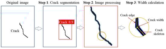
Figure 2.
Introduced 3-step method for crack segmentation and width calculation.
2.1.1. Crack Segmentation Based on Improved YOLOv8-CGA Method
YOLO is a single-stage deep learning algorithm known for its real-time data processing capabilities. Its architecture has undergone significant evolution, with major performance leaps in influential versions such as YOLOv3 [29]. Compared to previous models in the YOLO series, modifications have been made to the backbone architecture of YOLOv8 by replacing 6 × 6 convolutions with 3 × 3 convolutions in the initial convolutional layer and replacing all C3 modules with C2f modules, which showed significant improvements in segmentation speed and accuracy over earlier versions [30]. Therefore, an improved crack recognition algorithm for earth-fill dams based on the YOLOv8 framework is proposed in this study. However, existing feature extraction modules in YOLOv8 focus on extracting local features from input images. For cracks in the early stages of development, it is difficult for existing yolo v8 to achieve effective crack segmentation because the low-contrast crack features are potentially covered by complex background textures, especially for earth-fill dams. To address this limitation, this study introduced an improved YOLO v8-CGA crack segmentation method by introducing the Cascaded Group Attention (CGA) mechanism into YOLO v8.
- (1)
- Cascaded Group Attention
Cascaded Group Attention (CGA) is an innovative attention module designed to enhance model representation capabilities through structured feature processing [31,32]. Its core principle involves grouping input features along the channel dimension. Independent attention heads are then assigned to each feature subset. This approach ensures greater diversity in the features processed by each head, allowing the module to capture multiple aspects of the features comprehensively. Consequently, the CGA mechanism can show significant technical advantages for the challenge of difficult to effectively segmenting microcrack signals in complex backgrounds. As illustrated in Figure 3, when the CGA module processes the input features at layer i, it first divides them into h groups: . The j-th attention head specifically processes the corresponding input feature group The computation is represented as follows:
where the , , and are the dedicated projection matrices for the j-th head. signifies the standard self-attention computation, denotes concatenation along the channel dimension, and is the output projection matrix.

Figure 3.
Cascaded Group Attention (CGA) diagram.
Furthermore, CGA incorporates a cascading structure to facilitate information interaction across different heads. Starting from the second head, the input to each head ( > 1) integrates the output from the previous head ( − 1):
CGA grouped attention design enables individual attention heads to focus independently on different feature dimensions of the cracks, such as edge contours or textural characteristics. This capability aids in the precise separation and identification of fine cracks, even amidst noisy backgrounds. The cascading structure within CGA promotes hierarchical information transfer and progressive refinement within the multi-head attention network. By effectively fusing local crack details with broader contextual information, the mechanism enhances the model’s ability to perceive crack continuity and overall shape.
- (2)
- Network structure of YOLOv8-CGA
To improve the crack detection accuracy of the yolo v8 model for complex backgrounds, this study introduces the Cascaded Group Attention (CGA) mechanism into the YOLOv8 backbone. Specifically, the original C2f module is upgraded to a C2f_CGA structure. The proposed network structure of YOLOv8-CGA is shown in Figure 4, which consists of a Backbone, a Neck and a Head.
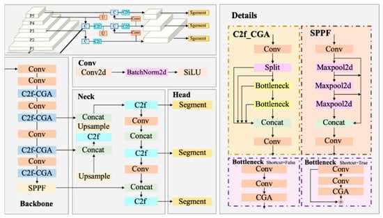
Figure 4.
Network structure of YOLOv8-CGA.
By enhancing feature selection and integration within the C2f module, the proposed C2f_CGA structure yields more discriminative feature representations. This significantly improves sensitivity to diverse crack features, especially micro-cracks. It establishes a more robust feature foundation for subsequent tasks of precise localization and segmentation, ultimately contributing to an overall enhancement in detection performance. These components work collaboratively to perform the entire process, from image data processing to instance segmentation output.
- (3)
- Evaluation Metrics
Evaluating the overall effectiveness of dam crack instance segmentation models requires considering both localization accuracy and contour delineation precision. This study selected mean Average Precision (mAP) as the key performance indicator. With special emphasis on mAP50, calculated at an Intersection over Union (IoU) threshold of 0.5. Results are reported mAP50 results separately for bounding boxes (mAP50_box) and segmentation masks (mAP50_mask). This allows for a comprehensive assessment of model performance. The evaluation involves TP (True Positives), FP (False Positives), and FN (False Negatives), representing correctly detected, incorrectly detected, and missed crack instances, respectively.
2.1.2. Crack Width Calculation
- (1)
- Crack edge and skeleton extraction
Images containing cracks are annotated using semantic segmentation, with bounding boxes precisely indicating the location of detected cracks. To refine segmentation and localize cracks accurately, traditional image processing techniques are employed to further analyze these initially identified areas. This step includes image denoising, threshold segmentation, edge segmentation, and morphological processing operations.
Bilateral filtering is advantageous for this study as it not only reduces noise but also preserves edge details, which is critical for maintaining the integrity of crack edges in the images [33]. It can be expressed as:
and the normalization term, , is defined as
where is the filtered image, I is the original input image to be filtered, x are the coordinates of the current pixel to be filtered, is the window centered in x, is the range kernel for smoothing differences in intensities, and is the spatial kernel for smoothing differences in coordinates.
Otsu’s method is utilized to segment the denoised image, effectively distinguishing between crack areas and the background based on grayscale intensity distributions [34]. It is a globally optimal thresholding technique that selects the threshold to minimize the intra-class variance of black and white pixels, thereby differentiating between cracks and background. The algorithm exhaustively searches for the threshold that minimizes the intra-class variance, defined as a weighted sum of variances of the two classes:
where weights and are the probabilities of the two classes separated by a threshold t, and and are variances of these two classes. Morphological operations, shape-based image processing techniques, are employed to enhance the visibility of cracks by removing noise and small irrelevant objects that might have been misclassified as cracks during the segmentation phase. These operations, specifically opening and closing, help connect fragmented crack segments, ensuring a more continuous and accurate representation of crack patterns.
Crack edges and skeletons are crucial for estimating crack parameters. As illustrated in Figure 5, skeletonization is a technique for extracting the centerline of a graphic or image. It simplifies complex shapes into lines with a width of a single pixel, reflecting the basic framework of the image by iteratively removing pixels at the object’s edge. In this study, the Medial Axis Transform (MAT) proposed is employed due to its ability to reconstruct the original shape [35]. To ensure a clean and topologically stable skeleton, several refinement steps were applied after crack segmentation. The binary crack image was first smoothed using a Gaussian filter and processed with morphological opening to remove isolated noise pixels. The skeleton was then extracted using a topology-preserving thinning algorithm rather than a simple dilation–erosion process. Short spurious branches were removed through morphological pruning, and the final skeleton was smoothed using a centerline fitting algorithm to maintain continuity and suppress burrs. The edges of the cracks can be detected on the segmented image using the Canny edge detection algorithm [36].

Figure 5.
Schematic diagram of cracks.
- (2)
- Crack width
Crack width is an important parameter in assessing the structural health of earth-fill dams. In this study, the orthogonal skeleton algorithm was employed to estimate the width of the crack. Cracks in earth-fill dams exhibit a complex morphology of low curvature and high curvature distributed alternately. Fitting strategies are particularly crucial for determining the normal of skeleton lines. High curvature regions often correspond to complex geometries where simple linear approximations fail, potentially leading to errors in estimating perpendicular distances used to measure width. Therefore, this study introduced an adaptive skeleton line fitting strategy. The core idea is to dynamically select the optimal fitting model based on the curvature of the local region of the skeleton line. The strategy consists of two key steps: region classification via local curvature analysis and model-based adaptive fitting.
Curvature quantifies the rate of change of a curve’s tangent direction. For a planar curve defined parametrically as , the curvature is calculated as:
where , and , denote the first and second derivatives with respect to t, respectively. This study employs the circumscribed circle method from computational geometry for robust local curvature curve estimation. For each measurement point on the skeleton line, a local analysis window is defined comprising k preceding and succeeding points. Within this window, the circumscribed circle for the triangle formed by points is identified. The inverse of this circle’s radius is taken as the approximate curvature for the region:
The radius is computed as:
where a, b, and c are the side lengths of the triangle, and A is its area. Assume the average curvature radius across all measurement points along the entire skeleton line is . When the curvature radius at any point falls below 0.5, that region is deemed to possess sufficiently high curvature and requires fitting with a B-spline. Otherwise, linear fitting using the least squares method is employed.
As shown in Figure 5, 2n points are selected along the skeleton line centered at point P, and the skeleton curve of the crack is fitted using these points. Once the skeleton curve has been determined, the normal to the tangent line at point P can be calculated. The distance between the intersection of the normal and the edge of the crack, and , is the pixel width D of the crack. The crack width obtained is in pixels in this case. It needs to be converted to physical dimensions using the scale factor (mm/pixel).
2.2. Displacement and Strain Measurement Base on DIC Method
The 2D digital image correlation method employs subset-based matching algorithms to determine the coordinates of the measurement points in the reference image and the deformation image to achieve full-field displacement and strain [37,38]. It is a non-contact optical measurement technology.
The schematic diagram of the correlation matching is illustrated by Figure 6. Given any point P located at on the reference image, its corresponding on the deformed image can be located by first specifying a square reference subset centered at the , and then searching the deformed subset on deformed images by optimizing the robust zero-mean normalized sum of squared difference (ZNSSD) criteria defined as [39]:
where are the grayscales of point in reference subset and point in deformed subset, while and represent the mean grayscale intensity of reference subset and deformed subset. The magnitude of correlation coefficient varies from 0 to 1, with 1 signifying a perfect match between the two subsets. is the parameter vector involved in the 2nd-order shape function. Determining corner points precise coordinates is the prerequisite for achieving high-precision displacement measurement. The Harris corner detection algorithm is used to determine the coordinates of corner points [40]. Once the full-field displacement components are obtained, the corresponding strain field can be derived through spatial differentiation of the displacement field. In this study, the strain components are calculated using high-order polynomial fitting methods to ensure numerical stability and noise suppression.
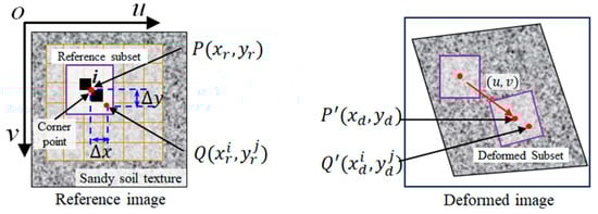
Figure 6.
Schematic principle of correlation matching algorithm.
3. Results
3.1. Experimental Setup
The testing system consists of a flume, an earth-fill dam scale, and an image acquisition device, as shown in Figure 7. The length, width, and height of the flume were 200 cm, 50 cm, and 80 cm, respectively. Three sides of the flume are made of plexiglass to facilitate observation of the water level and dam failure. The model dam was built using layered filling technology with clay and sand as materials. Its length, width and height are 50 cm, 70 cm and 20 cm, respectively. In addition, several markers were placed at equal intervals on the dam crest to measure the horizontal displacement of the dam under hydrostatic pressure. The image acquisition device primarily includes a CMOS camera and a laptop. The camera resolution is set to 2448 × 2048 pixels, and it is equipped with a 25 mm fixed focal length lens. Due to the lack of unique texture features on the surface of earth-fill dams, this study uses the cross markers arranged on the dam crest as measuring points.
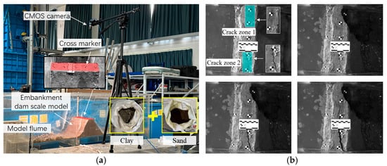
Figure 7.
Experimental setup and captured images of earth-fill dams: (a) Experimental setup; (b) Captured images.
After the experimental system is set up, water is introduced into the flume at a flow rate of 0.4 m3/s. During the water injection process, due to the ultra-fine pores, water progressively infiltrated the earth-fill dam, reducing the friction between earth particles within the dam. Due to the self-superposition and the hydrostatic water pressure, cracks will gradually appear in the dam body. The camera synchronously captures images until the dam collapses, resulting in approximately 250 images being collected.
Experiments show that as the water level rises, two primary crack zones gradually form within the dam, as shown in Figure 7b. Crack Zone 1 appeared first near the crest, where three initial microcracks gradually widened and merged into a continuous major crack under increasing pore-water pressure and tensile stress concentration. This stage was followed by local instability and partial collapse of the downstream face. The subsequent structural degradation reduced the dam’s overall load-bearing capacity, promoting the initiation of Crack Zone 2, which propagated toward the collapse area of Crack Zone 1 until the two zones became fully connected. After the upstream portion of Crack Zone 1 collapsed, a breach formed through the dam, triggering a hydraulic jump at the downstream side.
Dataset Preparation and Annotation Approximately 250 images were collected during the experiment. To meet model input requirements and enhance training efficiency, all images were cropped and uniformly scaled to 640 × 640 pixels. The dataset covers the entire lifecycle of cracks, from initiation and propagation to failure, and includes diverse surface textures under various moisture and lighting conditions, creating challenging scenarios for robustness testing. The dataset was strictly partitioned into training (approx. 200 images), validation (approx. 25 images), and test sets (approx. 25 images) following an 8:1:1 ratio. The model was trained entirely using Supervised Learning. We used the professional annotation tool LabelMe to perform precise, pixel-level manual annotation of cracks in every image. The annotations were cross-checked by two researchers to ensure high quality.
Model Training Strategy All models were trained on an NVIDIA Tesla V100 GPU with 32GB of memory. To enhance performance, we employed a Transfer Learning strategy by initializing our network with weights from a YOLOv8 model pre-trained on the large-scale MS COCO dataset, followed by fine-tuning on our crack dataset. To prevent overfitting and improve generalization, extensive online Data Augmentation was applied, including geometric transformations (random rotations, flips, scaling) and photometric distortions (random brightness and contrast adjustments). The SGD optimizer was used with an initial learning rate of 0.01, adjusted via a cosine annealing schedule. Models were trained for 300 epochs with a batch size of 8.
3.2. Experimental Results of Crack Segmentation
- (1)
- Performance comparison of models
YOLOv8m was selected as the baseline model for improvement. This choice was based on YOLOv8m’s favorable balance between computational efficiency and detection accuracy. This balance meets the requirements of structural health monitoring applications for both real-time processing and high precision. To assess performance, this study compared four instance segmentation models: YOLOv5m, YOLOv7, the baseline YOLOv8m, and our proposed YOLOv8-CGA method. For clarity in direct comparison against the baseline, this proposed method will be referred to as the ‘YOLOv8-CGA’ throughout this results section. Evaluation metrics included precision, recall, and mAP50 for both bounding box and segmentation mask predictions.
Detailed experimental results are shown in Table 1. The data indicate that the YOLOv8-CGA model achieved the best performance across all key metrics. Specifically, its precision for both bounding box and mask prediction reached 1.0. The recall was 0.833. Both box mAP50 and mask mAP50 achieved the highest value of 0.917.

Table 1.
Performance comparison of 5 models for crack segmentation in earth-fill dams.
Further analysis reveals specific improvements. Compared to YOLOv5m, the YOLOv8-CGA’s box mAP50 (0.917) significantly exceeded YOLOv5m’s (0.766). Its mask mAP50 (0.917) also substantially surpassed YOLOv5m’s (0.572). When compared with YOLOv7, our model’s box mAP50 (0.917) was superior to YOLOv7’s (0.877). Furthermore, its mask mAP50 (0.917) dramatically outperformed YOLOv7’s (0.546), highlighting significant advantages in segmentation accuracy and false positive suppression. Compared to the baseline YOLOv8m, the improved model increased both box and mask mAP50 by 0.093 (from 0.824 to 0.917). While maintaining recall at 0.833, precision improved from 0.761 to 1.0. These results validate the effectiveness of our proposed improvement strategy.
Regarding model complexity, the YOLOv8-CGA contains 27.6 million parameters. This is comparable to the baseline YOLOv8m (27.2M), significantly lower than YOLOv7 (36.9M), and slightly higher than YOLOv5m (21.2M). This outcome demonstrates that the proposed strategy enhances performance while maintaining high model efficiency. It offers an optimized solution that balances accuracy and efficiency for instance segmentation tasks.
- (2)
- Crack detection visualization of models
Figure 8 shows a visual comparison of results from different deep learning algorithms on the dam crack detection task. Analyzing the first column image sample: the YOLOv5m model failed to identify the lower vertical crack. It also misidentified the scale bar as a crack. YOLOv7 detected the vertical crack but produced considerable false positives. YOLOv8m also failed to recognize the lower vertical crack and generated a substantial false detection in the lower part of the image.
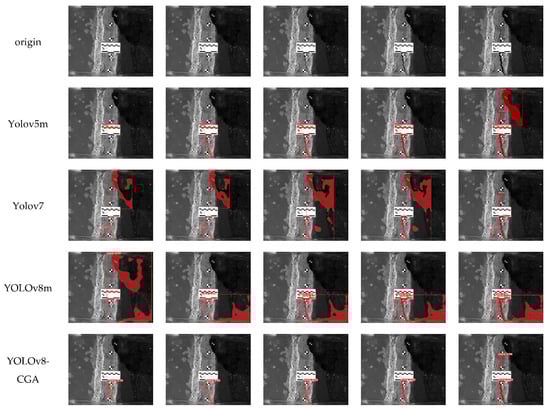
Figure 8.
Visual comparison of 5 segmentation methods in the dam crack scene.
In the second through fourth column images: YOLOv5m, YOLOv7, and YOLOv8m all showed varying levels of false detections, indicating fundamental limitations in distinguishing cracks from complex dam surface textures. In contrast, the YOLOv8-CGA model precisely identified the existing vertical cracks, exhibiting higher detection precision.
The fifth column presents a complex scenario with multiple co-existing cracks. In this scene, YOLOv5m misinterpreted shadow regions as cracks. YOLOv7 misjudged surface protrusions as cracks. YOLOv8m incorrectly labeled a larger shadow area as a crack. Conversely, the YOLOv8-CGA accurately detected the two actual cracks without any false positives. This demonstrates its superior segmentation accuracy.
In summary, comparative visual analysis confirms the enhanced performance of the YOLOv8-CGA model for the earth-fill dams crack detection. The model shows significant advantages, especially in handling complex background textures, dealing with scenes containing multiple co-existing cracks, and suppressing false detections. It can provide more reliable technical support for dam SHM.
3.3. Experimental Results of Crack Width
Following crack segmentation, edge detection, and skeleton extraction within the identified red rectangular area shown in Figure 8, crack widths were calculated using the method introduced in Section 2.1.2. The processed result of one image is depicted in Figure 9. The blue lines along the skeleton’s normal direction in Figure 9d represent the widths of 100 randomly selected cross-sections. The width of each section of the entire crack is illustrated in Figure 10a. This result is largely consistent with measurements obtained using a crack meter, with a discrepancy of less than 0.1 mm.

Figure 9.
Calculation process of crack parameters: (a) recognized crack areas; (b) crack segmentation; (c) cracked edges and skeleton; (d) 100 random crack sections.
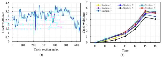
Figure 10.
Statistics and analysis of crack widths: (a) width of each section of the entire crack; (b) evolution of crack widths in the specified sections.
Crack evolution trends are crucial for assessing the health status of the structure. The crack widths at six time points for the crack section shown in Figure 9a were statistically analyzed, as presented in Figure 10b. It is evident that each section of the crack underwent stages of initiation, propagation, and stabilization, which aligns completely with the experimental results.
3.4. Experimental Results of Displacement and Strain Measurements
To further investigate the mechanisms of crack initiation, development, and prognosis in the earth-fill dam, the DIC technique was employed to compute the full-field displacement and strain in the crack region. As shown in Figure 11a, the crack zone was defined as the region of interest (ROI), and approximately 100 sequential images were analyzed.
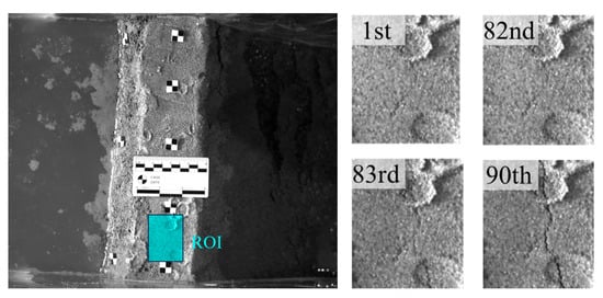
Figure 11.
Calculation of displacement and strain in the crack region: (a) region of interest; (b) crack region at different stages.
Figure 11b presents several representative images of the crack region at different testing stages. The first image corresponds to the initial state of the test and was used as the reference image for DIC computation. The 82nd image represents the last stage at which the DIC algorithm could still ensure reliable matching accuracy, and no visible crack was observed at this point. The 83rd image captures the onset of cracking, where the correlation accuracy of the DIC template begins to degrade slightly due to discontinuous localized deformation. After that, the crack gradually developed, and the geometry of the crack became progressively more distinct and well defined in the 90th image.
Figure 12 shows the displacement and maximum principal strain fields in the crack region at different testing stages. A pronounced discontinuity can be clearly observed in the displacement field of Figure 12a, becoming increasingly evident as the water level rises. The corresponding strain field, illustrated in Figure 12b, exhibits localized strain concentration zones near the crack initiation sites, particularly in the 74th and 82nd images. Notably, at these stages, no visible cracks were detected in the raw images, indicating that DIC-derived strain fields can reveal deformation precursors well before crack manifestation.
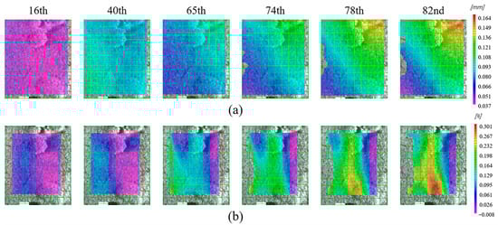
Figure 12.
Deformation in the crack region obtained using DIC: (a) displacement field; (b) maximum principal strain field.
By correlating the evolution of strain concentration with the crack propagation history, it becomes evident that regions with high strain gradients appear prior to visible crack extension. This observation suggests that the strain field serves as an effective indicator for early-stage prognosis of crack growth and potential failure. Overall, the results demonstrate that deformation gradients derived from DIC data contain rich prognostic information that can be utilized to forecast the onset, direction, and rate of crack propagation, thereby highlighting the broader potential of DIC for SHM and failure prognosis for earth-fill dams.
Crack propagation induces displacement in the dam. To measure displacements at different sections, five measurement points were selected at approximately equal intervals along the dam crest, as shown in Figure 13. The first pair of images acquired by the camera serves as the reference image, while the remaining images are considered deformed. The coordinates of the measurement points in the reference image are determined using the corner point detection algorithm described in Section 2.2, and their coordinates in the deformed images are determined by DIC subset matching. The pixel displacement of each measurement point is calculated by subtracting its pixel coordinate in the reference image from its pixel coordinate in the deformed image. This displacement is then multiplied by a scale factor to determine the x-y plane displacement of the measurement point.
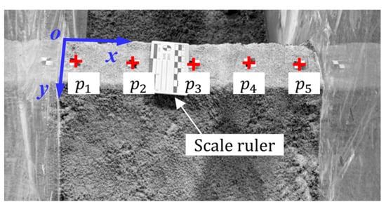
Figure 13.
Location of the measurement points in the dam.
To explicitly illustrate the displacement due to dam deformation, we analyzed only the 80 images captured before the collapse. The displacements are shown in Figure 14. It is observed that the displacement curves of points p1 and p5 differ significantly from the other three points. Notably, p1 exhibits no obvious displacement throughout the process, whereas p5 shows the largest displacement and is the first measurement point to be significantly displaced. This is attributed to the appearance of two major cracks during the experiment. The first crack appeared in the area of p5, resulting in significant displacement. As the water level rose, this area became a failure initiation zone, leading to failure. The second crack initially appeared near p2 and gradually extended towards p3 and p4, resulting in similar displacement trends for these three points of interest. In summary, the displacement curve shown in Figure 12 is consistent with the actual scenario, verifying the feasibility of DIC technology for dam displacement measurement.
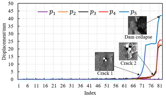
Figure 14.
Displacement curves of measurement points.
4. Discussion
This study is part of dam structural health monitoring, focusing on crack detection and deformation measurement in earth-fill dams. It investigates and validates the feasibility of computer vision technology in crack detection and deformation measurement for these dams, and overcomes the limitations of traditional methods in complex backgrounds. By improving upon previous research, the intelligence and accuracy of earth-fill dam SHM are enhanced.
The architecture of YOLOv8 is primarily optimized for bounding box detection, which remains limited in accurately delineating fine, irregular crack boundaries in the complex background of earth-fill dams, leading to suboptimal segmentation precision. A YOLOv8-CGA model is proposed by incorporating the CGA mechanism into the YOLOv8 framework. Experiments conducted to verify the effectiveness of this improved model showed that both box mAP50 and mask mAP50 achieved 0.917. This indicates that the YOLOv8-CGA model performs better than existing technologies in terms of detection accuracy and robustness for crack segmentation in earth-fill dams.
Crack width is the most important geometric parameter of cracks. High accuracy width detection enables a more accurate assessment of structural health status. Currently, the crack width calculation method based on skeleton lines is considered the preferred option [41,42]. Given the geometric discontinuity of cracks in earth-fill dams, the circumscribed circle method is employed to determine curvature. This method relies on three-point geometric relationships rather than derivative approximations, eliminating parameter dependence and achieving reliable performance, even for cracks exhibiting sharp geometric discontinuities. According to the determined curvature, the fitting strategy is adaptively selected and five adjacent points along the skeleton line in two directions with the measurement point as the center are used as fitting points to obtain the skeleton curve. This method aligns well with the geometric variability of fractures and provides a robust foundation for subsequent width calculation.
The DIC method proves particularly advantageous for earth-fill dams compared with concrete structures, since the gradual deformation and lower brittleness of soil materials allow DIC to capture the early strain localization and deformation gradients that signal impending crack initiation and failure. Displacement sensors are commonly employed in conventional dam monitoring. For some large-scale and inaccessible environments scenarios, the sensor deployment and data transmission that the technology relies on remain challenging. DIC technology has demonstrated great potential for application in dam displacement measurement due to its advantages of non-contact, long-distance, and full-field measurement. The camera was precisely aligned horizontally to avoid interference from out-of-plane displacement. Experimental validation confirms DIC not only provides accurate displacement and strain measurements but also offers a powerful means to visualize and predict deformation trends leading to structural failure.
While the proposed methods have been verified through model experiments, their performance in real structures requires further investigation due to differences in measurement environments and accuracy. Full-scale structures exhibit spatial dimensions exceeding—hundreds of meters with numerous inaccessible locations. If the fixed measuring station used in this study is applied, a higher resolution camera will need to be replaced to provide sufficient measurement accuracy. Additionally, equipping the camera with a suitable telephoto lens is advisable.
Compared to fixed measurement stations, drone-assisted image acquisition provides comprehensive coverage, high precision, and low cost. However, there are currently two critical challenges: (1) determining the conversion relationship between pixels and physical scales; (2) unifying data from different time periods into a single coordinate system. Future studies will address these challenges to develop efficient and highly accurate SHM technology for dams.
5. Conclusions
This study conducted hydraulic model experiments on earth-fill dams, proposing an innovative three-step crack detection methodology specifically designed for complex dam surface textures. Specifically, a YOLOv8-CGA crack segmentation method was developed by introducing the Cascade Group Attention mechanism into YOLOv8, and an adaptive crack skeleton fitting method was developed to improve the accuracy of crack width calculations. Additionally, the 2D displacements of the dam crest and strain field of the crack zone were measured using digital image correlation methods. To validate the effectiveness of the proposed method, it was compared with three commonly used models. The results indicate that the proposed method offers more efficient crack segmentation and accurate calculation of crack width. This study provides a novel and efficient technical approach for the SHM of dams, helping to enhance their resilience in the context of climate change. The study results also hold application value for the SHM of other outdoor engineering structures. Future work should focus on validating the method’s generalization on real-world dams and addressing its scale sensitivity to micro-cracks.
Author Contributions
Conceptualization, W.F. and S.M.; methodology, W.F.; software, W.F.; validation, S.C., W.D. and L.F.; formal analysis, W.F. and S.M.; investigation, L.F.; resources, W.D.; data curation, W.F.; writing—original draft preparation, W.F.; writing—review and editing, S.C.; visualization, S.M.; supervision, W.D.; project administration, S.M.; funding acquisition, W.F. and S.M. All authors have read and agreed to the published version of the manuscript.
Funding
This research was funded by the Nanxun Scholars Program for Young Scholars of ZJWEU, grant number RC2023021041 and A Project Supported by the Scientific Research Fund of the Zhejiang Provincial Education Department, grant number Y202147608.
Institutional Review Board Statement
Not applicable.
Informed Consent Statement
Not applicable.
Data Availability Statement
The original contributions presented in this study are included in the article material. Further inquiries can be directed to the corresponding authors.
Conflicts of Interest
The authors declare no conflicts of interest.
Correction Statement
This article has been republished with a minor correction to the Data Availability Statement. This change does not affect the scientific content of the article.
References
- Gordan, B.; Raja, M.A.; Armaghani, D.J.; Adnan, A. Review on dynamic behaviour of earth dam and embankment during an earthquake. Geotech. Geol. Eng. 2022, 40, 3–33. [Google Scholar] [CrossRef]
- Wang, F.; Tulamaiti, Y.; Fang, H.; Yu, X.; Zhou, C. Seismic response characteristics of polymer anti-seepage wall in earth dam based on earthquake wave motion input method. Structures 2023, 47, 358–373. [Google Scholar] [CrossRef]
- He, K.; Song, C.; Fell, R. Numerical modelling of transverse cracking in embankment dams. Comput. Geotech. 2021, 132, 104028. [Google Scholar] [CrossRef]
- Xiong, J.; Lu, W.; Wang, G.; Chen, M.; Wang, Y.; Liu, J. Vertical crack identification of arch dam under underwater explosion based on mode transition. Structures 2024, 59, 105671. [Google Scholar] [CrossRef]
- Park, G.; Cudney, H.H.; Inman, D.J. Impedance-based health monitoring of civil structural components. J. Infrastruct. Syst. 2000, 6, 153–160. [Google Scholar] [CrossRef]
- Hu, H.; Li, Z.; He, Z.; Wang, L.; Cao, S.; Du, W. Road surface crack detection method based on improved YOLOv5 and vehicle-mounted images. Measurement 2024, 229, 114443. [Google Scholar] [CrossRef]
- Stałowska, P.; Suchocki, C.; Rutkowska, M. Crack detection in building walls based on geometric and radiometric point cloud information. Autom. Constr. 2022, 134, 104065. [Google Scholar] [CrossRef]
- Steen, C.V.; Pahlavan, L.; Verstrynge, E. Smart aggregates for acoustic emission monitoring of concrete cracking and reinforcement corrosion. Constr. Build. Mater. 2024, 443, 137644. [Google Scholar] [CrossRef]
- Deng, Z.; Gao, Q.; Huang, M.; Wan, N.; Zhang, J.; He, Z. From data processing to behavior monitoring: A comprehensive overview of dam health monitoring technology. Structures 2025, 71, 108094. [Google Scholar] [CrossRef]
- Kheradmandi, N.; Mehranfar, V. A critical review and comparative study on image segmentation-based techniques for pavement crack detection. Constr. Build. Mater. 2022, 321, 126162. [Google Scholar] [CrossRef]
- Cheng, H.D.; Chen, J.R.; Glazier, C. Novel approach to pavement cracking detection based on fuzzy set theory. J. Comput. Civ. Eng. 1999, 13, 270–280. [Google Scholar] [CrossRef]
- Kirschke, K.R.; Velinsky, S.A. Histogram-based approach for automated pavement-crack sensing. J. Transp. Eng. 1992, 118, 700–710. [Google Scholar] [CrossRef]
- Golding, V.P.; Gharineiat, Z.; Munawar, H.S.; Ullah, F. Crack detection in concrete structures using deep learning. Sustainability 2022, 14, 8117. [Google Scholar] [CrossRef]
- Laxman, K.; Tabassum, N.; Ai, L.; Cole, C.; Ziehl, P. Automated crack detection and crack depth prediction for reinforced concrete structures using deep learning. Constr. Build. Mater. 2023, 370, 130709. [Google Scholar] [CrossRef]
- Fan, C.L. Evaluation model for crack detection with deep learning: Improved confusion matrix based on linear features. J. Constr. Eng. Manag. 2025, 151, 04024210. [Google Scholar] [CrossRef]
- Liu, Y.; Yao, J.; Lu, X.; Xie, R.; Li, L. DeepCrack: A deep hierarchical feature learning architecture for crack segmentation. Neurocomputing 2019, 338, 139–153. [Google Scholar] [CrossRef]
- Han, C.; Ma, T.; Huyan, J.; Huang, X.; Zhang, Y. CrackW-Net: A novel pavement crack image segmentation convolutional neural network. IEEE Trans. Intell. Transp. Syst. 2021, 23, 22135–22144. [Google Scholar] [CrossRef]
- Al-Huda, Z.; Peng, B.; Algburi, R.N.A.; Al-antari, M.A.; Al-Jarazi, R.; Zhai, D. A hybrid deep learning pavement crack semantic segmentation. Eng. Appl. Artif. Intell. 2023, 122, 106142. [Google Scholar] [CrossRef]
- Lu, X.; Li, Q.; Li, J.; Zhang, L. Deep learning-based method for detection and feature quantification of microscopic cracks on the surface of concrete dams. Measurement 2025, 240, 115587. [Google Scholar] [CrossRef]
- Zhou, J.; Zhao, G.; Li, Y. Vison Transformer-Based Automatic Crack Detection on Dam Surface. Water 2024, 16, 1348. [Google Scholar] [CrossRef]
- Huang, B.; Kang, F.; Li, X.; Zhu, S. Underwater dam crack image generation based on unsupervised image-to-image translation. Autom. Constr. 2024, 163, 105430. [Google Scholar] [CrossRef]
- Guo, B.; Li, X.; Li, D. Crackwave R-convolutional neural network: A discrete wavelet transform and deep learning fusion model for underwater dam crack detection. Struct. Health Monit. 2025. [Google Scholar] [CrossRef]
- Zhu, Y.; Niu, X.; Tian, J. A machine vision-based intelligent segmentation method for dam underwater cracks using swarm optimization algorithm and deep learning. Comput. Aided Civ. Infrastruct. Eng. 2025, 40, 1405–1417. [Google Scholar] [CrossRef]
- Li, Y.; Zhao, H.; Wei, Y.; Bao, T.; Li, T.; Wang, Q. Vision-guided crack identification and size quantification framework for dam underwater concrete structures. Struct. Health Monit. 2025, 24, 2125–2148. [Google Scholar] [CrossRef]
- Khan, U.S.; Ishfaque, M.; Khan, S.U.R.; Xu, F.; Chen, L.; Lei, Y. Comparative analysis of twelve transfer learning models for the prediction and crack detection in concrete dams, based on borehole images. Front. Struct. Civ. Eng. 2024, 18, 1507–1523. [Google Scholar] [CrossRef]
- Dai, Q.; Ishfaque, M.; Khan, S.U.R.; Luo, Y.L.; Lei, Y.; Zhang, B. Image classification for sub-surface crack identification in concrete dam based on borehole CCTV images using deep dense hybrid model. Stoch. Environ. Res. Risk Assess. 2024, 39, 4367–4654. [Google Scholar] [CrossRef]
- Pal, M.; Palevičius, P.; Landauskas, M.; Orinaitė, U.; Timofejeva, I.; Ragulskis, M. An overview of challenges associated with automatic detection of concrete cracks in the presence of shadows. Appl. Sci. 2021, 11, 11396. [Google Scholar] [CrossRef]
- Panella, F.; Lipani, A.; Boehm, J. Semantic segmentation of cracks: Data challenges and architecture. Autom. Constr. 2022, 135, 104110. [Google Scholar] [CrossRef]
- Redmon, J.; Farhadi, A. Yolov3: An incremental improvement. arXiv 2018, arXiv:1804.02767. [Google Scholar] [CrossRef]
- Sohan, M.; Sai Ram, T.; Rami Reddy, C.V. A review on yolov8 and its advancements. In Proceedings of the International Conference on Data Intelligence and Cognitive Informatics, Tirunelveli, India, 27–28 June 2024; pp. 529–545. [Google Scholar]
- Liu, X.; Peng, H.; Zheng, N.; Yang, Y.; Hu, H.; Yuan, Y. Efficientvit: Memory efficient vision transformer with cascaded group attention. In Proceedings of the IEEE/CVF Conference on Computer Vision and Pattern Recognition, Vancouver, BC, Canada, 17–24 June 2023; pp. 14420–14430. [Google Scholar]
- Yu, C.; Shin, Y. MCG-RTDETR: Multi-convolution and context-guided network with cascaded group attention for object detection in unmanned aerial vehicle imagery. Remote Sens. 2024, 16, 3169. [Google Scholar] [CrossRef]
- Tomasi, C.; Manduchi, R. Bilateral filtering for gray and color images. In Proceedings of the Sixth International Conference on Computer Vision, Bombay, India, 4–7 January 1998; pp. 839–846. [Google Scholar]
- Otsu, N. A threshold selection method from gray-level histograms. Automatica 1975, 11, 23–27. [Google Scholar] [CrossRef]
- Cornea, N.D.; Silver, D.; Min, P. Curve-skeleton properties, applications, and algorithms. IEEE Trans. Vis. Comput. Graph. 2024, 13, 530–548. [Google Scholar] [CrossRef]
- Canny, J. A computational approach to edge detection. IEEE Trans. Pattern Anal. Mach. Intell. 2009, PAMI-8, 679–698. [Google Scholar] [CrossRef]
- Chu, T.C.; Ranson, W.F.; Sutton, M.A. Applications of digital-image-correlation techniques to experimental mechanics. Exp. Mech. 1985, 25, 232–244. [Google Scholar] [CrossRef]
- Bruck, H.A.; McNeill, S.R.; Sutton, M.A. Digital image correlation using Newton-Raphson method of partial differential correction. Exp. Mech. 1989, 29, 261–267. [Google Scholar] [CrossRef]
- Pan, B.; Xie, H.; Wang, Z. Equivalence of digital image correlation criteria for pattern matching. Appl. Opt. 2010, 49, 5501–5509. [Google Scholar] [CrossRef] [PubMed]
- Harris, C.; Stephens, M. A combined corner and edge detector. In Proceedings of the Alvey Vision Conference, Manchester, UK, 31 August–2 September 1988. 10-5244. [Google Scholar]
- Li, Z.; Miao, Y.; Torbaghan, M.E.; Zhang, H.; Zhang, J. Semi-automatic crack width measurement using an OrthoBoundary algorithm. Autom. Constr. 2024, 158, 105251. [Google Scholar] [CrossRef]
- Huang, H.; Wu, Z.; Shen, H. A three-stage detection algorithm for automatic crack-width identification of fine concrete cracks. J. Civ. Struct. Health Monit. 2024, 14, 1373–1382. [Google Scholar] [CrossRef]
Disclaimer/Publisher’s Note: The statements, opinions and data contained in all publications are solely those of the individual author(s) and contributor(s) and not of MDPI and/or the editor(s). MDPI and/or the editor(s) disclaim responsibility for any injury to people or property resulting from any ideas, methods, instructions or products referred to in the content. |
© 2025 by the authors. Licensee MDPI, Basel, Switzerland. This article is an open access article distributed under the terms and conditions of the Creative Commons Attribution (CC BY) license (https://creativecommons.org/licenses/by/4.0/).