Abstract
Offshore wind turbines (OWTs) with higher capacity are typically associated with larger structural dimensions, such as increased hub height, tower diameter, and rotor diameter. Consequently, they require support structures with large-diameter piles, particularly when employing suction buckets, a type of large-diameter foundation. These large-diameter structures exhibit a distinct scour mechanism compared to the conventional mechanisms observed in smaller-diameter piles. This study investigates the scour risk of OWTs while explicitly accounting for the large pile effect. First, a scour fragility analysis is developed to evaluate the vulnerability of suction bucket foundations under scour, represented in terms of fragility curves. Then, the probability density function (PDF) of scour depth is derived from the PDF of the Keulegan–Carpenter number, a key parameter for estimating scour depth that incorporates the large pile effect. Ultimately, scour risk is quantified by integrating the PDF of scour depth with the corresponding scour fragility curve. Comparative results show that, with a safety factor of 1.0, the reliability indices considering the large-diameter pile effect are 2.509, significantly lower than 5.115 for cases that neglect this effect, representing a decrease of less than 51%. For a safety factor of 1.75, the difference is 43%. These results suggest that ignoring the large-diameter pile effect not only underestimates the scour risk of OWTs, but also demonstrates a nonlinear effect of the safety factor on OWT risk. Ignoring this effect could also compromise the sustainability of offshore wind turbine systems. This highlights the importance of considering the unique scour mechanisms associated with large-diameter OWT foundations to avoid overestimating structural risk.
1. Introduction
Scour is a phenomenon that occurs when a structure is installed and the flow of fluid changes, and it is sensitive to the decrease in the bearing capacity of the structure. Numerous studies have been conducted to demonstrate the negative effects of scour on the dynamic response of OWT structures. For example, Prendergast et al. [1] conducted a numerical study to examine the effect of scour on the natural frequency of an OWT and concluded that scour significantly reduces the oscillation frequency of the OWT but to different extents depending on the soil stiffness profiles. Li et al. [2] used a model experiment on wind turbine monopiles and found that the moment capacity of the pile foundation decreased almost linearly with the depth of scour. Also using a series of experiments in geotechnical centrifuges. Chortis et al. [3] investigated the influence of scour on the lateral response of a monopile foundation. Zhang et al. [4] adjusted the soil profile parameters to accurately consider the scour-hole dimensions to examine their influence on the impedance of monopiles. Jiang et al. [5] proposed a simple method to evaluate the seismic response of an OWT under post-scour conditions. The results recommended that the shape of the scour hole should be simulated with an ideal slope angle of 30°. Qin et al. [6] divided an experiment into two phases to observe the mutual influences of the scour formation around the pile foundation on the foundation displacement, water flow, and interruption in OWT operation. Wang et al. [7] examined how solidified soil influences the lateral bearing capacity of monopiles subjected to different scour conditions and evaluated the performance of various scour mitigation techniques.
With the increasing demand for higher-capacity OWTs to meet global renewable energy targets, the structural dimensions of these turbines, including hub height, tower diameter, and rotor diameter, have significantly increased [8]. This trend necessitates the use of large-diameter foundation systems, such as suction buckets or large monopiles, to ensure structural stability under harsh marine environments. However, these large-diameter foundations introduce distinct scour mechanisms that differ from those observed in conventional smaller-diameter piles. Unlike smaller piles, where scour is primarily driven by localized flow patterns, large-diameter piles alter the surrounding hydrodynamic conditions, leading to more complex scour patterns and potentially deeper scour holes. These unique mechanisms can significantly amplify the scour risk, thereby affecting the long-term stability and reliability of OWT foundations. The dynamic behavior of this type of suction bucket foundation has been thoroughly studied by centrifuge model tests [9,10,11], scaled model tests [12,13], and numerical simulations [14,15,16,17,18]. The study of the influence of scour on the suction bucket foundation has also attracted much attention. Ngo et al. [19] compared the scour fragility curve of the suction bucket foundation under different loading combinations. Cheng et al. [20] conducted a numerical study to investigate the influence of scour on the ultimate bearing capacity of the suction bucket foundation in clay soil.
Despite the growing body of research on scour effects, many existing studies apply scour mechanisms to small-diameter piles. They may not sufficiently account for the unique scour behavior associated with large-diameter foundations. This oversight can lead to an overestimation or underestimation of scour risk, potentially compromising the safety and performance of OWTs. To address this gap, this study investigates the scour risk of OWTs with a specific focus on the large-diameter foundation effect. Previous studies have used deterministic methods to determine the maximum scour depth (e.g., maximum scour depth) when considering the effects of large diameter piles. However, this method can underestimate or overestimate actual phenomena, and probabilistic methods have been introduced to compensate for this. Kim et al. proposed and studied a probabilistic method for scour, but their study also focused on small piles and did not consider the effects of large diameter piles. By developing a scour fragility analysis and deriving the probability density function (PDF) of scour depth based on the Keulegan–Carpenter (KC) number, this research quantifies the scour risk through fragility curves adapted to large-diameter suction bucket foundations. The findings aim to provide a more accurate assessment of structural vulnerabilities and highlight the importance of incorporating large pile effects in the design and risk evaluation of OWT foundations. This study contributes to improving the reliability and safety of next-generation OWTs, supporting the sustainable development of offshore wind energy.
2. Fragility Analysis Development
Fragility analysis is a well-established method in seismic engineering to assess the vulnerability of structures by quantifying the probability of exceeding specific damage states under varying levels of seismic intensity, typically measured by peak ground acceleration (PGA). In this study, this approach is adapted to evaluate the vulnerability of OWT foundations, specifically suction bucket foundations, under scour conditions. The scour depth (SD), ranging from 0 to 6.5, is adopted as the intensity measure, analogous to PGA, to represent the extent of soil erosion around the foundation.
The development of scour fragility curves involves a systematic algorithm to compute the probability of the suction bucket foundation exceeding predefined damage states, defined in terms of bearing capacity reduction, as a function of SD. The algorithm is structured as follows:
- 1.
- Define Damage States: Define the damage state for the suction bucket foundation as the condition where the reaction force (RF) under combined wind and wave loading under specific SD exceeds its bearing capacity (BC). If RF > BC, the foundation is considered to have failed.
- 2.
- Select Scour Depth Range: Discretize the scour depth (SD) into increments from 0 to 6.5 to cover a range of scour conditions, from no scour to severe scour scenarios.
- 3.
- Model Structural Response: Use numerical simulations to model the structural response of the suction bucket foundation under each SD, subjected to various combinations of wind and wave loading. For each SD, multiple simulations are performed with different load combinations, and the reaction force (RF) at the foundation base is calculated using finite element analysis. The corresponding BC is determined based on the reduced soil support due to scour. For each simulation, an indicator is assigned: if RF exceeds the BC, and if no damage is observed (RF less than the BC).
- 4.
- Calculate Conditional Probabilities: For each damage state DS, the probability of exceedance given an SD is calculated using a log-normal cumulative distribution function:
To estimate and , the maximum likelihood estimation (MLE) method is applied. Let , ,…, be the SD values from numerical simulations, and , , …, be the corresponding indicators. The likelihood function, based on the log-normal assumption, is:
n is the total number of numerical simulations to compute the maximum likelihood function. The log-likelihood function is maximized to find and :
This MLE approach ensures that and are derived from the simulation data, providing a robust fit for the fragility curve based on the failure condition (RF > BC) under varying SD and load combinations.
The scour risk evaluation method used in the present study is shown in the flowchart in Figure 1, and the large-diameter pile effect that was applied is set out in the red boxed area.
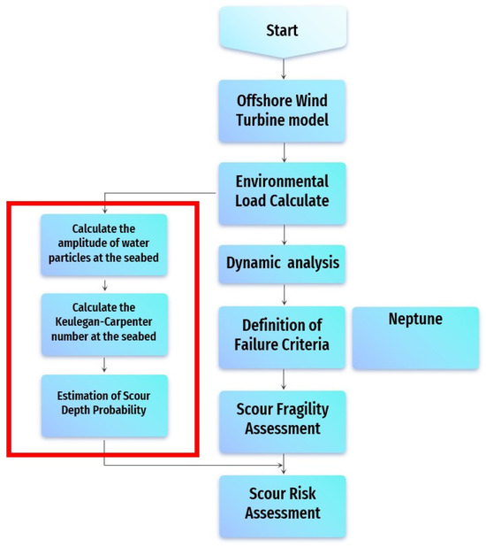
Figure 1.
Flowchart of scour risk assessment.
3. PDF of SD
The probability density function (PDF) of SD is essential for assessing the vulnerability of OWT foundations, particularly suction bucket foundations, under varying scour conditions. In this study, the PDF of SD is derived based on the PDF of the Keulegan–Carpenter number (KC), following Sumer’s [21] research, with adjustments for combined waves and current and the large-diameter pile effect.
Sumer et al. [21] proposed the following empirical equation for scour depth under combined waves and current:
where D is the foundation diameter, with as the maximum orbital velocity and as the wave period. is defined by linear waves theory and is computed by . This equation is applicable only when , as wave-induced scour becomes significant above this threshold. For , the wave component becomes negligible, and the equation does not provide meaningful scour depth values.
However, when the large-diameter pile effect is considered, defined by a diameter-to-wavelength ratio D/L between 0.15 and 0.27 (where L is the wavelength), the calculated values often fall below 6. These values are typically excluded in standard applications of Equation (4), as they do not induce significant wave-induced scour. Nevertheless, for large-diameter suction bucket foundations, these lower values are relevant due to enhanced scour mechanisms. To address this, an empirical regression equation for was developed based on Sumer’s experimental data.
Sumer and Fredsøe [21] proposed scour equations for small and large diameter piles through experiments. However, they did not separately propose data and empirical equations for large diameter piles. In this study, a dataset was secured by extracting data from a graph to estimate the empirical equation for large diameter piles proposed by Sumer and Fredsøe. First, a data extraction program was used to plot points on a graph and read the corresponding data values. Table 1 presents the data set read from the experimental results graph of Sumer and Fredsøe [21]. The scour equation for large-diameter piles was then calculated through regression analysis.

Table 1.
Result of dataset.
Using the extracted data set, we estimated the empirical scour equation for large-diameter piles. The value of the data set and regression equation was 0.764. The data extracted from the graph and the results of regression analysis are shown in Figure 2.
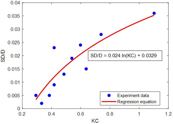
Figure 2.
Derivation of the relationship between KC and SD.
This equation allows the calculation of SD for KC values below 6, reflecting the scour behavior under large-diameter pile conditions.
The PDF of KC is computed by incorporating the large-diameter pile effect, adjusting for the range D/L from 0.15 to 0.27, where flow distortion and soil-structure interactions modify the standard KC distribution. The corresponding PDF of SD is then derived by transforming the adjusted KC PDF using the appropriate equation (Equation (4) for and the new Equation (5) for ). This approach ensures a comprehensive representation of scour depth variability, accounting for the unique hydrodynamic and geotechnical effects of large-diameter piles compared to conventional smaller-diameter piles.
4. Numerical Example
4.1. Reference Model of OWT
The reference model for this study is based on a pentapod suction bucket (SB) foundation supporting a 5.5 MW OWT, adapted for shallow seabed environments, drawing inspiration from the design outlined by Ngo et al. [19]. Unlike the approach in Ngo et al., this study employs GH Bladed software (version 3.85) for the simulation and analysis of the OWT structure.
The turbine tower, constructed from tubular steel, reaches a hub height of approximately 110 m above mean sea level (M.S.L.). It is composed of four segments, with the base diameter measuring 6 m and tapering to 5 m at the top, and the steel thickness varies along the height to balance strength and weight. The tower and SB were made of steel, and the material properties are shown in Table 2. Additional masses from the deck platform, boat landing, stairs, flanges, and other attachments are incorporated as concentrated loads along the tower, with their positions relative to M.S.L. and weights listed in Table 3. Considering the local characteristics, the support structure used a pentapod structure, and a suction bucket was used to shorten the construction period and ensure construction economy. The suction bucket has a diameter and height of 9 m and 7 m, respectively, and a thickness of 0.025 m. Figure 3 illustrates the SB substructure.
Table 2.
Steel properties.
Table 3.
Support structure node information.
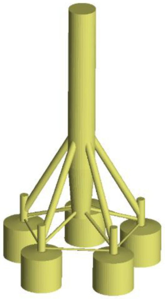
Figure 3.
Illustration of SB substructure in GH Bladed.
4.2. Soil-Structure-Interaction Simulation
There are two ways to consider the influence of the soil: directly modeling the soil in 3D and modeling it as a spring. Among these, spring modeling methods include using the P-Y curve and inputting the soil as a representative stiffness matrix. Directly modeling the soil in 3D significantly increases the physical analysis time, which can lead to problems such as increased analysis time when performing numerous analyses, as in this study. Therefore, this study calculated and applied a representative stiffness matrix for the soil.
To calculate the representative stiffness matrix, the model shown in Figure 4 was used. To calculate the stiffness matrix for six degrees of freedom, the coupling matrix relationship was established as shown in Equation (6).
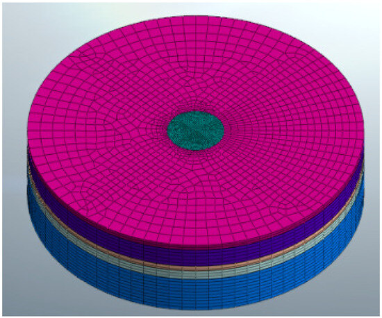
Figure 4.
Stiffness matrix analysis model.
Here, is the displacement vector, defined as and is the load vector, defined as . is a compliance matrix calculated based on the relationship between load and displacement. Finally, the soil stiffness matrix is defined by Equation (7).
The stiffness matrix is the inverse of the coupling matrix . Figure 5 shows an example of inputting the stiffness matrix calculated in the BLADED program.
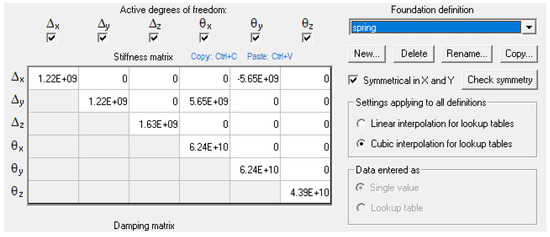
Figure 5.
Bladed input for representative stiffness matrix.
4.3. Loads on OWT
4.3.1. Wind Loads
The aerodynamic loads on offshore wind turbines are governed by the characteristics of the incoming wind field and the aerodynamic response of the rotor. In GH Bladed, the wind field is generated using a stochastic turbulence model. Accordingly, the Kaimal spectrum is employed to represent the power spectral density (PSD) of the longitudinal turbulence component:
where is the standard deviation of the wind speed fluctuation, is the integral length scale, is the mean wind speed, and is the frequency. Similar expressions are used for the lateral and vertical turbulence components with their respective parameters. Based on this spectrum, GH Bladed synthesizes a three-dimensional, time-varying turbulent wind field that acts on the rotor plane.
The aerodynamic loads are then computed using the Blade Element Momentum (BEM) method, in which each blade is divided into spanwise elements and the aerodynamic forces are obtained from local flow conditions. For a blade element at radius , the relative velocity is:
where is the incoming wind speed at hub height, is the rotor speed, and , are the axial and tangential induction factors. The elemental thrust force is expressed as:
where is air density, chord length, number of blades, and normal force coefficient derived from the airfoil characteristics. The total rotor thrust is obtained by integrating along the blade span.
4.3.2. Wave Loads
The wave force on these submerged sections is determined using the Morison equation, a widely accepted hydrodynamic model for structures in oscillatory flow:
where is the water density, is the drag coefficient, is the cylinder diameter, is the orbital velocity, is the inertia coefficient, and is the acceleration of the orbital velocity. This equation combines drag and inertia components to account for the interaction between waves and the submerged structure.
The orbital velocity and its dynamics are derived from wave characteristics, modeled using the JONSWAP spectrum, which represents realistic sea states in offshore environments. The JONSWAP spectrum is based on the general form:
where is the spectral density, is the significant wave height, is the peak period, is the wave frequency, is the peak frequency, is a scaling constant, is the peak enhancement factor, and is the spectral width parameter. This spectrum is used to generate a time-series wave elevation, from which is calculated based on linear wave theory at the relevant depth.
5. Results and Discussions
5.1. PDF of Scour Depth Results
At the study site, wave data, including significant wave height and wave period, were collected, and the KC number was calculated. For KC > 6, SD was obtained using Equation (4), while for KC < 6, Equation (5) was applied. In this study, the PDFs of SD were compared for two scenarios: considering and not considering the large-diameter pile effect. In the case without the large-diameter pile effect, only KC > 6 was used in Equation (4), consistent with conventional practice.
Figure 6 presents the PDFs of SD for suction bucket foundations under the two scenarios: (a) with the large-diameter pile effect and (b) without the large-diameter pile effect. To identify the most appropriate probability distribution, the K-S test was performed. In both cases, the log-normal distribution provided a satisfactory fit. For the case with the large-diameter pile effect, the SD follows a lognormal distribution with parameters μ = 0.760 and σ = 0.1696, resulting in a mean SD of 2.1693 m. In contrast, neglecting the large-diameter pile effect yields a lognormal distribution with μ = 0.763 and a much smaller σ = 0.0146, with a mean SD of 2.1449 m. The statistical characteristics of the two SD distributions are summarized in Table 4.
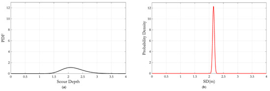
Figure 6.
Distribution of SD: (a) With large-diameter pile effect and (b) Without large-diameter pile effect.
Table 4.
The statistical characteristics of the SD distributions.
These results indicate that including the large-diameter pile effect not only slightly increases the mean scour depth but also substantially increases the variability of SD. The larger standard deviation reflects a wider spread of possible scour depths, highlighting the significant influence of the pile diameter on scour behavior. Neglecting this effect may lead to an underestimation of the uncertainty in SD, potentially resulting in non-conservative assessments of scour risk for offshore wind turbine foundations.
This study has clear limitations because it utilizes the empirical formula proposed by Sumer et al. [21]. It assumed the same soil conditions as those proposed by Sumer et al. [21], and the results could not be applied to various soil types.
5.2. Scour Fragility Curves Results
Three RFs of the suction bucket foundation were considered in the analysis to evaluate their vulnerability to scour: axial tension, axial compression, and lateral reaction. The aim was to determine whether each RF could exceed its corresponding bearing capacity (BC) under extreme scour conditions. When a reaction force remains below its BC even at a SD of 6.5 m, constructing a fragility curve for that component is not feasible, as the exceedance probability is negligible. Therefore, the OWT was first analyzed under an extreme SD of 6.5 m.
Figure 7 compares the RFs, including axial tension and axial compression, with their corresponding BCs at SD of 6.5 m under representative load cases. The seed number shown in Figure 4 indicates different realizations of the turbulent wind field used in the simulations (GH Bladed). Each seed generates a unique wind time series while preserving the same statistical properties, allowing an assessment of variability in the results. The results show that axial tension and compression RFs are significantly lower than their respective BCs across all load combinations. Consequently, the fragility curve can only be developed based on the lateral reaction force.
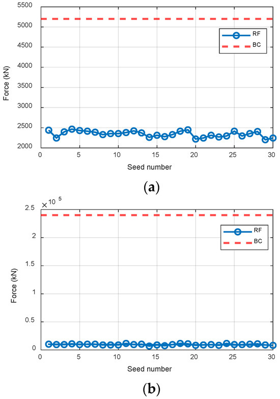
Figure 7.
Comparison of RF and BC at SD = 6.5 m in the (a) tension and (b) compression directions.
Figure 8 presents the comparison of lateral RF and its BC at SD of 4 m and seed number conditions. To calculate thrust, we created 30 wind fields by changing the seed, and calculated the wind thrust force using each wind field. Finally, the structural analysis was performed a total of 30 times, using RF at the mudline location. Using the probabilistic method described in Section 2 and incorporating safety factors, the scour fragility curves were constructed and are shown in Figure 9. The safety factor is multiplied by the member force resulting from the structural analysis to increase the applied load. It was assumed that the allowable bearing capacity at that depth does not change even if scour occurs. These curves illustrate the probability that the lateral RF exceeds its BC as a function of SD. The probability of exceedance increases with SD, remaining near zero for small depths (<1.5 m) and approaching one at larger depths, highlighting the growing vulnerability of the SB foundation. Increasing the safety factor shifts the curves toward smaller SD ranges, providing earlier warning of potential failure at lower scour depths. However, while a high safety factor ensures safety, it may also lead to inefficiency, so an appropriate value should be selected. For example, a 50% exceedance probability occurs at an SD of approximately 3.87 m for a safety factor of 1.0, whereas for a safety factor of 2.0, the 50% warning occurs already at an SD of approximately 2.43 m. The curves also confirm that the lateral reaction governs the scour-induced risk, as axial reactions remain well below their capacities. Overall, Figure 6 quantifies the influence of scour depth and safety factors on lateral force exceedance probability, providing a framework for reliability assessment and guiding maintenance planning for the suction bucket foundation.
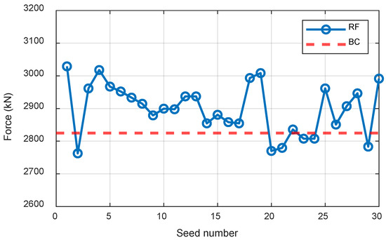
Figure 8.
Comparison of RF and BC at SD = 4 m in the horizontal directions.
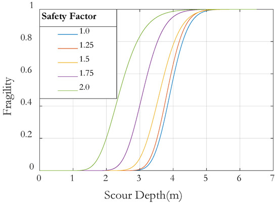
Figure 9.
Scour fragility curves considering several safety factors.
5.3. Scour Risk Results
To evaluate the scour risk () of OWTs, Equation (13) was applied, followed by Equation (14) to calculate the corresponding reliability index (. The relationship between the safety factor and the probability of failure is presented in Figure 10. It can be observed that the probability of failure increases with the safety factor, indicating that applying an excessively large safety factor may overestimate the structural risk and lead to inefficiency.
where is the scour fragility curve derived from Section 2 while represents the PDF of SD. is the SD value ranging from 0 to 6.5 m.
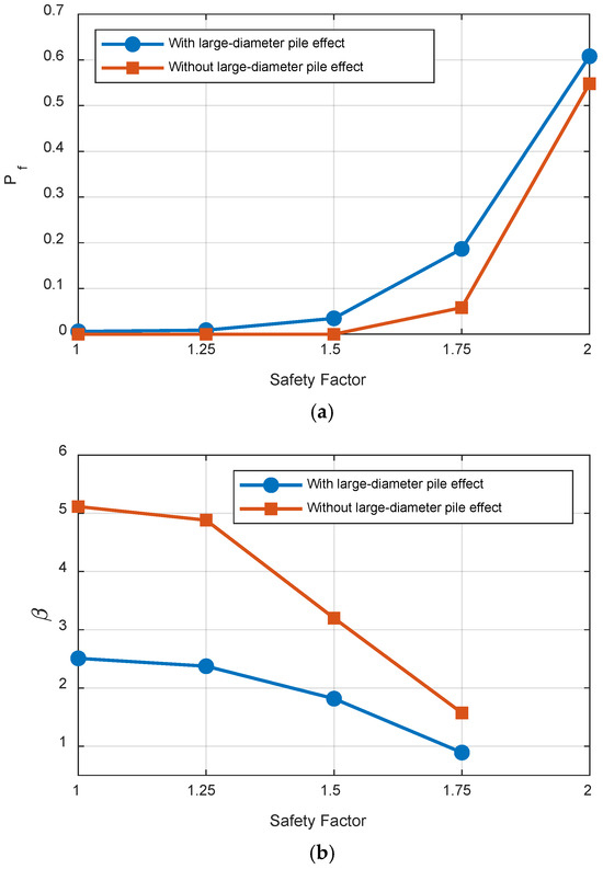
Figure 10.
(a) Scour risk (Pf) and (b) Reliability index (β) of the two cases with respect to the safety factor.
A comparative analysis of the probability of failure as well as the reliability index with respect to the safety factor was conducted for two cases: considering the large-diameter pile effect and without it. The results in Table 5 show that neglecting the large-diameter effect, i.e., ignoring the distinct erosion mechanisms in large-diameter cylindrical pile foundations, may underestimate the structural risk. For instance, at a safety factor of 1.0, neglecting the large-diameter effect yields a failure probability and safety factor of 1.57 × 10⁻⁷ and 5.1149, respectively, which are significantly different than the values of 0.006059 and 2.5086 obtained when the large-diameter effect is considered. This difference implies that the structure appears very safe under the considered loading conditions when the large-diameter effect is ignored. However, this conclusion is overly conservative and potentially misleading. In summary, this study highlights the importance of properly accounting for the erosion mechanism in OWTs with large-diameter foundations. Even though the difference in mean SD at survey location may appear small, it can lead to significant errors in structural risk assessment under scour conditions.
Table 5.
Comparison of scour risk of OWT in the case of with and without large-diameter pile effect.
When considering the effect of large-diameter piles, scour occurs when the KC is small, affecting the calculation of the mean and standard deviation of the lognormal distribution. As shown in Table 4, the log standard deviation is approximately eight times larger when considering the effect of large-diameter piles. This indicates that the area multiplied by the probability of scour occurrence expands.
A wider area multiplied by the probability of scour occurrence also increases the probability of failure.
6. Conclusions
This study proposes a framework for risk assessment of OWT suction bucket (SB) foundations. In addition, a regression equation has been established based on experimental data from previous studies to more accurately estimate the PDF of SD. The framework allows for a comprehensive consideration of the distinct scour mechanisms associated with large-diameter foundations, enabling a more precise evaluation of SD distribution and, consequently, the structural risk of OWT foundations. However, this study has clear limitations. It assumed the same soil conditions as those proposed by Sumer et al., and the results could not be applied to various soil types. Nevertheless, the main findings of this study can be summarized as follows:
- The SD distribution follows a lognormal distribution in both cases, i.e., with and without the large-diameter pile effect. The mean scour depth value are approximately 2.1693 m and 2.1446 m, respectively, representing a very small difference of about 1.2%. However, there is a substantial difference in the standard deviation of the SD distribution between the two cases.
- Vertical reactions (compression and tension) are relatively insensitive to SD and remain well below their corresponding BC, whereas horizontal reactions increase with SD.
- Although accounting for the large-diameter pile effect changes the mean scour depth values by only 1.2%, neglecting this effect can lead to an underestimation of the failure probability and the reliability index by a considerable margin, depending on the safety factor considered. For example, at a safety factor of 1.75, the underestimation reaches 43%.
- The purpose of this study was to propose a probabilistic method and to apply the previously proposed probabilistic evaluation method of scour to large-diameter piles.
This study proposes a framework for risk assessment of OWT suction bucket (SB) foundations. In addition, a regression equation has been established based on experimental data from previous studies to more accurately estimate the PDF of SD. The framework allows for a comprehensive.
When considering the large-diameter pile effect in this way, the probability of failure and reliability index change, but the existing design standards (DNV, etc.) do not recommend reviewing the large-diameter pile effect. However, to ensure the sustainability of offshore wind turbines, it is reasonable to consider the large-diameter pile effect to ensure safety.
Author Contributions
Conceptualization, D.-V.N. and Y.-J.K.; methodology, D.-H.K., D.-V.N. and Y.-J.K.; software, Y.-J.K.; validation, D.-H.K. and D.-V.N.; formal analysis, D.-V.N. and Y.-J.K.; investigation, Y.-J.K. and Y.-S.C.; resources, Y.-J.K. and Y.-S.C.; data curation, Y.-J.K. and Y.-S.C.; writing—original draft preparation, D.-H.K. and D.-V.N.; writing—review and editing, D.-H.K. and D.-V.N.; visualization, Y.-J.K.; supervision, D.-H.K. All authors have read and agreed to the published version of the manuscript.
Funding
This research was supported by the Korea Institute of Energy Technology Evaluation and Planning (KETEP) with funding from the Korean government (MOTIE)(No. 20224000000040 and No. 20224000000220, Jeonbuk Regional Energy Cluster Training of human resources).
Institutional Review Board Statement
Not applicable.
Informed Consent Statement
Not applicable.
Data Availability Statement
The original contributions presented in this study are included in the article. Further inquiries can be directed to the corresponding author.
Conflicts of Interest
The authors declare no conflicts of interest.
References
- Prendergast, L.J.; Gavin, K.; Doherty, P. An investigation into the effect of scour on the natural frequency of an offshore wind turbine. Ocean Eng. 2015, 101, 1–11. [Google Scholar] [CrossRef]
- Li, Q.; Askarinejad, A.; Gavin, K. Impact of scour on lateral resistance of wind turbine monopiles: An experimental study. Can. Geotech. J. 2020, 58, 1770–1782. [Google Scholar] [CrossRef]
- Chortis, G.; Askarinejad, A.; Prendergast, L.J.; Li, Q.; Gavin, K. Influence of scour depth and type on p–y curves for monopiles in sand under monotonic lateral loading in a geotechnical centrifuge. Ocean Eng. 2020, 197, 106838. [Google Scholar] [CrossRef]
- Zhang, H.; Liang, F.; Zheng, H. Dynamic impedance of monopiles for offshore wind turbines considering scour-hole dimensions. Appl. Ocean Res. 2021, 107, 102493. [Google Scholar] [CrossRef]
- Jiang, W.; Lin, C.; Sun, M. Seismic responses of monopile-supported offshore wind turbines in soft clays under scoured conditions. Soil Dyn. Earthq. Eng. 2021, 142, 106549. [Google Scholar] [CrossRef]
- Qin, B.; Xie, Y.; Yang, W.; Qu, R.; Geng, F. A further study on the scour around the monopile foundation of offshore wind turbines. Sustain. Energy Technol. Assess. 2023, 57, 103198. [Google Scholar] [CrossRef]
- Wang, C.; Wu, Q.; Zhang, H.; Liang, F. Effect of scour remediation by solidified soil on lateral response of monopile supporting offshore wind turbines using numerical model. Appl. Ocean Res. 2024, 150, 104143. [Google Scholar] [CrossRef]
- Global Wind Energy Council (GWEC). Global Wind Report; Global Wind Energy Council: Brussels, Belgium, 2024. [Google Scholar]
- Ueda, K.; Uzuoka, R.; Iai, S.; Okamura., T. Centrifuge model tests and effective stress analyses of offshore wind turbine systems with a suction bucket foundation subject to seismic load. Soils Found. 2020, 60, 1546–1569. [Google Scholar] [CrossRef]
- Qu, X.-Q.; Zhang, Z.-T.; Hu, J.; Wang, R.; Zhang, J.-M. Centrifuge shaking table tests on offshore wind turbine bucket foundation in mildly inclined liquefiable seabed. Soil Dynam. Earthq. Eng. 2021, 151, 107012. [Google Scholar] [CrossRef]
- Wang, X.; Yang, X.; Zeng, X. Seismic centrifuge modelling of suction bucket foundation for offshore wind turbine. Renew. Energy 2017, 114, 1013–1022. [Google Scholar] [CrossRef]
- Hung, L.C.; Lee, S.H.; Vicent, S.; Kim, S.R. An experimental investigation of the cyclic response of bucket foundations in soft clay under one-way cyclic horizontal loads. Appl. Ocean Res. 2018, 71, 59–68. [Google Scholar] [CrossRef]
- Wang, X.; Zeng, X.; Li, J. Vertical performance of suction bucket foundation for offshore wind turbines in sand. Ocean Eng. 2019, 180, 40–48. [Google Scholar] [CrossRef]
- Kourkoulis, R.S.; Gelagoti, F.M.; Lekkakis, P.C. Suction caisson foundations for offshore wind turbines subjected to wave and earthquake loading: Effect of soil-foundation interface. Geotechnique 2014, 64, 171–185. [Google Scholar] [CrossRef]
- Cheng, X.; Lu, J.; Zhuang, Q.; El Naggar, M.H.; Lu, Q.; Tu, W. Lateral cyclic behavior of OWT tripod suction bucket foundation in clays. Ocean Eng. 2022, 265, 112635. [Google Scholar] [CrossRef]
- Zhang, Y.; Zhao, S.; Zhou, H.; Andersen, K.H.; Liu, B. Long-term settlement of suction bucket foundations supporting offshore wind turbines in clay. Appl. Ocean Res. 2024, 145, 103922. [Google Scholar] [CrossRef]
- Wang, X.; Ma, C.; Li, J. Seismic response of suction bucket foundation for offshore wind turbines: A parametric study. Ocean Eng. 2022, 257, 111570. [Google Scholar] [CrossRef]
- Li, H.; Lian, J.; Liu, R.; Wang, H.; Yang, X. Research on the equivalent stiffness of bucket foundations for offshore wind power. Ocean Eng. 2024, 302, 117596. [Google Scholar] [CrossRef]
- Ngo, D.-V.; Kim, Y.-J.; Kim, D.-H. Seismic Fragility Assessment of a Novel Suction Bucket Foundation for Offshore Wind Turbine Under Scour Condition. Energies 2022, 15, 499. [Google Scholar] [CrossRef]
- Cheng, X.; Fang, Z.; Li, Q.; El Naggar, M.H.; Lu, D.; Du, X. Dynamic response of offshore wind turbine supported by suction bucket in clay considering scour. Ocean. Eng. 2024, 313, 119414. [Google Scholar] [CrossRef]
- Sumer, B.M.; Fredsøe, J. Wave scour around a large vertical circular cylinder. J. Waterw. Port Coast. Ocean Eng. 2001, 127, 125–134. [Google Scholar] [CrossRef]


Disclaimer/Publisher’s Note: The statements, opinions and data contained in all publications are solely those of the individual author(s) and contributor(s) and not of MDPI and/or the editor(s). MDPI and/or the editor(s) disclaim responsibility for any injury to people or property resulting from any ideas, methods, instructions or products referred to in the content. |
© 2025 by the authors. Licensee MDPI, Basel, Switzerland. This article is an open access article distributed under the terms and conditions of the Creative Commons Attribution (CC BY) license (https://creativecommons.org/licenses/by/4.0/).