Abstract
Ensuring reliable power system control demands innovative architectural solutions. This research introduces a fault-tolerant hybrid parallel compensator architecture for load frequency control (LFC), combining a Proportional–Integral–Derivative with Filter (PIDF) compensator with a Fuzzy Fractional-Order PI-PD (Fuzzy FOPI–FOPD) module. Particle Swarm Optimization (PSO) determines optimal PID gains, while the Catch Fish Optimization Algorithm (CFOA) tunes the Fuzzy FOPI–FOPD parameters—both minimizing the Integral Time Absolute Error (ITAE) index. The parallel compensator structure guarantees continuous operation during subsystem faults, substantially boosting grid reliability. Rigorous partial failure tests confirm uncompromised performance-controlled degradation. Benchmark comparisons against contemporary controllers reveal the proposed architecture’s superiority, quantifiable through transient metric enhancements: undershoot suppression (−9.57 × 10⁻⁵ p.u. to −1.17 × 10⁻⁷ p.u.), settling time improvement (8.8000 s to 3.1511 s), and ITAE reduction (0.0007891 to 0.0000001608), verifying precision and stability gains. Resilience analyses across parameter drift and step load scenarios, simulated in MATLAB/Simulink, demonstrate superior disturbance attenuation and operational stability. These outcomes confirm the solution’s robustness, dependability, and field readiness. Overall, this study introduces a transformative LFC strategy with high practical viability for modern power networks.
1. Introduction
1.1. General Overview
The load frequency control (LFC) system is a fundamental component in power system operation that is tasked with regulating and stabilizing the system frequency and tie-line power exchange among interconnected areas. Frequency regulation is vital for maintaining the reliability, efficiency, and overall stability of electrical power systems. As modern grids evolve with the integration of renewable energy sources, electric vehicles, and distributed generation, LFC has become a critical mechanism for maintaining real-time balance between power supply and demand across dynamic operating conditions [1]. Given its foundational importance in preserving grid integrity, it is crucial to first clarify the underlying principles governing LFC functionality—including generation load imbalance dynamics, Area Control Error (ACE) minimization objectives, and inertial response characteristics—and its critical role in sustaining nominal frequency during stochastic disturbances, abrupt load variations, and generation contingencies.
1.2. Literature Review
Despite the emergence of numerous advanced control strategies, the Proportional–Integral–Derivative (PID) controller persists as the fundamental approach within load frequency control (LFC) systems. Its control structure depends on three principal tuning parameters: proportional gain (Kp), integral gain (Ki), and derivative gain (Kd). These components operate collectively to ensure frequency stability by correcting deviations, eliminating steady-state errors, and enhancing transient performance [2]. While the classical PID controller demonstrates efficacy in frequency regulation under nominal and variable load conditions, its constrained adaptability in managing complex system dynamics and external disturbances reveals inherent operational constraints. Consequently, significant research efforts, extensively documented in the literature, have yielded a spectrum of enhanced control methodologies. These advanced approaches target augmented dynamic response, strengthened robustness against uncertainties, and improved precision in overall frequency regulation.
Modern power grids require control architectures that surpass conventional PID limitations, motivating new evolutionary directions in controller design. The Proportional–Integral–Derivative–Acceleration (PIDA) and Tilt–Integral–Derivative (TID) controllers address dynamic response constraints through specialized compensation mechanisms absent in three-parameter designs. More fundamentally, integrating fractional operators transforms the PID foundation into the five-dimensional Fractional-Order PID (FOPID) framework. This architecture uniquely enables the continuous tuning of differentiation/integration orders—providing unprecedented control over nonlinear dynamics, where discrete PID variants exhibit inherent limitations [3]. Validation studies have established that FOPID controllers consistently outperform both PIDA implementations and conventional PID across various operating regimes. However, fractional-order realization requires substantially more complex implementation than integer-based approaches, mandating comprehensive optimization of all five parameters to achieve theoretical advantages [4]. This expansion of design freedom inherently transfers complexity from modeling to computation, defining a new optimization frontier for modern control systems.
The expanded parametric dimensionality of advanced controllers, particularly FOPID’s five degrees of freedom tuning hyperspace, precipitates fundamental limitations in classical optimization paradigms. Legacy methodologies, such as Ziegler–Nichols (ZN) and Cohen–Coon, anchored in linearized approximations and empirical heuristics, prove critically insufficient for high-dimensional, nonlinear frequency regulation systems. Such approaches often result in suboptimal gain selection, persistent oscillations, or marginal stability boundaries. This impasse necessitates heuristic algorithms—including Genetic Algorithms (GA), Particle Swarm Optimization (PSO), and Simulated Annealing (SA) as essential conduits between theoretical control frameworks and physical implementation. Metaheuristic techniques exhaustively navigate the solution landscape of modern PID variants, transcending rigid classical constraints to concurrently optimize transient suppression. Achieving optimal performance in LFC necessitates a design focus on steady-state precision and computational efficiency [5]. This study presents a detailed analysis of heuristic optimization techniques, specifically examining their application in tuning PID and related controllers to enhance LFC system performance.
Prior to examining prevalent control technologies for LFC applications, advanced strategies warrant emphasis for enhancing system robustness and adaptability. Adaptive control and sliding mode control (SMC) demonstrate significant potential in this domain [6]. Adaptive control dynamically modifies controller parameters in real-time to accommodate variations in system dynamics, proving particularly effective under uncertain or fluctuating load conditions. This methodology has been successfully implemented in demanding aerospace applications where precision is critical. Nevertheless, adaptive control entails substantial design complexity and requires meticulous real-time parameter adjustment, hindering practical LFC implementation due to computational burdens [7]. Similarly, SMC is distinguished by its robustness against matched uncertainties and ability to confine system trajectories within predefined sliding manifolds, effectively neutralizing disturbances. SMC has been rigorously validated in power electronics and frequency regulation applications where reliability is paramount [8]. However, practical deployment is often limited by chattering high-frequency oscillations from discontinuous control signals. This phenomenon degrades performance and risks hardware degradation in sensitive systems. Overcoming these obstacles is crucial to fully harnessing the benefits of adaptive control and SMC for LFC, thereby promoting their broader integration into modern power systems [9]. It is widely established that the PID controller is the foremost feedback solution in industry, and it is found in over 90% of control applications [10]. In LFC systems, studies indicate that many modern control methods are fundamentally built upon the PID structure. Implementations range from basic PID controllers to advanced setups, including cascaded or gain-scheduled architectures, as well as hybrid designs that merge PID with other paradigms, such as adaptive or intelligent control. Recent progress has focused significantly on computational optimization for refining PID parameters in LFC systems. A broad spectrum of metaheuristic algorithms has emerged, including Particle Swarm Optimization (PSO) [11], Genetic Algorithm (GA) [12], Metaheuristic Anopheles Search Algorithm and Artificial Intelligence (MASAAI) [13], Artificial Bee Colony (ABC) [14], Artificial Rabbits Optimization (ARO) [15], Atom Search-Inspired Algorithm (ASIA) [16], Black Widow Optimization Algorithm (BWOA) [17], Chess Algorithm (CA) [18], Grey Wolf Optimizer (GWO) [19], lightning attachment procedure optimization (LAPO) [20], Linearized Biogeography-Based Optimization (LBBO) [21], Lyrebird Optimization Algorithm (LOA) [22], Modified Brainstorming Algorithm (MBA) [23], Marine Predator Algorithm (MPA) [24], Modified Whale Optimization Algorithm (MWOA) [25], self-adaptive bonobo optimizer (SABO) [26], and Slap Swarm Algorithm (SSA) [27].
To harness the benefits of alternative PID-based controllers in LFC applications, the authors of [28] proposed and empirically validated a PIDA controller optimized using the Competition over Resources (COR) method. This approach demonstrated superior performance compared to conventional PID controllers optimized with the same algorithms. Similarly, the authors of [29] employed multiple optimization techniques, including three optimization techniques presented in this article, to tune the controllers’ parameters. The techniques employed to optimize the parameters of PID and PIDA controllers in LFC systems include teaching–learning-based optimization (TLBO), harmony search algorithm (HS), and sine–cosine algorithm (SCA). These optimized implementations exhibited reliable and robust performance across diverse operational scenarios [30,31].
Similarly, LFC research has advanced classical PID control through novel configurations. A filtered-derivative PID (PIDF) architecture, distinguished by four independently adjustable parameters, was established by the authors of [32] for frequency regulation applications. This framework employed the Hybrid Simulated Annealing-based Quadratic Interpolation Optimizer (hSA-QIO) for parameter calibration, achieving heightened precision and operational superiority. Subsequent developments by the authors of [33] yielded a PID plus second-order derivative (PIDD2) controller through dual derivative action integration, with Ant Lion Optimizer (ALO)-tuned parameters demonstrating enhanced transient response characteristics compared to conventional PID implementations in rigorous comparative evaluations. The fractional-order PID (FOPID) controller, representing a significant evolution beyond standard PID formulations, has likewise proven effective for LFC systems. The authors of [34] validated an Aquila Optimizer (AO)-optimized FOPID implementation, achieving robust frequency stability. Further progress includes the Bees Algorithm (BA) [35], which outperformed established techniques in FOPID parameter tuning for LFC scenarios, delivering exceptional dynamic response. Complementary investigations by the authors of [36] confirmed the stabilization capabilities of a skill optimization algorithm (SOA)-enhanced FOPID controller across diverse grid operating conditions.
Additional significant advances in LFC research extend beyond conventional PID/FOPID configurations through intelligent, fuzzy-based adaptations that target enhanced dynamic regulation. A prominent example employs Grey Wolf Optimization (GWO) [37] to implement a Fuzzy-PID controller for thermal–hydro–gas multi-source load frequency control. This methodology achieves enhanced frequency/tie-line stabilization and resilience under load disturbances and generation rate constraints without returning.
Moreover, recent innovations include a fuzzy-based self-adaptive Virtual Inertia Control with Fuzzy PID secondary controller [38], optimized using the Arithmetic Optimization Algorithm (AOA). This architecture demonstrates exceptional robustness against parametric uncertainties, stochastic renewable variations, and generation–load disturbances. Further advancing this domain, ref. [39] developed an adaptive fuzzy PID controller (A-FLC-PID), optimized via hybrid moth flame optimization pattern search (h-MFO-PS). This configuration provides enhanced tuning capabilities for multi-unit hydrothermal–gas systems, significantly improving frequency regulation, disturbance rejection, and dynamic response under diverse load conditions. Complementing these advances, the authors of [40] implemented a Grey Wolf Optimizer (GWO)-optimized fuzzy self-tuned PID controller for power systems with high renewable penetration. This methodology achieves minimal frequency deviations, robust regulation, and enhanced stability compared to conventional techniques under variable load and renewable generation uncertainties.
Advancing controller design, a novel Interval Type-2 Fuzzy Logic Controller (IT2FLC) was developed [41] to enhance hybrid microgrid energy management and provide robust energy balance under renewable generation and electric vehicle integration uncertainties. Additionally, the authors of [42] proposed a hybrid Fuzzy Fractional-Order PID (FOPID) controller augmented with a PI compensator and optimized via the Catch Fish Optimization Algorithm (CFOA) for robust load frequency control in multi-area power systems, demonstrating significant performance improvements under nonlinear constraints. Complementary research presents a Quasi-Opposition Arithmetic Optimization Algorithm (QOAOA) tuned Interval Type-2 Fuzzy FOPIDN controller [43] for automatic generation control in a three-area deregulated system. This design integrates vehicle-to-grid technology and renewable sources to achieve frequency/tie-line stability with enhanced robustness under renewable fluctuations and load variations. Additionally, a fuzzy-PID-TIDμ controller optimized via the crayfish optimization algorithm (COA) was introduced in [44] for automatic generation control with redox flow batteries, ensuring precise frequency stabilization under high renewable penetration and communication delays. Collectively, these advancements substantially enhance the precision, stability, robustness, and adaptability of contemporary power grids. Table 1 systematically classifies control methodologies and associated optimization algorithms documented for LFC applications.

Table 1.
The LFC frameworks proposed in the literature.
Contemporary advancements in fuzzy control have substantially expanded methodologies for regulating nonlinear systems, with significant progress in adaptive fractional-order control. For example, the authors of [45] developed an adaptive fractional-order fuzzy PID (FO-Fuzzy-PID) controller optimized via Particle Swarm Optimization (PSO) for load frequency control in hybrid power systems. Similarly, the authors of [46] introduced a Takagi–Sugeno (T–S) fuzzy-based load frequency control (LFC) methodology incorporating switched system theory to address nonlinearities and hybrid delays in multi-area power systems, achieving enhanced robustness and superior H∞ performance. Additionally, the authors of [47] proposed a Type-3 Fuzzy Logic (T3-FL) controller for load frequency control in renewable-integrated microgrids, employing online adaptive mechanisms to enhance robustness against stochastic power fluctuations and load variations. These approaches may encounter implementation constraints in real-time LFC applications demanding millisecond response times and minimal computational overhead. Nevertheless, through targeted optimization, such strategies may demonstrate adaptability for frequency regulation. This justifies the development of a hybrid control strategy methodology presented in this work, which preserves the simplicity of Type-1 fuzzy logic while enhancing reliability through a parallel architecture specifically engineered for power system stabilization.
1.3. Motivation and Contributions
Maintaining precise frequency regulation in load frequency control (LFC) systems—especially in hybrid multi-area power networks with a high penetration of renewable energy sources—remains a critical challenge due to system nonlinearities, unpredictable load variations, and intermittent renewable energy generation. Achieving a fast, dynamic response is essential to reduce frequency deviations and enhance system stability; however, overly aggressive control may lead to overshoot or oscillations, while conservative designs risk delayed stabilization and inter-area imbalance.
Although a wide range of control approaches have been explored, including conventional PID, adaptive control, and sliding mode control, each exhibits limitations. Despite their benefits of simplicity and low cost, conventional PID controllers frequently lack sufficient robustness when faced with varying operating conditions. Intelligent methods offer adaptability but are typically complex to implement and computationally intensive. These challenges highlight the need for a hybrid solution that combines structural simplicity with intelligent adaptability.
This paper proposes an optimal two-stage control strategy for LFC applications. The first stage employs a PID controller to achieve initial stabilization. The second stage enhances performance using a fuzzy logic-based fractional-order controller (Fuzzy FOPI–FOPD), which improves disturbance rejection and nonlinear handling capabilities.
The main contributions of this study are summarized as follows:
- Innovative Controller Design: An optimal two-stage LFC configuration is proposed, integrating a PID controller with filtered derivative action (PIDF) and a fuzzy fractional-order controller (Fuzzy FOPI–FOPD). This hierarchical design enhances system stability and reliability, ensuring the control framework remains effective even in the event of partial component failure.
- Dual Optimization Framework: The first stage PIDF is optimized using Particle Swarm Optimization (PSO) for rapid convergence and simplicity. The second-stage Fuzzy FOPI–FOPD controller is tuned using the Catch Fish Optimization Algorithm (CFOA), a novel metaheuristic effective in nonlinear search spaces.
- Comparative Performance Analysis: The proposed method is evaluated against conventional and advanced control techniques. Results confirm its superior ability to minimize transient deviations and maintain stable frequency regulation.
- Robustness Evaluation Under Realistic Conditions: The controller is tested under nonlinearities such as GRC and GDB, as well as system parameter uncertainties. It consistently demonstrates stable operation and low sensitivity to disturbances, confirming its robustness in dynamic and uncertain environments.
1.4. Paper Structure
This paper is organized as follows. Section 2 describes the mathematical modeling of the two-area load frequency control (LFC) system, including the nonlinear elements considered. Section 3 introduces the proposed two-stage controller structure and outlines the optimization strategies applied. Section 4 presents the simulation results and evaluates the controller’s performance and examines the system’s robustness under various operating scenarios. Finally, Section 5 concludes the study and suggests directions for future work.
2. Power Systems Under Study: Modeling and Parameters
This research validates the proposed PIDF + Fuzzy FOPI–FOPD controller using two hybrid power system models. The first model is employed for comprehensive robustness investigations, incorporating nonlinearities such as (GDB) and (GRC), alongside parametric uncertainties and random load disturbances. In contrast, the second model is primarily utilized for effectiveness analysis, focusing on dynamic performance under standard operating conditions. Together, these evaluations confirm the controller’s adaptability and resilience across diverse and realistic power system scenarios.
2.1. Hybrid Power System One
The proposed hybrid power system model consists of two interconnected areas linked by a tie-line, as illustrated in Figure 1. Area 1 includes a diesel generator with a valve actuator, a wind turbine energy source, a superconducting magnetic energy storage (SMES) unit, and a local load. Area 2 consists of a diesel generator with a valve actuator, a photovoltaic (PV) energy source, a battery energy storage (BES) system, and a local load. Both areas are equipped with a dual-stage control structure, integrating a (PID) compensator in the first stage and a cascaded fuzzy (FOPI–FOPD) controller alongside PID in the second stage. This control scheme is designed to maintain frequency stability, improve dynamic performance, and enhance robustness under varying operating conditions, including load disturbances and parameter uncertainties.
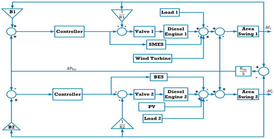
Figure 1.
The first hybrid power system studied.
In this system configuration, the wind turbine in Area 1 and the PV system in Area 2 each supply approximately 25% of the total system demand, with their respective energy storage systems sized to match their generation capacity. The diesel generators in both areas share the remaining demand equally. All system components are modeled as linear first-order transfer functions, as summarized in Table 2 [48]. This system serves as the benchmark platform to assess the proposed control strategy’s performance relative to conventional approaches.

Table 2.
System model transfer functions and parameters [48].
2.1.1. BES Model
The (BES) unit functions by storing energy through chemical processes and subsequently delivering it as electrical power. To achieve this, the BES requires integration with both a charging system and an inverter to facilitate the conversion from direct current (DC) to alternating current (AC) [48]. In this study, a fast-responding BES type is considered. Accordingly, its dynamic behavior is represented using a first-order transfer function characterized by a gain of 1.8 and a time constant set to zero, as formulated below:
2.1.2. SMES Model
The (SMES) system retains energy in the form of a magnetic field generated by circulating (DC) through a superconducting coil, which is maintained at a temperature below the material’s critical superconducting point. To function properly, the SMES unit must be equipped with both an inverter and a cryogenic refrigeration system to sustain the required low-temperature environment. The amount of magnetic energy stored, denoted as (E), and the corresponding power (P), are calculated using the following expressions, as presented in Equations (2) and (3) [48]:
In this work, the SMES device is represented by a first-order transfer function, characterized by a gain value of 0.98 and a time constant of 0.03 s, as shown below:
2.1.3. Diesel Generator Model
In standalone hybrid microgrid configurations, renewable energy sources are integrated with diesel generators to ensure a stable and reliable electricity supply for isolated loads, as the output from renewables fluctuates depending on weather conditions. Typically, diesel generators are outfitted with valve actuators that adjust engine speed to manage the generated power [48]. Under conditions of high load demand, both the diesel units and energy storage systems work together to fulfill the required energy. In this study, the dynamic behavior of the diesel generators and their associated valve actuators is represented using first-order transfer functions, each with a unity gain and time constants of 0.5 s and 0.05 s, respectively.
2.2. GDB and GRC Modeling and Integration
The governor dead band (GDB) represents an intrinsic physical nonlinearity in power system governors, defined by a specified insensitivity zone where small-frequency deviations do not trigger corrective valve action. This behavior stems from two key mechanisms: (i) mechanical clearances within the valve actuation linkage, introducing inherent backlash, and (ii) intentional signal conditioning to prevent unnecessary control cycling during transients. The resultant time delay degrades LFC performance by introducing phase shift, aggravating power swings, and reducing regulation accuracy.
To realistically represent the practical behavior of a turbine governor, the GDB nonlinearity is embedded within the system model, following the mathematical representation in [42]. This model explicitly incorporates the governor valve’s unresponsive region during minor speed changes. The corresponding governor transfer function, accounting for GDB effects, is given by
where designates the governor’s time constant. The numerator coefficients 0.8 and mathematically encapsulate the dead band’s asymmetric impact on valve actuation dynamics, as formally established in [42]. This nonlinearity is deliberately integrated into the governor module to rigorously evaluate controlled efficacy under non-ideal operating regimes, verifying disturbance resilience against practical electromechanical transients. Furthermore, the generation rate constraint (GRC) represents a physical constraint limiting permissible power output ramp rates. These restrictions arise from inherent thermodynamic limitations, mechanical inertia, and operational safety constraints within turbine systems. GRC specifications typically define upper/lower bounds on the generation rate of change, ensuring operation within feasible engineering margins. Neglecting GRC in dynamic models yields unrealistically rapid power adjustments inconsistent with physical plant behavior.
To address this practical limitation, the linear turbine model (Figure 1) is replaced by the nonlinear representation in Figure 2, incorporating GRC constrained to ±0.05 p.u./s. This formulation employs a saturation element enforcing rate-limited response dynamics, accurately capturing inertial delays and thermodynamic lags. As substantiated in [42], this approach restricts turbine power variations to physically achievable trajectories, precluding artificial performance inflation in simulations.

Figure 2.
A nonlinear turbine model with GRC.
Furthermore, this aspect highlights that GRC integration is crucial for the accurate performance assessment of load frequency controllers. Its exclusion produces overly favorable assessments of transient response and stability. Embedding GRC within the turbine module enables credible analysis of frequency dynamics and tie-line power interchange under realistic disturbance scenarios.
2.3. Hybrid Power System Two
Thermal Generator Model Area 1 comprises a thermal generation system integrating a generator, turbine, governor, and reheater. System parameters are detailed in Appendix A. The transfer functions for each component are defined as follows [49], and the overall system is illustrated in Figure 3.
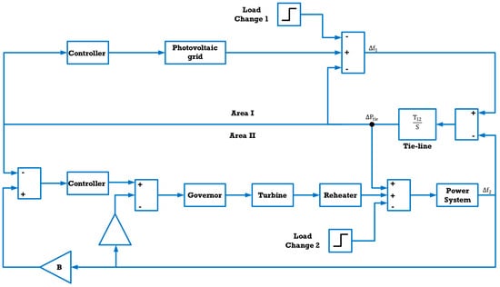
Figure 3.
The second hybrid power system studied.
Governor dynamics:
where Kg is the governor gain, and Tg is the time constant (s).
This first-order transfer function represents the governor’s mechanical power adjustment for frequency regulation.
Turbine dynamics:
where Kt is the turbine gain, and Tt is the time constant (s).
This first-order transfer function characterizes the turbine’s mechanical power output response to demand variations.
The reheater transfer function is defined as
Kr denotes the reheater gain, and Tr represents its associated time constant. This transfer function mathematically characterizes the reheater’s energy transfer dynamics during system transients, encapsulating both the transient response and equilibrium behavior within the power generation process.
The Power System Transfer Function is
Kps denotes the system gain, and Tps represents the inertial time constant (s). This transfer function characterizes the grid’s inertial response to load generation imbalances.
Photovoltaic System Model: The aggregate transfer function representing the integrated photovoltaic system encompassing the solar array, maximum power point tracking (MPPT) converter, inverter, and output filter is defined as follows [49]:
3. The Proposed Controller and Tuning Tool
3.1. Two-Stage Optimized PIDF Plus Fuzzy Architecture
The design in Figure 4 targets superior frequency regulation capabilities and enhanced operational resilience, ensuring stable LFC under varying operating conditions. This hierarchical control structure features two concurrently operated stages, each independently optimized. The primary PID with Filter (PIDF) controller undergoes initial independent optimization via the Particle Swarm Optimization (PSO) algorithm. To further enhance the PIDF’s performance, a secondary controller is integrated. The control signals from both stages are combined to generate the final actuation command. The auxiliary controller is optimized using the Catch Fish Optimization Algorithm (CFOA), with the optimization process constrained by the pre-optimized PIDF parameters obtained in the first stage.

Figure 4.
The developed control scheme.
This hierarchical control design provides enhanced stability, reliability, and robustness, ensuring uninterrupted operation even in the event of partial subsystem failures.
3.2. The Primary PIDF
The Proportional–Integral–Derivative with Filter (PIDF) structure extends conventional PID capability by filtering the derivative path. This architecture directly counters the traditional PID vulnerability to high-frequency disturbances, which can provoke destabilizing actuation. A low-pass filter integrated within the derivative stage attenuates measurement noise, producing deterministic control signals. Enhanced disturbance immunity follows, crucially stabilizing systems operating under stochastic loads. Where conventional PID controllers misinterpret noise as process dynamics, PIDF preserves response fidelity to actual plant behavior. The filter coefficient introduces supplementary design freedom, enabling refined transient shaping in noise-corrupted regimes—a domain where standard PID exhibits inherent limitations. Empirical results confirm PIDF’s suppression of overshoot and oscillatory modes, yielding accelerated settling and rigorous stability margins. These attributes designate PIDF as the preferred solution for high-integrity control applications. The governing transfer function is
with KP, Ki, Kd, and KF representing proportional, integral, derivative, and filter gains. Parameter optimization employs Particle Swarm Optimization (PSO), detailed subsequently.
3.3. PIDF Plus Fuzzy Logic Control with FOPI–FOPD
This research focuses on strengthening the principal PIDF controller through complementary control method integration to determine the optimal (LFC) configuration. Fuzzy Logic Control (FLC) maintains robust operation across diverse power system conditions, serving as an established intelligent technique that delivers consistent performance enhancements. Therefore, the primary PIDF controller receives augmentation via FLC implementation, elevating the overall frequency regulation capability. Figure 5 displays this integrated architecture.
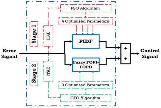
Figure 5.
The PIDF integrated with Fuzzy FOPI–FOPD for LFC.
The PSO algorithm first optimizes the PIDF controller gains. A Fuzzy FOPI–FOPD controller is then integrated into this control scheme. This FLC processes two normalized inputs: the error signal and its time derivative. Normalization uses scaling factors K1 and K2, respectively, where K1 corresponds to the proportional gain KP and scales the error input, K2 corresponds to the derivative gain Kd and scales the first-order derivative of the error, and K3 corresponds to the fractional derivative order (μ). A single output from this fuzzy controller merges with the PIDF structure. Specifically, the Fuzzy FOPI–FOPD output combines with the primary PIDF output to produce the final composite control signal. The transfer function of the proposed controller is outlined in Equations (12) and (13).
PSO was chosen for the PIDF stage because it provides fast and reliable convergence in smooth, low-dimensional search spaces. In contrast, the fuzzy fractional-order compensator operates in a highly nonlinear, multi-modal domain, where CFOA’s balanced exploration and exploitation enhance robustness under GRC and GDB effects. Employing separate optimizers prevents error propagation between heterogeneous components and improves reproducibility compared to a unified approach. This hybrid design exploits both the adaptive nature of fuzzy logic and the deterministic behavior of the PIDF framework, enhancing overall performance.
Structural simplicity and efficiency guide the implementation of the FLC. It utilizes five trapezoidal and triangular membership functions for all linguistic input/output variables. Figure 6 labels these as Negative Big (NB), Negative Small (NS), Zero (Z), Positive Small (PS), and Positive Big (PB). The operation relies on a fuzzy rule base containing 25 conditional statements (Table 3).
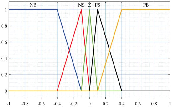
Figure 6.
The membership functions of the fuzzy controller.

Table 3.
The rule base of the FLC component.
To optimize the gain parameters K1, K2, K3, Kp, Ki, Kd, λ, and μ, the CFO algorithm is employed. This process incorporates the PIDF controller’s pre-optimized gains. Crisp input data undergo fuzzification via the Mamdani inference method, resulting in fuzzy linguistic variables. For defuzzification, the centroid technique determines the final control signal. This real-valued output is derived by determining the centroid of the combined output fuzzy set.
3.4. The Suggested Tuning Tool: PSO Algorithm
The primary PIDF controller undergoes precise tuning via Particle Swarm Optimization (PSO), a population-based metaheuristic derived from collective biological phenomena observed in avian flocks and fish schools. The algorithm initializes a solution representing particles that traverse multidimensional search spaces defined by the controller gain parameters. During iterative optimization cycles, trajectory updates synthesize each particle’s historical optimum (pbest) with the swarm’s best global solution (gbest). Specifically, velocity and position adjustments incorporate weighted contributions from individual experience and collective swarm intelligence. This bio-inspired mechanism maintains a critical equilibrium between exploration (diversified global search) and exploitation (local solution refinement), thereby facilitating efficient navigation of non-convex optimization landscapes common in control engineering applications. Through continuous self-learning (cognitive adaptation) and social learning (swarm knowledge exchange) processes, PSO dynamically refines parameter sets to ensure robust controller performance under complex dynamic conditions, including nonlinear plant dynamics and disturbance rejection scenarios. The theoretical foundations of this approach are detailed in [50]. Table 4 specifies the applied PSO configuration for gain optimization.

Table 4.
The PSO parameters.
- ⮚
- Particle Numbers: 50 solutions, governing the swarm size to modulate solution diversity and computational burden.
- ⮚
- Inertia weight: Linearly decreases from Wmax = 1.2 (preserving momentum for global exploration) to Wmin = 0.2 (intensifying local exploitation).
- ⮚
- Cognitive coefficient: C1 = 1.2 (attraction to personal best positions).
- ⮚
- Social coefficient: C2 = 1.2 (attraction to swarm optimal solutions).
- ⮚
- Velocity constraints: Confined to ±0.2 (ub − lb) (20% of design variable bounds), preventing oscillatory divergence while maintaining search efficacy.
- ⮚
- Termination criterion: 100 iterations.
3.5. The Suggested Tuning Tool: CFO Algorithm
The Catch Fish Optimization Algorithm (CFOA) is a metaheuristic optimization technique inspired by traditional fishing practices, where fishermen are modeled as autonomous search agents. The algorithm operates through two main behavioral phases: the exploration phase, where agents conduct an independent search to locate promising regions, and the exploitation phase, where agents coordinate collective encirclement to refine solutions near identified optima. CFOA transitions adaptively between these modes using a stochastic capture rate coefficient (α), balancing diversification and intensification. Importantly, CFOA has been demonstrated in recent studies [42] to be particularly effective for tuning controllers under nonlinear elements, such as GRC and GDB, due to its robust balance between exploration and exploitation. This evidence strongly supports its suitability for the present work, where nonlinearities play a central role. To maintain a reasonable computational overhead during the tuning process, the algorithm’s population size and iteration count were set to 50 and 100, respectively. A detailed elaboration of the CFOA, encompassing its operational principles, procedural flowchart, and mathematical model, can be found in [42,51].
- (1)
- Exploration Phase
In this phase, the algorithm emulates the early-stage behavior of fishermen individually searching for fish-rich zones. Each agent employs targeted seeking and hydrodynamic disturbance tactics to maximize detection. As resource availability changes, agents gradually shift from individual to group-based strategies.
- ⮚
- Independent Search: Agents prioritize personal search efforts, generating disturbances to reveal hidden opportunities.
- ⮚
- Assess Capture Rate (α): A stochastic threshold determines whether agents continue exploring independently or transition to coordinated behavior.
- ⮚
- Update Positions: Based on local success and observed patterns, agents adjust positions dynamically, refining trajectories or relocating as needed.
- (2)
- Exploitation Phase
In this phase, fishermen collaborate to intensify the search near identified optima. Agents organize spatially, combining driving and encircling maneuvers to maximize capture efficiency.
- ⮚
- Group Formation: Agents cluster in small groups (typically 3–4) around target areas, establishing a centroid reference.
- ⮚
- Coordinated Encirclement: Groups apply Gaussian distributed spatial patterns, with central agents focusing on core targets and peripheral agents intercepting escape paths.
- ⮚
- Global Best Referencing: Position updates are fine-tuned relative to the global best solution, with displacement magnitudes adapting over time to improve precision.
Collectively, these mechanisms enable CFOA to effectively balance exploration and exploitation, critically influencing convergence speed and solution accuracy.
3.6. Cost Function
In control theory, establishing equilibrium between rapid dynamic response and robust system stability constitutes a fundamental design challenge. These performance objectives frequently exhibit inherent conflict: optimizing transient speed often undermines stability margins, while excessive stabilization typically slows the response. Consequently, effective control architectures must navigate this trade-off through judicious controller selection and rigorous minimization of a defined cost function, frequently employing advanced optimization methodologies.
Common performance indices for control systems include the Integral of Time-weighted Absolute Error (ITAE), Integral of Squared Error (ISE), Integral of Time-weighted Squared Error (ITSE), and Integral of Absolute Error (IAE). Among these, ISE and ITAE are predominantly utilized within the literature due to their demonstrably superior performance characteristics relative to IAE and ITSE alternatives.
The ISE criterion computes the time integral of squared error, imposing quadratic penalties that disproportionately weight large magnitude errors. This formulation ensures aggressive attenuation of significant deviations but exhibits tolerance toward minor persistent errors. Consequently, IS-optimized systems typically achieve a rapid initial response at the expense of sustained low-amplitude oscillatory behavior during settling. Conversely, the ITAE criterion evaluates the time integral of the absolute error multiplied by time, thereby assigning increasing weight to errors that persist over extended durations. This temporal weighting generally yields systems with accelerated settling times and enhanced transient performance relative to ISE-based tuning approaches.
Within this study, the controller parameters for load frequency control (LFC) applications undergo two-stage optimizations utilizing the (PSO) and (CFOA) algorithms. This optimization framework explicitly minimizes the ITAE objective function, formally expressed mathematically as
4. Results and Discussion
This research was conducted using MATLAB R2024a, with the PSO and CFOA algorithms implemented in standalone. m files to enable precise and flexible tuning of the proposed controller parameters. The LFC system, together with the hybrid PIDF + Fuzzy FOPI–FOPD controller, was fully designed within the Simulink environment to ensure accurate representation of system dynamics and control interactions. The controller’s performance was tested on two different hybrid power system models combining renewable and conventional sources, with the objective of evaluating its effectiveness in improving transient response, reducing steady state errors, and maintaining system stability under diverse operating conditions. All numerical results are expressed in per-unit (p.u.) values, consistent with standard practice in LFC studies, ensuring that the reported improvements reflect relative performance within the per-unit framework rather than absolute physical magnitudes.
4.1. Effectiveness Analysis
4.1.1. First Hybrid Power System Studied
To validate the effectiveness of the proposed control approach, the results were compared with those from literature methods, specifically PIDF controllers using COR and MPA [48]. The PIDF gains used for these comparisons are provided in Table 5.

Table 5.
Optimal PIDF parameters from the literature.
The tuning procedure was completed in two stages. Initially, the PSO algorithm obtained the optimal parameters for the primary PIDF controller. The convergence curve for this optimization is presented in Figure 7, and the optimal PIDF controller values are illustrated in Table 6. Subsequently, the CFOA algorithm optimized the Fuzzy FOPI–FOPD controller parameters separately. This optimization utilized the optimal PIDF controller values established in the first stage. The CFOA algorithm’s convergence curve for tuning the Fuzzy FOPI–FOPD controller is also shown in Figure 7, with the optimal controller values detailed in Table 7.
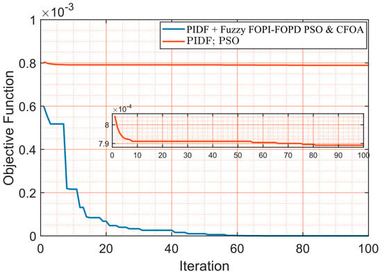
Figure 7.
The convergence curves of PSO and CFO algorithms.

Table 6.
The optimal parameters of the PIDF controller.

Table 7.
The optimal parameters of the Fuzzy-FOPI–FOPD controller.
The two-stage optimization approach ensures a systematic and robust tuning process. The PSO algorithm first optimizes the primary PIDF controller parameters. Subsequently, the CFOA algorithm tunes the advanced Fuzzy FOPI–FOPD controller. This methodology enhances the overall performance of the LFC system. It also demonstrates the effectiveness of the proposed hybrid control strategy in achieving superior dynamic response and stability compared to existing literature methods. The dynamic and steady-state performance of the LFC system was quantitatively assessed using overshoot (OS), undershoot (US), and settling time (ST) metrics for Area 1 frequency deviation (Δf1), Area 2 frequency deviation (Δf2), and tie-line power deviation (ΔPtie). Additionally, the Integral of Time-weighted Absolute Error (ITAE) was computed to evaluate overall control precision. Table 8 summarizes these quantitative results for the proposed PIDF + Fuzzy FOPI–FOPD controller and comparative schemes, including PIDF controllers optimized using PSO, MPA, and COR algorithms. Figure 8 depicts the dynamic response profiles of Δf1, Δf2, and ΔPtie under a 5% step load disturbance applied to Area 1 only, illustrating the superior transient suppression and faster convergence of the proposed control approach relative to the benchmarked methods. The proposed PIDF + Fuzzy FOPI–FOPD controller demonstrates superior performance across all evaluated metrics, achieving the fastest settling time (ST = 0.0405 s) and the lowest ITAE value (0.0000001608), alongside minimal overshoot (OS = 4.7885 × 10⁻⁶) and undershoot (US = −8.94 × 10⁻⁶) in Δf1, (OS = 1.7310 × 10⁻¹⁰, US = −5.5804 × 10⁻⁹, ST = 3.1315 s) in Δf2, and (OS = 3.6495 × 10⁻⁹, US = −1.17 × 10⁻⁷, ST = 3.1511 s) in ΔPtie. This highlights its exceptional ability to suppress oscillations, accelerate convergence, and minimize cumulative tracking errors under a 5% step load disturbance applied to Area 1. In contrast, the PIDF + PSO controller exhibits slightly higher ST (8.5606 s in Δf1, 8.7889 s in Δf2, 8.8000 s in ΔPtie) and ITAE (0.0007891), though it achieves competitive OS (9.3999 × 10⁻⁶) and US (–2.30 × 10⁻⁵) in Δf1. Conventional PIDF controllers optimized using COR and MPA show markedly degraded performance, with elevated overshoot (e.g., PIDF–MPA: OS = 8.0426 × 10⁻⁶ in Δf1) and prolonged settling times (e.g., PIDF–MPA: ST = 6.7298 s in Δf1, 11.0128 s in Δf2, 11.0139 s in ΔPtie). Notably, the PIDF–PSO controller achieves a balanced ST and OS, yet its ITAE remains substantially higher than the proposed hybrid architecture. These findings underscore the efficacy of integrating fuzzy logic with advanced fractional-order PIDF structures to enhance dynamic responsiveness and stability in LFC systems, outperforming both classical and metaheuristic optimized PIDF designs.

Table 8.
The characteristics of the testbed system with different control techniques.
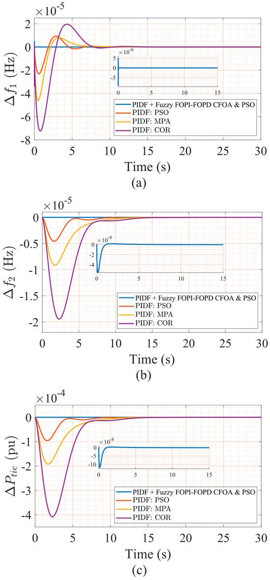
Figure 8.
(a) The frequency deviation in Area 1, (b) frequency deviation in Area 2, and (c) tie-line power deviation for 5% step load perturbation using different algorithms.
Additionally, beyond standard performance assessment, a reliability test evaluated the structural robustness of the proposed two-stage controller under partial failures. While enhancing overall system performance, the hybrid controller employs a primary–secondary structure: the PIDF controller constitutes the primary layer, while the fuzzy FO-PI–FOPD module serves as an auxiliary compensator. To assess dependability, the fuzzy layer was deliberately deactivated, allowing the system to operate exclusively under PIDF control. As depicted in Figure 8a–c, the PIDF loop alone sustained fundamental frequency regulation without inducing instability, thereby demonstrating base controller reliability during degraded operation. However, this fallback mode incurred noticeably increased overshoot, prolonged settling times, and heightened tie-line deviations, highlighting the fuzzy compensator’s essential contribution to response refinement.
The superiority of the hybrid PIDF + Fuzzy FOPI–FOPD controller arises from the complementary interaction of its two layers. The PIDF stage filters high-frequency noise and enhances transient damping, resulting in stable baseline regulation. The Fuzzy FOPI–FOPD layer introduces adaptive nonlinear compensation through fuzzy inference and fractional-order dynamics, balancing integral accumulation with derivative anticipation. This synergy accelerates stabilization, suppresses OS and US, reduces ST, and achieves a lower ITAE. Overall, the architecture integrates deterministic filtering with adaptive fractional compensation, delivering robust and precise frequency regulation under diverse operating conditions.
These findings confirm the controller’s structural resilience under partial failure while reinforcing closed-loop stability across operating conditions. As evidenced by the transient profiles in Figure 8a–c and the numerical synthesis in Table 6 and Table 7, the complete configuration achieves rapid stabilization, reduced deviation magnitudes, and minimized oscillatory behavior, outperforming conventional approaches outlined in the prior literature. These results underscore its practical viability for real-world LFC applications subject to load disturbances.
4.1.2. Second Hybrid Power System Studied
To validate the versatility of the proposed control scheme, the dual-stage PIDF + Fuzzy FOPI–FOPD controller was deployed on a second hybrid power system model. This model features a distinct configuration from the original benchmark, while maintaining equivalent control objectives and evaluation criteria. Without structural or parametric modifications, identical testing protocols were executed. A 10% step load disturbance was simultaneously applied to Areas One and Two to evaluate compound disturbance management across interconnected regions. The controller maintained robust performance across all metrics, including frequency regulation, settling time, and tie-line power stabilization. These outcomes confirm the scheme’s adaptability and operational resilience across diverse hybrid power system architectures. To validate the effectiveness of the proposed control approach, results were benchmarked against existing literature methods—specifically PI controllers using FA and GA [49]. The PI gains for these comparisons are summarized in Table 9.

Table 9.
Optimal PI parameters from the literature.
The controller parameters for the second system were optimized independently using the same two-stage procedure: PSO for PIDF tuning, followed by CFOA for refining the Fuzzy FOPI–FOPD compensator. This process yielded a distinct set of gains suitable for the dynamic characteristics of the second hybrid model.
The optimized gain values are presented in Table 10 and Table 11, while the corresponding dynamic performance indicators—including overshoot (OS), undershoot (US), settling time (ST), and the Integral of Time-weighted Absolute Error (ITAE)—are summarized in Table 12.

Table 10.
The optimal parameters of the PIDF controller.

Table 11.
The optimal parameters of the Fuzzy FOPI–FOPD controller.

Table 12.
The characteristics of the testbed system with different control techniques.
As depicted in Figure 9a–c, the proposed controller achieves superior transient behavior compared to benchmark PI controllers optimized via FA and GA. Specifically, it demonstrates faster settling, reduced peak deviations, and enhanced tie-line stabilization under simultaneous 10% step load disturbances in both areas.
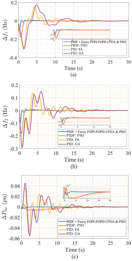
Figure 9.
(a) The frequency deviation in Area 1, (b) frequency deviation in Area 2, and (c) tie-line power deviation for a 10% step load perturbation using different algorithms.
These results reinforce the robustness of the proposed control framework and confirm its ability to deliver consistent high-performance frequency regulations across different hybrid power system configurations. The proposed PIDF + Fuzzy FOPI–FOPD controller achieves superior dynamic performance across all metrics under simultaneous 10% step load disturbances in both areas. As Table 9 shows, it attains the fastest (ST = 5.0958 s for Δf1, 6.3095 s for Δf2, 5.7514 s for ΔPtie), lowest (OS = 0.0095, US = −0.1131 in Δf1), and minimal ITAE (0.2683). These results demonstrate effective oscillation suppression, rapid convergence, and precise frequency regulation in the presence of compound disturbances. Conversely, the PIDF + PSO controller exhibits moderately delayed dynamics (ST = 6.4480 s in Δf1, 5.6136 s in Δf2) and elevated ITAE (0.8844) despite comparable Δf1 (OS = 0.0094). Traditional PIDF controllers (FA/GA tuned) show significantly compromised performance, with substantially increased (PIDF–GA: OS = 0.1759 in Δf1) and extended (e.g., ST = 18.0475 s in Δf1, 19.8593 s in tie-line).
Figure 9a–c illustrates the hybrid controller’s smoother transient profiles, effective inter-area oscillation suppression, and accelerated frequency restoration versus benchmarks. These outcomes validate the robustness and enhanced control efficacy of the dual-stage strategy in frequency/tie-line regulation under multi-area disturbance scenarios.
4.2. Robustness Analysis
4.2.1. Robustness Against Nonlinearities
This section thoroughly examines the combined impact of Generation Dead Band (GDB) and generation rate constraint (GRC) nonlinearities on dynamic LFC performance in the first hybrid power system model during rigorous robustness assessment. The GDB was modeled using Equation (5), while the GRC nonlinearity was integrated as depicted in Figure 2. Both nonlinear components were embedded within the Figure 1 architecture. To isolate GDB/GRC dynamics, all controller gains, including the proposed hybrid scheme and conventional controllers, were preserved from prior optimizations under nominal conditions without returning. This approach ensures that performance deviations stem solely from GDB/GRC inclusion. Figure 10a–c depict the transient responses of Δf1, Δf2, and ΔPtie under a 5% step load disturbance in Area 1, with quantitative metrics outlined in Table 13. Benchmark controllers exhibit significant degradation, characterized by increased overshoot, prolonged settling times, and elevated ITAE values. Conversely, the proposed PIDF + Fuzzy FOPI–FOPD controller maintains stable frequency regulation and effective damping with minimal nonlinearity sensitivity. These results demonstrate the control architecture’s structural resilience and confirm its viability for real-world LFC implementations involving GDB/GRC non-idealities.
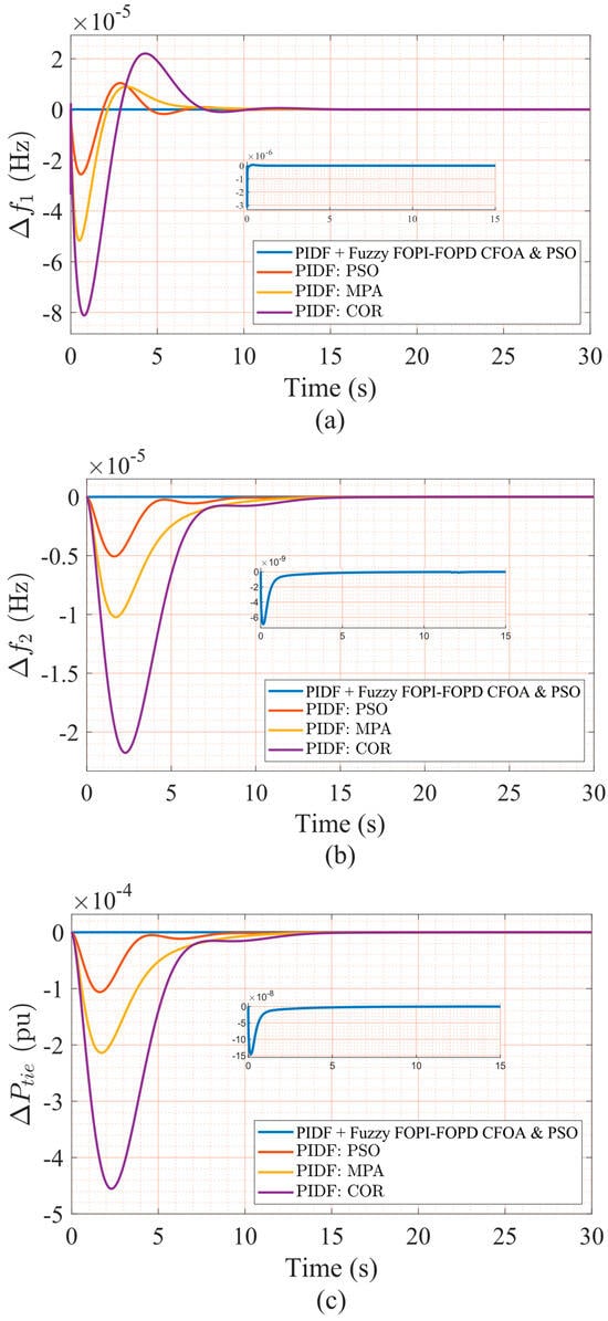
Figure 10.
(a) The frequency deviation in Area 1, (b) frequency deviation in Area 2, and (c) tie-line power deviation.

Table 13.
The characteristics of the testbed system with different control techniques under the impact of GDB and GRC.
Notably, following the integration of nonlinearities (GDB and GRC), Table 13 clearly demonstrates a substantial, measurable, and quantifiable degradation in the dynamic performance of conventional PIDF controllers optimized via PSO, MPA, and COR. These classical control schemes experience amplified OS and US, prolonged ST, and significantly elevated ITAE values, all of which indicate a marked reduction in robustness, adaptability, and reliable dynamic control fidelity under challenging, non-ideal operating conditions. For example, PIDF–PSO records an OS of 1.0409 × 10⁻⁵ and ST of 8.5716 s in Δf1, reflecting moderate damping inadequacy and delayed convergence under perturbations. More critically, PIDF–MPA and PIDF–COR exhibit greater US values (−5.17 × 10⁻⁵ and −8.11 × 10⁻⁵, respectively), accompanied by slower frequency stabilization, reduced tracking accuracy, and diminished recovery across all critical control channels. The corresponding ITAE values further highlight this degradation, with PIDF–PSO reaching 0.002843, PIDF–MPA reaching 0.004963, and PIDF–COR peaking at 0.006218—indicating poor disturbance rejection capability and excessive control energy consumption during regulation over extended simulation periods. In stark contrast, the proposed hybrid controller—PIDF + Fuzzy FOPI–FOPD—retains exceptional resilience and dynamic consistency under the same nonlinear perturbations. It achieves significantly improved performance metrics, including minimal OS (4.7885 × 10⁻⁶) and US (−8.94 × 10⁻⁶), an ultra-short ST of 0.3527 s in Δf1, and the lowest recorded ITAE of 0.000002835 among all tested approaches. This performance clearly reflects the hybrid scheme’s enhanced oscillation suppression, precise tracking, and superior control energy efficiency. Additionally, the controller consistently exhibits robust, stable damping characteristics across Δf1, Δf2, and tie-line deviations without divergence or instability, regardless of the compounded effects introduced by GDB and GRC. These comprehensive outcomes definitively validate the proposed architecture’s structural robustness and confirm its superiority in maintaining reliable frequency regulation and secure tie-line power exchange even under highly nonlinear, uncertain, and demanding operating conditions.
4.2.2. Robustness Against Parametric Uncertainty
System parameters—including the damping coefficient, speed regulation constant, inertia constant, and governor dynamics—exhibit inherent variability due to environmental and operational fluctuations, which can compromise the performance of closed-loop frequency control systems. To rigorously assess the robustness of the proposed strategy under such uncertainties, seven test scenarios were conducted by applying ±40% variations to key parameters: the area swing time constant (TAS), frequency bias factor (B), actuator time constant (TV), area swing gain (KAS), diesel governor time constant (TDG), and speed regulation constant (R), as shown in Table 14. These deviations were uniformly imposed across both areas of the interconnected power system, and the nominal values were taken from Table 2. The performance of the PIDF + Fuzzy FOPI–FOPD controller was benchmarked against that of the PIDF-PSO controller and other reference controllers from the literature. The optimal gains, which were determined under nominal conditions, remained fixed throughout all scenarios without returning, thereby ensuring a rigorous robustness evaluation.

Table 14.
Different scenarios of system parametric uncertainties.
Figure 11, Figure 12, Figure 13, Figure 14, Figure 15, Figure 16 and Figure 17 present frequency deviations in Areas One and Two and tie-line power deviations across seven robustness test scenarios, conducted under a 5% step load disturbance applied to Area One only. These confirm that the proposed PIDF + Fuzzy FOPI–FOPD controller consistently sustains stable, bounded responses despite ±40% variations in critical parameters, including swing gain (KAS), swing time constant (TAS), frequency bias (B), diesel governor time constant (TDG), and speed regulation constant (R). As detailed in Table 15, the controller achieves extremely low overshoot and undershoot values (typically in the 10−6 to 10−7 range) while maintaining rapid settling times—under 0.07 s for Δf1 and approximately 3.2 s for Δf2—even under severe conditions. For instance, Case 1 (+40% TAS) maintained Area One OS at 3.446 × 10⁻⁶, US at −7.616 × 10⁻⁶, ST at 0.0485 s, and ITAE of 1.497 × 10⁻⁷. Similarly, Case 5 (+40% B) preserved stable dynamics with only minor increases in ST and US, resulting in an ITAE of 1.862 × 10⁻⁷, compared to 0.005569 for PIDF–COR. Even in Case 7 (a combined −40% reduction in R and KAS, with +40% in TAS), the proposed controller sustained robust performance, achieving an ST of 0.0698 s in Area One and an ITAE of 1.867 × 10⁻⁷, outperforming all competing strategies. Notably, the proposed controller operated with fixed nominal condition gains and no retuning across all test cases. In contrast, controllers such as PIDF–PSO and PIDF–COR exhibited substantial performance degradation under the same conditions of uncertainty. For example, in Case 3, PIDF–PSO registered an OS of 1.501 × 10⁻⁵ and a ST of 8.2576 s in Area One, over 160 times slower than the proposed method. These findings clearly demonstrate the superior robustness and reliability of the PIDF + Fuzzy FOPI–FOPD controller, highlighting its suitability for real-world LFC systems subject to parameter uncertainties where controller retuning is impractical.
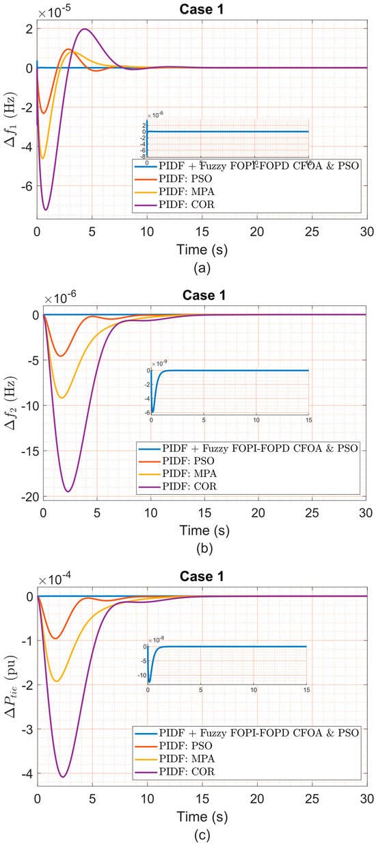
Figure 11.
(a) Δf1, (b) Δf2, and (c) ΔPtie under Case 1 variation.
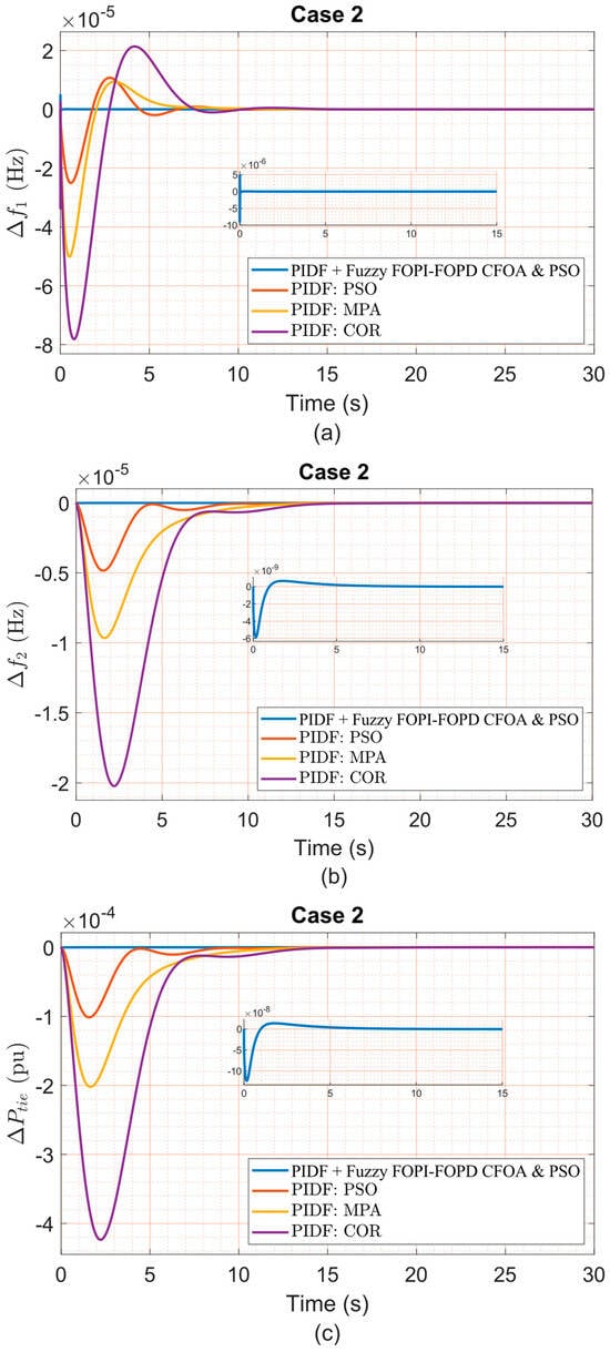
Figure 12.
(a) Δf1, (b) Δf2, and (c) ΔPtie under Case 2 variation.
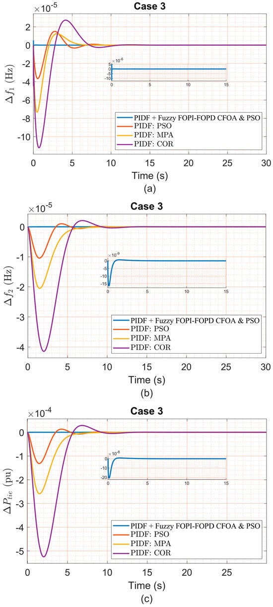
Figure 13.
(a) Δf1, (b) Δf2, and (c) ΔPtie under Case 3 variation.
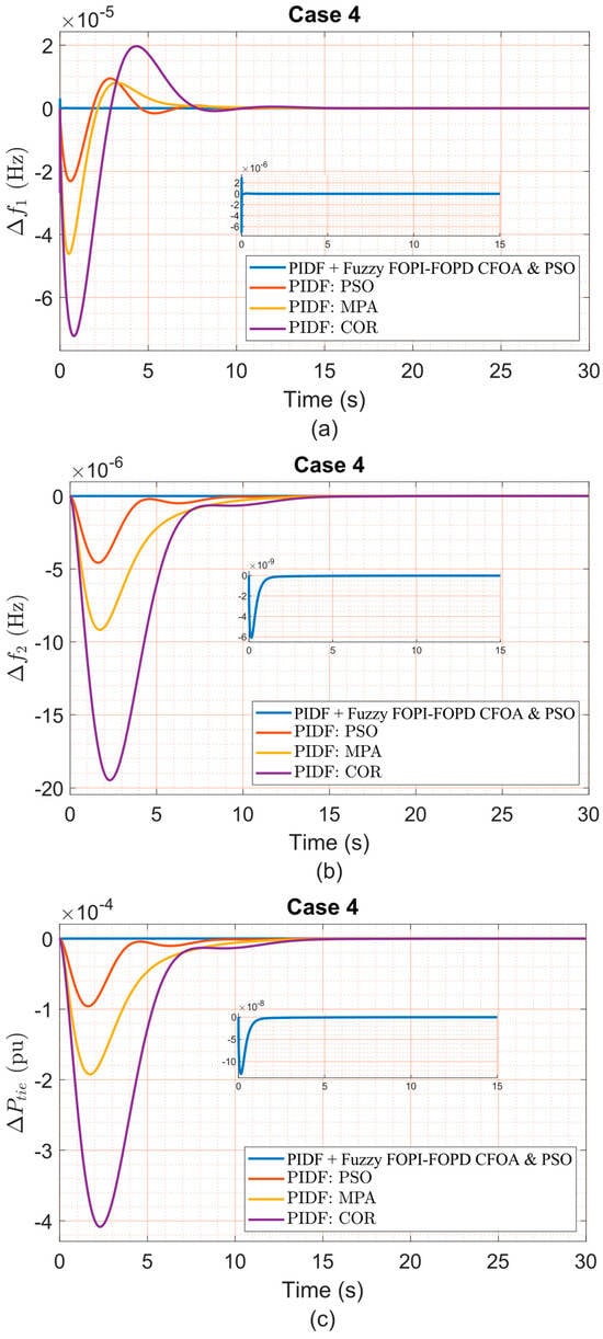
Figure 14.
(a) Δf1, (b) Δf2, and (c) ΔPtie under Case 4 variation.
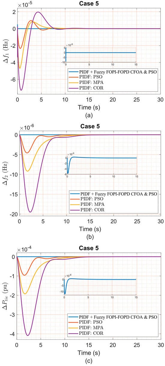
Figure 15.
(a) Δf1, (b) Δf2, and (c) ΔPtie under Case 5 variation.
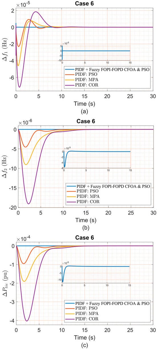
Figure 16.
(a) Δf1, (b) Δf2, and (c) ΔPtie under Case 6 variation.
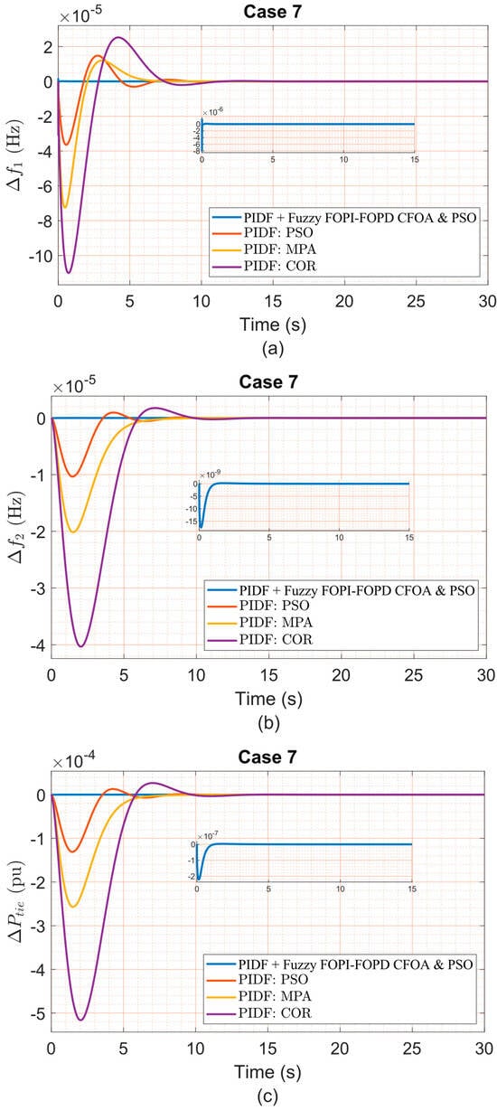
Figure 17.
(a) Δf1, (b) Δf2, and (c) ΔPtie under Case 7 variation.

Table 15.
The dynamic response of the system under different parametric uncertainty cases.
4.3. Effect of Random Load Disturbance
To evaluate the robustness of the proposed PIDF + Fuzzy FOPI–FOPD controller under time-varying demand patterns, a three-step random load disturbance was applied exclusively to Area One. The disturbance profile, depicted in Figure 18, includes a sequential shift from 0.01 p.u. to 0.025 p.u. at 5 s, followed by a drop to 0.005 p.u. at 15 s, simulating abrupt and asymmetric load changes over a 30-s interval.
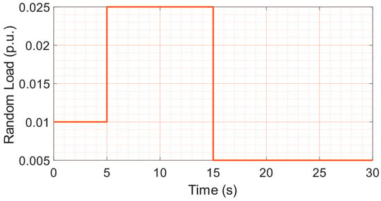
Figure 18.
The random load profile.
Under this non-periodic and unpredictable excitation, the proposed controller demonstrated strong adaptability and effective disturbance rejection. Performance was benchmarked against PIDF–PSO, PIDF–MPA, and PIDF–COR controllers, all implemented under identical system configurations. Across all frequency and tie-line deviation metrics (Δf1, Δf2, and ΔPtie), the proposed scheme maintained the lowest OS and US while delivering the fastest ST. Its ability to accommodate sudden load reductions and surges without destabilizing the system confirms the high disturbance tolerance and robustness of the hybrid control structure. Figure 19 illustrates the corresponding dynamic responses in Area 1, Area 2, and the tie-line, confirming the proposed controller’s superior transient behavior.
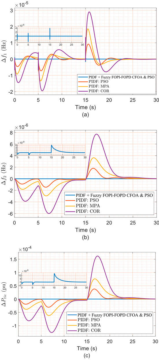
Figure 19.
The dynamic response under random load disturbance in Area 1. (a) Δf1, (b) Δf2, and (c) ΔPtie.
This test scenario reflects real-world operating conditions, such as renewable integration or industrial load switching, and reinforces the viability of the proposed controller in practical LFC deployments.
The proposed PIDF + Fuzzy FOPI–FOPD control scheme demonstrates exceptional effectiveness in mitigating random load disturbances, thereby ensuring sustained system stability and reliable dynamic performance across diverse operating conditions. In contrast, conventional controllers, including the PSO-tuned PIDF and PIDF structures optimized by MPA and COR, exhibit reduced resilience in handling time-varying demand patterns, highlighting their limited adaptability to rapidly changing loads. The experimental findings confirm the superior robustness of the hybrid controller, validating its ability to manage sudden and stochastic load variations without compromising operational reliability. These results provide strong evidence of the controller’s capacity to maintain performance standards under realistic load uncertainties, reinforcing its suitability for practical deployment in modern LFC applications.
5. Conclusions and Future Work
This work presents an innovative hybrid control strategy designed to enhance the reliability and dynamic performance of load frequency control (LFC) in multi-area power networks. The developed methodology combines a classical Proportional–Integral–Derivative with Filter (PIDF) controller with a Fuzzy Fractional-Order PI–PD (FOPI–FOPD) module in a parallel two-stage configuration to ensure robust frequency regulation. In the first stage, Particle Swarm Optimization (PSO) is used to tune the PIDF controller. In the second stage, the Catch Fish Optimization Algorithm (CFOA) is employed to optimize the parameters of the Fuzzy FOPI–FOPD controller. This independent tuning ensures that each component operates optimally and can maintain functionality under partial failure conditions.
Simulation results confirm that the hybrid PIDF + Fuzzy FOPI–FOPD controller achieves superior performance across key frequency metrics, including minimized OS, reduced US, and faster ST, significantly outperforming benchmark strategies such as PIDF–PSO, PIDF–MPA, and PIDF–COR under identical nonlinear conditions. Robustness analyses further validate the controller’s resilience against parametric variations and nonlinear effects such as governor dead band (GDB) and generation rate constraint (GRC). These findings demonstrate the effectiveness and adaptability of the proposed dual-stage controller in modern LFC applications with high renewable energy integration.
Future work may extend this framework to multi-area systems with high renewable integration and broader dynamic profiles. Advanced intelligent controllers, such as Fractional-Order PID (FOPID), Tilt–Integral–Derivative (TID), and adaptive neuro-fuzzy inference systems (ANFIS), can also be explored in combination with fuzzy logic to enhance flexibility and decision-making capabilities.
On a practical level, future studies should prioritize embedding the proposed dual-stage controller into semi-physical LFC environments using real-time digital platforms, enabling direct interaction with dynamic grid components and communication layers. Such integration will facilitate operational stability verification under real-world uncertainties, including latency, sensor limitations, and controller response delays, within smart grid-aligned infrastructures.
Additionally, extending the modeling scope to incorporate higher-order device dynamics, stochastic representations of renewable energy, and advanced storage behaviors will further enhance the realism, robustness, and field applicability of the proposed control paradigm.
Author Contributions
Conceptualization, M.S. and S.A.; methodology, M.S. and S.A.; software, M.S. and S.A.; validation, M.S., S.A. and F.A.; formal analysis, M.P.; investigation, M.S. and S.A.; resources, M.P.; data curation, F.A.; writing—original draft preparation, M.S., F.A., M.P. and S.A.; writing—review and editing, M.S., F.A., M.P. and S.A.; visualization, M.S., F.A., M.P. and S.A.; supervision, F.A.; project administration, M.P.; funding acquisition, S.A. All authors have read and agreed to the published version of the manuscript.
Funding
This research received no external funding.
Data Availability Statement
The conducted codes and simulations are available upon a reasonable request from the corresponding author.
Acknowledgments
The authors thank Cardiff University, School of Engineering, for paying the APC to publish this manuscript.
Conflicts of Interest
The authors declare no conflicts of interest.
Abbreviations
The following abbreviations are used in this manuscript:
| LFC | Load frequency control. |
| FOPID | Fractional order proportional–integral–derivative. |
| PI | Proportional and integral. |
| FLC | Fuzzy logic controller. |
| CFOA | Catch fish optimization algorithm. |
| ITAE | Integral of time-weighted absolute error. |
| GDB | Governor dead band. |
| GRC | Generation rate constraint. |
| PSO | Particle swarm optimization. |
| GA | Genetic algorithm. |
| ITEA | Integral of time multiplied error in area. |
| ACE | Area control error. |
| MF | Membership function. |
| NB | Negative big. |
| NS | Negative small. |
| Z | Zero. |
| PS | Positive small. |
| PB | Positive big. |
| SLP | Step load perturbation. |
| DG | Distributed generation. |
| BES | Battery energy storage. |
| SMES | Superconducting magnetic energy storage. |
| RES | Renewable energy sources. |
| AVR | Automatic voltage regulator. |
| TLBO | Teaching–learning-based optimization. |
| PIDF | Proportional, integral, derivative with filter. |
| FOPI | Fractional order proportional–integral. |
| FOPD | Fractional order proportional–derivative. |
Appendix A
The system data are as shown below:
TP = 20 s; Tt = 0.3 s; Tr = 10 s; T12 = 0.545 p.u.; Tg = 0.08 s; KP = 120 Hz/p.u MW; B = 0.8 p.u MW/Hz; a12 = −1; R = 0.4 Hz/p.u. MW; Kr1 = 0.33 p.u. MW.
References
- Shouran, M.; Anayi, F.; Packianather, M. A State-of-The-Art Review on LFC Strategies in Conventional and Modern Power Systems. In Proceedings of the 2021 International Conference on Advance Computing and Innovative Technologies in Engineering, ICACITE 2021, Greater Noida, India, 4–5 March 2021; Institute of Electrical and Electronics Engineers Inc.: New York, NY, USA, 2021; pp. 268–277. [Google Scholar] [CrossRef]
- Singh, A.; Yadav, S.; Tiwari, N.; Nishad, D.K.; Khalid, S. Optimized PID controller and model order reduction of reheated turbine for load frequency control using teaching learning-based optimization. Sci. Rep. 2025, 15, 3759. [Google Scholar] [CrossRef] [PubMed]
- El-Rifaie, A.M.; Abid, S.; Ginidi, A.R.; Shaheen, A.M. Fractional Order PID Controller Based-Neural Network Algorithm for LFC in Multi-Area Power Systems. Eng. Rep. 2025, 7, 70028. [Google Scholar] [CrossRef]
- Shah, P.; Agashe, S. Review of fractional PID controller. Mechatronics 2016, 38, 29–41. [Google Scholar] [CrossRef]
- Nassef, A.M.; Abdelkareem, M.A.; Maghrabie, H.M.; Baroutaji, A. Metaheuristic-Based Algorithms for Optimizing Fractional-Order Controllers—A Recent, Systematic, and Comprehensive Review. Multidiscip. Digit. Publ. Inst. 2023, 7, 553. [Google Scholar] [CrossRef]
- Ramesh, M.; Yadav, A.K.; Pathak, P.K. Intelligent adaptive LFC via power flow management of integrated standalone micro-grid system. ISA Trans. 2021, 112, 234–250. [Google Scholar] [CrossRef] [PubMed]
- Dahab, Y.A.; Abubakr, H.; Mohamed, T.H. Adaptive load frequency control of power systems using electro-search optimization supported by the balloon effect. IEEE Access 2020, 8, 7408–7422. [Google Scholar] [CrossRef]
- Van Huynh, V.; Naqvi, S.; Nguyen, B.L.H.; Tran, A.T.; Shim, J.W.; Do, T.D. Robust super-twisting algorithm-based single-phase sliding mode frequency controller in power systems integrating wind turbines and energy storage systems. Sci. Rep. 2025, 15, 19740. [Google Scholar] [CrossRef]
- Deng, Z.; Xu, C.; Huo, Z.; Han, X.; Xue, F. Sliding Mode Based Load Frequency Control and Power Smoothing of Power Systems with Wind and BESS Penetration. Machines 2022, 10, 1225. [Google Scholar] [CrossRef]
- Gude, J.J.; Kahoraho, E.; Etxaniz, J. Practical aspects of PID controllers: An industrial experience. In Proceedings of the 2006 IEEE Conference on Emerging Technologies and Factory Automation, Prague, Czech Republic, 20–22 September 2006; IEEE: New York, NY, USA, 2006; pp. 870–878. [Google Scholar]
- Tuan, D.H.; Nguyen Ngoc Thanh, V.; Nguyen Chi, D.; Pham, V.H. Improving Frequency Control of Multi-Area Interconnected Hydro-Thermal Power System Using PSO Algorithm. Appl. Sci. 2025, 15, 2898. [Google Scholar] [CrossRef]
- Das, D.C.; Roy, A.K.; Sinha, N. GA based frequency controller for solar thermal-diesel-wind hybrid energy generation/energy storage system. Int. J. Electr. Power Energy Syst. 2022, 43, 262–279. [Google Scholar] [CrossRef]
- Munisamy, V.; Sundarajan, R.S. Hybrid technique for load frequency control of renewable energy sources with unified power flow controller and energy storage integration. Int. J. Energy Res. 2021, 45, 17834–17857. [Google Scholar] [CrossRef]
- Fathy, A.; Kassem, A.; Zaki, Z.A. A Robust Artificial Bee Colony-Based Load Frequency Control for Hydro-Thermal Interconnected Power System. Sustainability 2022, 4, 13569. [Google Scholar] [CrossRef]
- Khalil, A.E.; Boghdady, T.A.; Alham, M.H.; Ibrahim, D.K. Enhancing the Conventional Controllers for Load Frequency Control of Isolated Microgrids Using Proposed Multi-Objective Formulation via Artificial Rabbits Optimization Algorithm. IEEE Access 2023, 11, 3472–3493. [Google Scholar] [CrossRef]
- Mohamed, M.A.E.; Jagatheesan, K.; Anand, B. Modern PID/FOPID controllers for frequency regulation of interconnected power system by considering different cost functions. Sci. Rep. 2023, 13, 14084. [Google Scholar] [CrossRef]
- Dahiya, P.; Saha, A.K. Frequency Regulation of Interconnected Power System Using Black Widow Optimization. IEEE Access 2022, 10, 25219–25236. [Google Scholar] [CrossRef]
- Obma, J.; Audomsi, S.; Ardhan, K.; Sa-Ngiamvibool, W.; Chansom, N. Strategic Chess Algorithm-Based PI Controller Optimization for Load Frequency Control in Two-Area Hybrid Photovoltaic– Thermal Power Systems. Int. J. Robot. Control Syst. 2025, 5, 1156–1171. [Google Scholar] [CrossRef]
- Guha, D.; Roy, P.K.; Banerjee, S. Load frequency control of interconnected power system using grey Wolf optimization. Swarm. Evol. Comput. 2016, 27, 97–115. [Google Scholar] [CrossRef]
- Saleh, B.; Yousef, A.M.; Ebeed, M.; Abo-Elyousr, F.K.; Elnozahy, A.; Mohamed, M.; Abdelwahab, S.A.M. Design of PID Controller with Grid Connected Hybrid Renewable Energy System Using Optimization Algorithms. J. Electr. Eng. Technol. 2021, 16, 3219–3233. [Google Scholar] [CrossRef]
- Shafei, M.A.R.; Alzaher, A.N.A.; Ibrahim, D.K. Enhancing load frequency control of multi-area multi-sources power system including conventional and renewable energy units with nonlinearities. Indones. J. Electr. Eng. Comput. Sci. 2020, 19, 108. [Google Scholar] [CrossRef]
- Sharma, A.; Singh, N. Load frequency control of connected multi-area multi-source power systems using energy storage and lyrebird optimization algorithm tuned PID controller. J. Energy Storage 2024, 100, 113609. [Google Scholar] [CrossRef]
- Lalhmangaihzuala, F.; Datta, S.; Lalngaihawma, S.; Ustun, T.S.; Kalam, A. A renewable integrated multi-area system for LFC incorporating electrical vehicle with SoC estimation. Front. Energy Res. 2024, 12, 1508391. [Google Scholar] [CrossRef]
- Sobhy, M.A.; Abdelaziz, A.Y.; Hasanien, H.M.; Ezzat, M. Marine predators algorithm for load frequency control of modern interconnected power systems including renewable energy sources and energy storage units. Ain Shams Eng. J. 2021, 12, 3843–3857. [Google Scholar] [CrossRef]
- Khadanga, R.K.; Kumar, A.; Panda, S. A novel modified whale optimization algorithm for load frequency controller design of a two-area power system composing of PV grid and thermal generator. Neural. Comput. Appl. 2020, 32, 8205–8216. [Google Scholar] [CrossRef]
- Almutairi, S.Z.; Moustafa, G.; Hakmi, S.H.; Shaheen, A.M. Bonobo Optimizer Inspired PI-(1+DD) Controller for Robust Load Frequency Management in Renewable Wind Energy Systems. Int. J. Energy Res. 2025, 2025, 6874402. [Google Scholar] [CrossRef]
- Hasanien, H.M.; El-Fergany, A.A. Salp swarm algorithm-based optimal load frequency control of hybrid renewable power systems with communication delay and excitation cross-coupling effect. Electr. Power Syst. Res. 2019, 176, 105938. [Google Scholar] [CrossRef]
- Patel, S.; Mohanty, B.; Simhadri, K.S. Frequency Stability Analysis of Power System Using Competition Over Resources Technique Optimized PIDA Controller. Iran. J. Sci. Technol. Trans. Electr. Eng. 2022, 46, 57–75. [Google Scholar] [CrossRef]
- Elsaied, M.M.; Attia, M.A.; Mostafa, M.A.; Mekhamer, S.F. Application of Different Optimization Techniques to Load Frequency Control with WECS in a Multi-Area System. Electr. Power Compon. Syst. 2018, 46, 739–756. [Google Scholar] [CrossRef]
- Qingchao, L.; Jingjuan, W.; Qiang, L.; Fuling, W.; Yuanfang, C. Sediment Instability Caused by Gas Production from Hydrate-Bearing Sediment in Northern South China Sea by Horizontal Wellbore: Sensitivity Analysis. Nat. Resour. Res. 2025, 34, 1667–1699. [Google Scholar] [CrossRef]
- Li, Q.; Li, Q.; Wang, F.; Xu, N.; Wang, Y.; Bai, B. Settling behavior and mechanism analysis of kaolinite as a fracture proppant of hydrocarbon reservoirs in CO2 fracturing fluid. Colloids Surf. A Physicochem. Eng. Asp. 2025, 724, 137463. [Google Scholar] [CrossRef]
- Izci, D.; Ekinci, S.; Çelik, E.; Bajaj, M.; Blazek, V.; Prokop, L. Dynamic load frequency control in Power systems using a hybrid simulated annealing based Quadratic Interpolation Optimizer. Sci. Rep. 2024, 14, 26011. [Google Scholar] [CrossRef]
- Raju, M.; Saikia, L.C.; Sinha, N. Automatic generation control of a multi-area system using ant lion optimizer algorithm based PID plus second order derivative controller. Int. J. Electr. Power Energy Syst. 2016, 80, 52–63. [Google Scholar] [CrossRef]
- Gupta, D.K.; Dei, G.; Soni, A.K.; Jha, A.V.; Appasani, B.; Bizon, N.; Srinivasulu, A.; Nsengiyumva, P. Fractional order PID controller for load frequency control in a deregulated hybrid power system using Aquila Optimization. Results Eng. 2024, 23, 102442. [Google Scholar] [CrossRef]
- Shouran, M.; Anayi, F.; Packianather, M.; Habil, M. Load frequency control based on the bees algorithm for the great britain power system. Designs 2021, 5, 50. [Google Scholar] [CrossRef]
- Fathy, A.; Rezk, H.; Ferahtia, S.; Ghoniem, R.M.; Alkanhel, R.; Ghoniem, M.M. A New Fractional-Order Load Frequency Control for Multi-Renewable Energy Interconnected Plants Using Skill Optimization Algorithm. Sustainability 2022, 14, 14999. [Google Scholar] [CrossRef]
- Limon, M.F.A.; Upoma, R.S.; Sinha, N.; Swarna, S.R.; Nath, B.K.; Khanum, K.; Rahman, J.; Iqbal, S. Grey wolf optimization-based fuzzy-PID controller for load frequency control in multi-area power systems. J. Autom. Intell. 2025, 4, 145–159. [Google Scholar] [CrossRef]
- Mohanty, D.; Giri, A.; Panda, S. Frequency regulation by optimized fuzzy based self-adaptive virtual inertia control for microgrid with variable renewable penetration. J. Energy Storage 2024, 104, 114433. [Google Scholar] [CrossRef]
- Nayak, P.C.; Prusty, R.C.; Panda, S. Adaptive fuzzy approach for load frequency control using hybrid moth flame pattern search optimization with real time validation. Evol. Intell. 2024, 17, 1111–1126. [Google Scholar] [CrossRef]
- Abdelghany, M.A.; Syam, F.A.; Aly, A.M.; Abido, M.A.; Ibrahim, S.O. Load frequency and virtual inertia control for power system using fuzzy self-tuned PID controller with high penetration of renewable energy. J. Electr. Syst. Inf. Technol. 2024, 11, 50. [Google Scholar] [CrossRef]
- Aljohani, T. Intelligent Type-2 Fuzzy Logic Controller for Hybrid Microgrid Energy Management with Different Modes of EVs Integration. Energies 2024, 17, 2949. [Google Scholar] [CrossRef]
- Almutairi, S.; Anayi, F.; Packianather, M.; Shouran, M. An Innovative LFC System Using a Fuzzy FOPID- Enhanced via PI Controller Tuned by the Catch Fish Optimization Algorithm Under Nonlinear Conditions. Sustainability 2025, 17, 5966. [Google Scholar] [CrossRef]
- Ranjan, M.; Shankar, R. Effect of Electric Vehicles and Renewable Sources on Frequency Regulation in Hybrid Power System Using QOAOA Optimized Type-2 Fuzzy Fractional Controller. Int. J. Fuzzy Syst. 2024, 26, 825–848. [Google Scholar] [CrossRef]
- Elkasem, A.H.A.; Kamel, S.; Khamies, M.; Nasrat, L. Frequency regulation in a hybrid renewable power grid: An effective strategy utilizing load frequency control and redox flow batteries. Sci. Rep. 2024, 14, 9576. [Google Scholar] [CrossRef]
- Jalilian, M.; Rastgou, A.; Kharrati, S.; Hosseini-Hemati, S. Load frequency control resilience of hybrid power system with renewable energy sources and superconducting magnetic energy storage using FO-Fuzzy-PID controller. Results Eng. 2025, 27, 105961. [Google Scholar] [CrossRef]
- Yuan, Z.L.; Zhang, C.K.; Shangguan, X.C.; Fan, Y.L.; He, Y. T-S Fuzzy-Based Load Frequency Control of Multiarea Power System with Hybrid Delays: Performance Analysis and Improvement. IEEE Trans. Fuzzy Syst. 2024, 32, 6939–6950. [Google Scholar] [CrossRef]
- Türk, İ.; Kılıç, H.; Haydaroğlu, C.; Top, A. Robust Load Frequency Control in Hybrid Microgrids Using Type-3 Fuzzy Logic Under Stochastic Variations. Symmetry 2025, 17, 853. [Google Scholar] [CrossRef]
- Yakout, A.H.; Kotb, H.; Hasanien, H.M.; Aboras, K.M. Optimal Fuzzy PIDF Load Frequency Controller for Hybrid Microgrid System Using Marine Predator Algorithm. IEEE Access 2021, 9, 54220–54232. [Google Scholar] [CrossRef]
- SAbd-Elazim, M.; Ali, E.S. Load frequency controller design of a two-area system composing of PV grid and thermal generator via firefly algorithm. Neural. Comput. Appl. 2018, 30, 607–616. [Google Scholar] [CrossRef]
- Shouran, M.; Alsseid, A. Particle Swarm Optimization Algorithm-Tuned Fuzzy Cascade Fractional Order PI-Fractional Order PD for Frequency Regulation of Dual-Area Power System. Processes 2022, 10, 477. [Google Scholar] [CrossRef]
- Jia, H.; Wen, Q.; Wang, Y.; Mirjalili, S. Catch fish optimization algorithm: A new human behavior algorithm for solving clustering problems. Clust. Comput. 2024, 27, 13295–13332. [Google Scholar] [CrossRef]
Disclaimer/Publisher’s Note: The statements, opinions and data contained in all publications are solely those of the individual author(s) and contributor(s) and not of MDPI and/or the editor(s). MDPI and/or the editor(s) disclaim responsibility for any injury to people or property resulting from any ideas, methods, instructions or products referred to in the content. |
© 2025 by the authors. Licensee MDPI, Basel, Switzerland. This article is an open access article distributed under the terms and conditions of the Creative Commons Attribution (CC BY) license (https://creativecommons.org/licenses/by/4.0/).