Abstract
Highway on-ramp merging areas represent critical bottlenecks that significantly impact traffic efficiency and sustainability. This paper proposes a novel Delay-Compensated Merging Control (DCMC) framework that addresses the practical challenges of cloud-based cooperative vehicle control under realistic communication conditions. The system integrates an efficient mixed-integer linear programming (MILP) model for trajectory optimization with a robust two-stage delay compensation mechanism. The MILP model coordinates mainline and ramp vehicles through proactive gap creation and speed harmonization, while the compensation framework addresses both deterministic and stochastic communication delays through Kalman filter-based prediction and real-time trajectory correction. Extensive simulations demonstrate that the DCMC system prevents traffic breakdown at near-capacity conditions (2200 vehicles per hour), achieving up to 31.6% delay reduction and 16.4% travel time improvement compared to conventional merging operations. The system maintains robust performance despite 2 s mean communication delays with 30 ms standard deviation, validating its readiness for practical deployment. By effectively balancing computational efficiency, safety requirements, and communication uncertainties, this research provides a viable pathway for implementing cloud-based cooperative control at highway merging bottlenecks to enhance both traffic flow efficiency and environmental sustainability.
1. Introduction
The pursuit of sustainable transportation systems has become increasingly critical as urbanization accelerates and environmental concerns intensify globally. Advanced traffic management technologies, particularly those leveraging connected and automated vehicles (CAVs), offer promising pathways to enhance the sustainability of highway systems through improved traffic flow efficiency, reduced fuel consumption, and minimized emissions [,]. Among various traffic scenarios, highway ramp merging areas represent one of the most challenging environments where such advanced control strategies can demonstrate significant benefits.
Highway ramp merging zones are notorious bottlenecks in transportation networks, where traffic streams from different roadways converge and often cause substantial disruptions to traffic flow. These areas are characterized by complex vehicle interactions, speed differentials between mainline and ramp traffic, and frequent conflicts that lead to capacity drops of 10–15% compared to uninterrupted flow conditions [,]. The resulting stop-and-go traffic patterns not only reduce transportation efficiency but also significantly increase fuel consumption and vehicular emissions, undermining the sustainability objectives of modern transportation systems.
The traditional approach to managing ramp merging operations has relied primarily on infrastructure-based solutions such as ramp metering systems, variable speed limits, and geometric design improvements [,]. While these methods have shown some effectiveness in regulating traffic flow, they operate at a macroscopic level and cannot address the fundamental microscopic interactions between individual vehicles that cause merging conflicts. Moreover, these conventional strategies are largely reactive, responding to traffic conditions after problems have already manifested, rather than proactively preventing conflicts through coordinated vehicle control.
The emergence of connected and automated vehicle technologies presents unprecedented opportunities to revolutionize traffic management through cooperative control strategies. CAVs equipped with vehicle-to-everything (V2X) communication capabilities can share real-time information about their states, intentions, and surrounding environment, enabling coordinated decision-making that transcends the limitations of human drivers [,]. Furthermore, the integration of cloud computing infrastructure provides the computational power and global perspective necessary to optimize complex multi-vehicle scenarios in real time [].
Recent research has explored various approaches to automated merging control, ranging from distributed vehicle-to-vehicle coordination to centralized optimization frameworks [,,,]. However, most existing studies focus on idealized scenarios that assume perfect communication conditions and overlook the practical challenges associated with real-world implementation. Communication delays, which are inevitable in cloud-based control systems, can significantly impact the performance and safety of cooperative control strategies, yet this critical issue has received limited attention in the literature [,].
The primary challenge in developing practical cloud-controlled merging systems lies in balancing multiple competing objectives: maximizing traffic throughput, ensuring safety, maintaining computational efficiency, and addressing communication uncertainties. Traditional optimization approaches often struggle to handle these multifaceted requirements simultaneously, particularly when dealing with the dynamic and uncertain nature of real-world traffic conditions.
This paper addresses these challenges by proposing a comprehensive cloud-controlled cooperative merging system specifically designed for highway ramp merging scenarios. The system integrates an efficient trajectory planning model with a robust communication delay compensation mechanism to ensure both optimal performance and practical implement ability.
The remainder of this paper is organized as follows: Section 2 presents a comprehensive review of related work in cooperative merging control and communication delay compensation, highlighting the research gaps that motivate our approach. Section 3 details the cooperative merging control model, including the problem formulation, mathematical framework, and solution methodology. Section 4 introduces the communication delay compensation model, addressing both deterministic and stochastic delay components. Section 5 presents extensive case studies that evaluate the system’s performance under various scenarios and validate its effectiveness. Finally, Section 6 concludes the paper with a summary of key findings and directions for future research.
2. Literature Review
This literature review examines the evolution of highway merging control strategies, from traditional infrastructure-based approaches to emerging connected and automated vehicle technologies. The review is organized into four main areas: first, we analyze traditional ramp merging control methods including ramp metering and variable speed limit systems; second, we explore recent advances in connected and automated vehicle technologies for merging control; third, we discuss the critical communication challenges that affect the practical implementation of cooperative control systems; and finally, we identify key research gaps that motivate the approach presented in this paper.
2.1. Traditional Ramp Merging Control Methods
Highway ramp merging control has been an active area of research for several decades, with early efforts focusing on infrastructure-based solutions to manage traffic flow conflicts. The most widely implemented approach is ramp metering, which uses traffic signals to regulate the flow of vehicles entering the highway from on-ramps. The ALINEA algorithm, developed by Papageorgiou et al. [], represents a landmark contribution in this field, providing a local feedback control law that adjusts metering rates based on downstream traffic density measurements.
Building upon ALINEA, various advanced ramp metering strategies have been proposed, including coordinated metering systems that optimize multiple ramps simultaneously [], and model predictive control approaches that consider future traffic conditions []. However, these methods operate at a macroscopic level and cannot address the microscopic interactions between individual vehicles that are the root cause of merging conflicts.
Variable speed limit (VSL) systems represent another category of traditional control methods, which aim to harmonize traffic flow by dynamically adjusting speed limits upstream of merging areas [,]. While VSL systems have shown some effectiveness in reducing speed variations and improving traffic stability, their impact on merging performance is often limited due to driver compliance issues and the reactive nature of the control strategy.
Recent developments in Active Traffic Management (ATM) have integrated multiple control measures, including ramp metering, VSL, and lane control systems, to provide comprehensive traffic management solutions. However, these approaches still rely on aggregate traffic measurements and cannot achieve the level of coordination possible with individual vehicle control.
2.2. Connected and Automated Vehicle Technologies in Merging Control
The advent of connected and automated vehicle technologies has opened new possibilities for merging control through cooperative strategies that enable direct vehicle-to-vehicle and vehicle-to-infrastructure communication. Early research in this area focused on developing communication protocols and basic coordination algorithms for automated highway systems [,]. Shladover et al. [] conducted pioneering work on cooperative adaptive cruise control (CACC) systems, demonstrating that coordinated vehicle control could significantly improve highway capacity and stability. This research laid the foundation for more sophisticated merging control strategies that leverage vehicle connectivity and automation capabilities.
Distributed vs. Centralized Control Approaches. Two primary paradigms have emerged in connected vehicle merging control: distributed and centralized approaches. Distributed control approaches rely on local communication between vehicles to coordinate merging maneuvers without requiring centralized coordination. Milanes et al. [] proposed a fuzzy logic-based approach for automated on-ramp merging that enables vehicles to negotiate merging gaps through local communication. Wang et al. [] developed a virtual rotation-based merging control strategy that transforms the merging problem into a virtual car-following scenario. Several studies have explored game-theoretic approaches to merging control, where vehicles are modeled as rational agents that negotiate merging decisions through strategic interactions []. While these methods provide theoretical insights into cooperative behavior, they often result in complex algorithms that are difficult to implement in practice and may not achieve global optimization due to the lack of system-wide coordination.
In contrast, centralized control approaches utilize a central authority (such as a roadside unit or cloud-based system) to coordinate all vehicles in a merging area. Ntousakis et al. [] formulated the merging problem as an optimal control problem and used dynamic programming to find optimal vehicle trajectories. Rios-Torres and Malikopoulos [] proposed a decentralized approach that combines the benefits of centralized optimization with distributed implementation. Zhou et al. [] developed a model predictive control (MPC) framework for merging control that explicitly considers vehicle dynamics and safety constraints. Letter and Elefteriadou [] presented a comprehensive optimization model for fully automated connected vehicles at freeway merge segments, simultaneously optimizing vehicle trajectories and merging sequences and achieving significant improvements in throughput and safety metrics.
Despite these advances, most existing merging control models are highly complex, involving multiple decision variables, nonlinear constraints, and sophisticated optimization algorithms. While these models may achieve theoretical optimality, they often face challenges in real-world implementation due to computational complexity and sensitivity to parameter tuning. In addition, distributed methods typically lack global coordination and may fail to guarantee system-level performance, whereas centralized frameworks, though more systematic, are vulnerable to scalability and communication reliability issues. Importantly, although numerous studies highlight efficiency gains, relatively few explicitly account for communication latency—a critical factor in cloud-based cooperative control. Even when delays are considered, existing strategies tend to adopt either predictive methods for average delay or robust designs for worst-case delay bounds, without integrating both aspects into a unified framework.
2.3. Communication Challenges in Connected Vehicle Systems
Despite the promising potential of connected vehicle technologies, practical implementation faces significant challenges related to communication reliability and latency. The performance of cooperative control systems is highly sensitive to communication quality, and delays or packet losses can severely degrade system performance or even compromise safety [].
Communication delays in vehicular networks typically consist of multiple components, including transmission delays, processing delays, queueing delays, and propagation delays []. The total delay follows a complex distribution that depends on network topology, traffic load, and environmental conditions. Sommer et al. [] conducted extensive simulations of IEEE 802.11p-based vehicular networks and found that delays can vary significantly based on vehicle density and communication range, with delay distributions often being non-Gaussian and exhibiting heavy tails. More recent research has focused on 5G and beyond communication technologies, with Wang et al. [] analyzing 5th Generation Vehicle-to-Everything (5G-V2X) communication characteristics and showing that while 5G offers significant improvements in latency and reliability, delays are still non-negligible and must be considered in control system design.
These communication delays profoundly impact cooperative vehicle control through multiple mechanisms. When state information is delayed, vehicles make control decisions based on outdated data, potentially responding inappropriately to current traffic conditions []. Similarly, delays in control command transmission cause vehicles to execute maneuvers too late, missing optimization opportunities or failing to avoid dangerous situations []. Perhaps most critically, Ploeg et al. [] demonstrated that even modest delays of 50 milliseconds can induce string instability in CACC systems, a phenomenon where small disturbances amplify through vehicle platoons, reducing traffic throughput by up to 20% and increasing fuel consumption by 15%.
These communication delays profoundly impact cooperative vehicle control through multiple mechanisms. Prior research has demonstrated that even modest delays (e.g., 50 ms) can induce instability and throughput loss in cooperative platoons. Nevertheless, most existing control strategies treat delays in a simplified manner, often assuming Gaussian distributions or constant mean values, which fails to capture the stochastic and heavy-tailed nature observed in real vehicular networks. More critically, current compensation methods remain fragmented: prediction-based approaches can be inaccurate under sudden delay fluctuations, while robust controllers often introduce excessive conservatism that degrades efficiency. To date, there has been limited research on integrated compensation mechanisms that can simultaneously address deterministic baseline delays and stochastic variations in a computationally tractable way.
2.4. Research Contributions and Approach
The above review highlights several critical research gaps. First, while connected and automated vehicle technologies offer new opportunities for cooperative merging, existing models are often either too computationally intensive for real-time deployment or too simplified to capture communication uncertainties. Second, the majority of previous works neglect the dual nature of communication delays, focusing exclusively on either average delays or worst-case bounds. Third, safety–efficiency trade-offs are insufficiently addressed: robust approaches guarantee safety but at the expense of throughput, whereas predictive approaches improve efficiency but leave residual risks under stochastic fluctuations. These gaps present a fundamental barrier to the practical deployment of cloud-based cooperative merging control.
Building on these insights, this paper proposes a Delay-Compensated Merging Control (DCMC) approach that addresses these research gaps. The DCMC framework combines cooperative trajectory optimization with delay compensation mechanisms to achieve robust cloud-based merging control. The main contributions of this research include:
- (1)
- A novel Delay-Compensated Merging Control framework that integrates cooperative trajectory optimization with robust delay compensation. The DCMC features two key innovations: proactive gap creation by mainline vehicles and coordinated speed synchronization between mainline and ramp traffic. This integrated approach achieves effective traffic coordination under realistic communication conditions while ensuring computational efficiency.
- (2)
- A prediction-correction delay compensation framework that addresses the practical challenge of communication delays in cloud-based systems. The framework decomposes delays into deterministic and stochastic components, applying tailored compensation strategies for each.
- (3)
- Extensive performance evaluation demonstrating that DCMC: (a) prevents traffic breakdown at near-capacity conditions, (b) achieves up to 31.6% delay reduction and 16.4% travel time improvement under high-density traffic, and (c) maintains robust performance despite communication uncertainties, validating its practical deployment readiness.
3. Cloud-Based Cooperative Merging Control Model
This section presents the cooperative trajectory optimization component of the DCMC framework, which forms the foundation for cloud-based merging control.
3.1. Problem Description and Assumptions
The highway on-ramp merging area represents a critical bottleneck in transportation networks where vehicles from the ramp must safely integrate into the mainline traffic flow. This study focuses on developing a cloud-based cooperative control model for a typical highway merging scenario consisting of a single-lane mainline and a single-lane on-ramp, as illustrated in Figure 1.
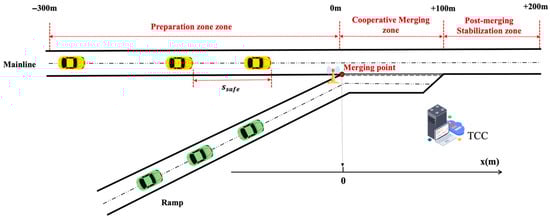
Figure 1.
Schematic diagram of the confluence area.
In the proposed cloud control architecture, a traffic control center (TCC) located at the entrance of the merging area collects real-time vehicle state information through Vehicle-to-Infrastructure (V2I) communication. The TCC processes this information to generate optimal trajectories for all vehicles within the control zone, which spans from 300 m upstream of the merging point to 100 m downstream. For clarity, the control zone is explicitly divided into three functional subzones, as illustrated in Figure 1: (1) the Preparation Zone (−300 m to 0 m), where vehicles establish communication with the TCC and prepare for cooperative control; (2) the Cooperative Merging Zone (0 m to +100 m), where active trajectory adjustments and merging maneuvers occur; and (3) the Post-merging Stabilization Zone (+100 m to +200 m), where vehicles stabilize their speeds and prepare to exit the control system. The distances are now shown directly in the figure to ensure consistency with the text, and the overall control zone is explicitly indicated.
To focus on the core merging control problem while maintaining model tractability, we make the following assumptions: (1) All vehicles are CAVs equipped with identical communication and control capabilities, ensuring perfect execution of TCC commands. (2) Only longitudinal control is considered, with lateral movements restricted to the merging maneuver itself. (3) The merging point is clearly defined where the acceleration lane ends and vehicles must have completed their merging maneuver.
3.2. Mathematical Formulation
3.2.1. Objective Function
The cooperative merging control problem is formulated as a mixed-integer linear programming (MILP) model that optimizes vehicle trajectories while ensuring safety and operational constraints. Let and denote the sets of vehicles on the mainline and ramp, respectively, with representing all vehicles in the control zone. The planning horizon is discretized into time steps with interval s.
For each vehicle at time , we define the following continuous variables: position , velocity , and acceleration . Additionally, binary variables indicate the relative order of vehicles and at the merging point, where if vehicle passes the merging point before vehicle , and 0 otherwise.
The objective function minimizes a weighted combination of travel time, acceleration variations, and velocity deviations from desired speeds, with an additional penalty term for slack variables associated with the ramp acceleration requirement:
where represents the desired velocity (20 m/s for mainline vehicles, 12 m/s for ramp vehicles), and , , are weighting coefficients set to 1.0, 0.5, and 0.3, respectively, based on preliminary sensitivity analysis.
3.2.2. Model Constraints
The model incorporates several categories of constraints to ensure realistic and safe vehicle behavior:
Vehicle Dynamics Constraints: These constraints govern the fundamental motion of vehicles according to kinematic laws:
where /s ensures vehicles maintain minimum speed for safety, and the acceleration limits prevent uncomfortable or unsafe maneuvers.
Safety Distance Constraints: To prevent collisions, vehicles must maintain safe following distances based on their speeds and relative positions. For vehicles on the same lane, let denote the set of vehicles in lane , where represents the mainline and ramp lanes, respectively. Within each lane , vehicles are indexed such that indicates that vehicle is ahead of vehicle in the traffic flow direction. For vehicles on the same lane:
where represents the minimum standstill distance, and s is the safe time headway. The constraint ensures that faster-following vehicles maintain larger gaps.
Merging Sequence Constraints: These constraints establish a consistent merging order throughout the control horizon. Once the relative order of two vehicles is determined, it must be maintained:
Merging Feasibility Constraints: At the merging point, vehicles from different lanes must respect the established merging sequence while maintaining safe distances:
where is a sufficiently large constant, ensures adequate spacing during merging, and represents time steps when vehicles are near the merging point.
Ramp Vehicle Acceleration Constraints: To model realistic merging behavior, ramp vehicles can accelerate when approaching the merging point:
To ensure safety always takes precedence, the ramp acceleration requirement is modeled as a soft constraint with a slack variable . A penalty term is added to the objective function, so that safety constraints remain strict hard constraints, while the acceleration condition serves only as a supportive mechanism for smoother merging.
4. Delay Compensation Model for Cloud-Based Control System
4.1. Communication Delay Modeling
To complete the DCMC framework, this section presents a comprehensive delay compensation mechanism that addresses the inherent communication delays between vehicles and the TCC. These delays, if unaccounted for, can significantly degrade control performance and compromise safety. By integrating this mechanism with the trajectory optimization model introduced in Section 3, the proposed approach ensures robust and reliable cooperative merging under realistic cloud-based communication conditions.
In cloud-based vehicular control systems, the total communication delay consists of three primary components:
where represents the uplink transmission delay from vehicles to the TCC, denotes the computational processing time at the TCC, and is the downlink transmission delay from the TCC to vehicles.
Recent field measurements and simulation studies have shown that vehicular communication delays typically follow Gaussian distributions under stable network conditions. Based on this observation, we model the total delay as:
where represents the mean total delay, and is the standard deviation, assuming independent uplink and downlink delays.
For the proposed system, we consider typical 5G-V2X communication parameters with = = 30 ms and = = 15. The computational delay is treated as deterministic and can be adjusted to ensure that the total mean delay satisfies , resulting in .
4.2. Predictive Compensation for Deterministic Delay
The deterministic component of communication delay (mean delay ) causes a systematic time lag between state measurement and control execution. Without compensation, the TCC would base its trajectory planning on outdated vehicle states, leading to suboptimal or potentially unsafe control decisions, as shown in Figure 2.
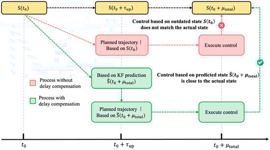
Figure 2.
Predictive Delay Compensation Strategy Diagram.
To address this challenge, we employ a Kalman filter-based state prediction approach that estimates vehicle states at the future time when control commands will be executed. The vehicle motion model is represented in discrete state-space form:
where the state vector contains position, velocity, and acceleration.
The state transition matrix incorporates a control availability indicator that differs from the merging sequence variable. To avoid confusion, we clarify that in the matrix , the term replaces the previously shown notation, where represents the control availability factor:
Thus, the corrected state transition matrix becomes:
The Kalman filter implementation requires specification of the noise characteristics and observation model. The process noise covariance matrix accounts for model uncertainties:
The measurement noise covariance matrix reflects sensor accuracy:
The observation matrix assumes full state observability:
where represents the measurement vector containing observed position, velocity, and acceleration. The Kalman filter operates through recursive prediction and update steps:
Prediction Step:
Update Step:
where and represent process and measurement noise covariance matrices, respectively, and is the observation matrix.
It is worth noting that in this study we employed the standard Kalman filter rather than more advanced variants such as the Extended Kalman Filter (EKF) or particle filter. This choice was made because the vehicle motion dynamics are modeled in a linear form and the compensation only requires short-term state prediction of position, velocity, and acceleration. Under these conditions, the standard Kalman filter provides adequate estimation accuracy with minimal computational burden (less than 0.05 s per cycle), which is essential for real-time implementation. While EKF or particle filters could potentially improve estimation in highly nonlinear or more uncertain systems, they also introduce additional computational complexity and may reduce real-time responsiveness. Future work may explore these advanced approaches if more complex dynamics or uncertainty models are incorporated.
4.3. Trajectory Correction for Stochastic Delays
While the Kalman filter effectively compensates for mean delays, the stochastic component of communication delay introduces random variations that can cause vehicles to deviate from their planned trajectories. To address this challenge, we propose a two-stage trajectory correction mechanism that actively compensates for position and velocity errors.
4.3.1. Impact Analysis of Stochastic Delays
Stochastic delay variations manifest in two primary scenarios: Early arrival (): Control commands arrive before the predicted time, causing premature trajectory execution; Late arrival (): Control commands arrive after the predicted time, resulting in delayed trajectory execution. Both scenarios lead to deviations between the actual vehicle state and the planned trajectory. To ensure safety with high confidence (99.7%), we design for the worst-case delay deviation:
where is the confidence factor (typically for 99.7% confidence), During the delay deviation period, assuming the vehicle maintains approximately constant velocity or acceleration.
4.3.2. Two-Stage Correction Strategy
To simultaneously compensate for position and velocity errors within a finite correction period , we propose a two-stage correction mechanism. The correction time is divided into two equal stages of duration , with different correction accelerations and applied in each stage, as shown in Figure 3. The correction process begins from the vehicle’s current nominal trajectory state at correction initiation: (position), (velocity), and (acceleration).
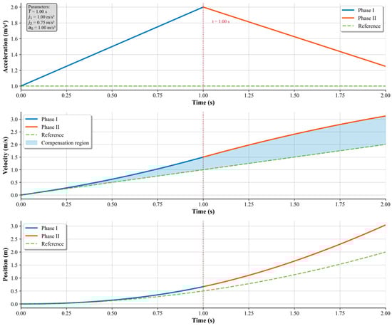
Figure 3.
Kinematic Plots of the Two-Stage Trajectory Correction.
Phase 1: Acceleration Phase (). During the first phase, the vehicle applies an additional positive correction acceleration superimposed on its nominal acceleration :
Phase 2: Deceleration Phase (). In the second phase, a negative correction acceleration is applied to regulate the velocity while continuing position correction:
To quantify the correction effect, we compare the corrected trajectory with the nominal trajectory (without correction). The position compensation achieved through the two-stage process is:
Similarly, the velocity compensation is:
The required correction accelerations to compensate for errors and are:
Solving the system of Equations (25)–(27) yields:
These formulas enable direct calculation of the correction accelerations needed to compensate for any given position and velocity errors within the correction period .
4.4. Operational Limit Adjustment
During trajectory planning, the following reduced limits ensure correction capability:
Velocity Limits:
Acceleration Limits:
The required margins are determined by the maximum correction accelerations:
These safety margins ensure that vehicles always retain sufficient dynamic capability to execute trajectory corrections, even under worst-case stochastic delay conditions. The two-stage correction mechanism, combined with appropriate safety margins, provides robust compensation for random communication delays while maintaining trajectory smoothness and vehicle stability.
4.5. Integrated DCMC Framework
The practical implementation of the DCMC system requires seamless integration of the trajectory optimization model (Section 3) with the delay compensation mechanisms (Section 4.1, Section 4.2, Section 4.3 and Section 4.4). This section presents how the TCC orchestrates these components to achieve robust real-time control under communication uncertainties.
4.5.1. System Architecture and Control Flow
The integrated system operates through a rolling horizon framework with synchronized control cycles, as shown in Figure 4. Each cycle follows a precise timeline: vehicles transmit their states at , which arrive at the TCC after uplink delay. During the computation phase (0.5 s to 2.5 s), the TCC first employs Kalman filtering to predict vehicle states at the future execution time , then solves the cooperative merging optimization using these predictions.
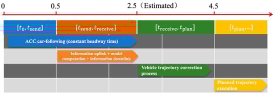
Figure 4.
Timing Diagram of the Integrated Delay Compensation Framework.
The TCC generates comprehensive control packages for each vehicle containing complete trajectory waypoints:
These control commands are transmitted back to vehicles at . Upon receiving commands, each vehicle immediately compares its actual state with the TCC’s prediction. If position or velocity errors exceed thresholds (0.01 m or 0.1 m/s), the vehicle executes a two-stage correction during [2.5 s, 4.5 s], computing accelerations and locally using Equation (28). This distributed correction mechanism enables immediate response without additional communication overhead.
This 2 s computation window accounts for worst-case communication and processing delays while maintaining responsive control. Prior to state transmission, vehicles operate under Adaptive Cruise Control (ACC) car-following mode. The rolling horizon approach ensures continuous coverage, with each new cycle beginning as the previous one concludes, maintaining trajectory continuity across planning horizons.
4.5.2. Robust Optimization Under Uncertainty
To ensure trajectory feasibility despite delay-induced deviations, the optimization framework incorporates key modifications. The optimization formulation from Section 3.2 requires modification to account for delay-induced uncertainties. The key adaptation involves replacing the original operational constraints with reduced limits that reserve dynamic capability for trajectory corrections:
where and are determined by the maximum correction accelerations required under worst-case delay scenarios, as derived in Section 4.3.
Beyond modifying operational limits, the optimization also enhances safety constraints to account for position uncertainty. The minimum following distance in Equation (6) is augmented with an uncertainty buffer:
The additional safety margin in Equation (31) accounts for the growing position uncertainty under stochastic delays. This formulation recognizes that faster-moving vehicles experience larger absolute position deviations for the same delay variation, as the uncertainty propagates proportionally to the vehicle’s speed. The theoretical basis stems from the relationship:
where represents the random delay variation. By incorporating the delay standard deviation , this term provides a probabilistic safety buffer that scales appropriately with vehicle speed, ensuring that the safety constraints remain robust under communication uncertainties.
The TCC solves this modified MILP problem during the interval , generating optimal trajectories for all vehicles over a planning horizon. The solution includes not only the desired position, velocity, and acceleration profiles but also pre-computed correction parameters for each trajectory segment.
This integrated framework successfully addresses the fundamental challenge of cloud-based control by combining predictive state estimation, conservative trajectory planning, and reactive local corrections. The hierarchical separation between strategic planning at the TCC and tactical corrections at individual vehicles leverages the strengths of both centralized coordination (global optimality) and distributed execution (rapid response), delivering reliable cooperative merging despite significant communication delays.
5. Case Study
5.1. Small-Scale Demonstration: Four-Vehicle Merging Scenario
5.1.1. Scenario Setup
To demonstrate the detailed workings of the proposed cloud-controlled cooperative merging system, we analyze a representative four-vehicle scenario consisting of two mainline vehicles and two ramp vehicles approaching a typical highway merging area. This controlled scenario allows for detailed examination of the optimization mechanisms, vehicle coordination strategies, and delay compensation processes that form the core of our approach.
The scenario configuration is illustrated in Figure 5, where vehicle M1 is positioned on the mainline and vehicle R1 on the on-ramp, both at an initial distance of 260 m from the merging point. Meanwhile, vehicle M2 is on the mainline and vehicle R2 on the on-ramp, both located 300 m upstream of the merging point. All vehicles begin with identical initial velocities of 12 m/s, creating a challenging merging scenario where coordination is essential to avoid conflicts and optimize traffic flow.
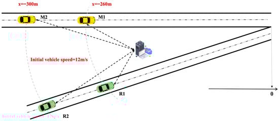
Figure 5.
Cooperative Merging Scenario Setup.
System Parameters: The cooperative control system operates with the parameters summarized in Table 1, which are selected based on realistic vehicle capabilities and communication system characteristics.

Table 1.
Parameter value.
To clarify computational feasibility, it is worth noting that the MILP problem size is naturally limited by the number of vehicles present in the merging area, ensuring manageable complexity. In our experiments, the optimization was solved using Gurobi 11.0.2 on a MacBook Pro (M3 Pro, 18 GB RAM; Apple Inc., Beijing, China). Most instances were solved within 1 s, and a maximum time limit of 2 s was imposed to guarantee that the solver always returns a feasible solution. The delay compensation module, consisting of Kalman filter-based prediction and a lightweight kinematic correction, required less than 0.05 s per control cycle. These results demonstrate that the proposed framework can be implemented in real time under current hardware conditions.
5.1.2. Communication Delay Compensation Process
The delay compensation framework is essential for maintaining system performance under realistic communication conditions. This section demonstrates how the integrated prediction-correction mechanism systematically addresses both deterministic and stochastic delay components, using Vehicle M1 as a detailed case study before examining the overall system performance.
(1) Detailed Analysis: M1 Compensation Process
M1 provides an ideal case study as it experiences moderate delay effects representative of typical system operation. Figure 6 and Figure 7 shows the complete acceleration, velocity, and position evolution throughout the compensation process.
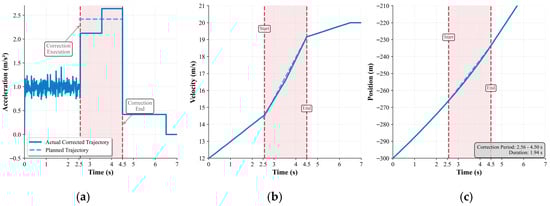
Figure 6.
Trajectory correction during delay compensation: (a) acceleration profile, (b) velocity profile, (c) position profile.
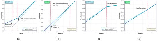
Figure 7.
Zoomed-in views of trajectory correction near the start and end moments: (a) Velocity correction at the start of execution. (b) Position correction at the start of execution. (c) Velocity correction at the end of execution. (d) Position correction at the end of execution.
Initial State Deviation: When the control command arrives at t = 2.56 s (0.06 s later than expected), M1 exhibits cumulative state errors: position lag Δx = −0.314 m and velocity deficit Δv = −0.074 m/s. These deviations result from both Kalman filter prediction uncertainty and the stochastic delay component.
Two-Stage Correction Execution: The system calculates optimal correction accelerations j1 = −0.296 m/s2 and j2 = −0.219 m/s2 to be applied over the available correction time of 1.94 s. The acceleration profile in Figure 6a clearly shows the characteristic step changes that implement this correction strategy.
Convergence Performance: Figure 6b,c demonstrate rapid convergence of both velocity and position to the planned trajectory. By t = 4.5 s, tracking errors in both position and velocity are reduced to negligible levels, confirming the effectiveness of the correction mechanism.
(2) System-Wide Compensation Results
Table 2 summarizes the compensation performance across all four vehicles, revealing consistent effectiveness despite varying initial conditions.
Table 2.
Vehicle Delay Compensation Results Summary.
The results demonstrate three key findings: (1) All vehicles achieve successful error correction within 2.1 s regardless of initial deviation magnitude. (2) Correction accelerations remain within comfortable limits 2), ensuring passenger comfort. (3) The framework adapts effectively to both positive and negative errors, as shown by R2′s positive correction accelerations.
5.1.3. Cooperative Merging Behavior Analysis
To evaluate the impact of communication delays on merging performance, this section compares two scenarios: ideal no-delay conditions versus the proposed delay-compensated cooperative control operating under realistic communication constraints ().
Velocity Profile Impact. Figure 8 shows the comparative velocity evolution for all vehicles. Under delay-compensated conditions, vehicles exhibit delayed responses due to the 2 s mean communication delay, with coordination patterns offset by approximately 2 s compared to the ideal case. The reserved safety margins constrain vehicle acceleration capabilities, resulting in more gradual speed transitions. Despite these limitations, successful speed harmonization is achieved with final speed differentials below 2 m/s at the merging point.
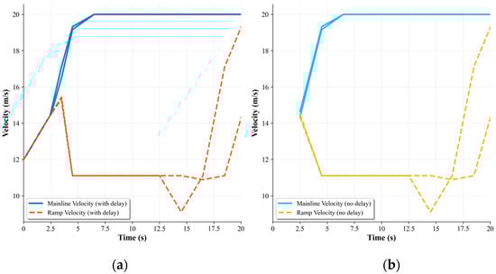
Figure 8.
Merging Speed Profile Comparison. (a) With delay. (b) No delay.
Merging Timeline Comparison. Figure 9 illustrates the position trajectories, revealing that the no-delay scenario completes merging at t = 21 s while the delay-compensated case requires t = 21.8 s and a 3.8% increase in completion time. However, the delay-compensated trajectories demonstrate greater smoothness and maintain larger safety margins.
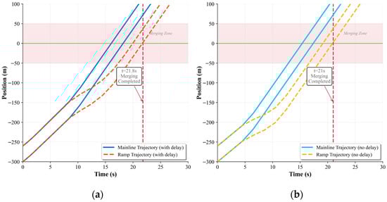
Figure 9.
Merging Trajectory Comparison. (a) With delay. (b) No delay.
The analysis reveals a well-balanced trade-off wherein the delay compensation framework achieves 96.2% of theoretical throughput performance while sacrificing 3.8% of ideal efficiency to accommodate realistic communication conditions. The reserved dynamic margins effectively eliminate collision risks while maintaining system stability under stochastic delay variations. The results validate the framework’s effectiveness in maintaining both safety requirements and operational efficiency within practical deployment constraints.
5.2. Large-Scale Performance Evaluation
5.2.1. Safety Comparison with Delay-Aware Strategies
In this section, we compare the proposed DCMC framework with three representative delay-aware cooperative merging strategies: No Compensation, where communication delay is ignored; Prediction-Only, which mitigates average delay via state prediction; and Robust control, inspired by the delay-tolerant control design approach [], which treats communication delay as a bounded uncertainty and enforces conservative safety margins to ensure robustness. These methods collectively represent the main practical approaches to handling communication delays in cooperative merging control.
The boxplots in Figure 10 compare the minimum TTC distributions across the four strategies under different traffic flow levels. As expected, higher traffic demand consistently reduces overall TTC values, reflecting increased conflict intensity in dense merging environments. While the differences among strategies are relatively small under low demand, the gaps expand markedly as traffic approaches capacity. The No Compensation strategy exhibits the poorest performance, with heavy left tails and high violation rates that grow dramatically with flow level. Prediction-Only improves the distributions by mitigating deterministic delays, but stochastic fluctuations still generate a considerable share of unsafe events. Robust control successfully suppresses most violations, yet it does so by enlarging safety margins, leading to overly conservative spacing and reduced throughput. In contrast, the proposed DCMC framework achieves the most balanced outcome across all demand levels. It not only prevents the emergence of extremely low TTC values more effectively than Prediction-Only, but also attains violation rates that are comparable to or even lower than those of Robust control. At the same time, its median TTC values remain slightly lower than Robust control, indicating reduced conservatism and higher efficiency. Taken together, these results demonstrate that DCMC consistently provides the best trade-off between safety and efficiency, ensuring robust protection against communication delays while sustaining practical merging performance across varying traffic densities.
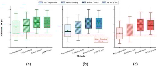
Figure 10.
Boxplots of minimum TTC distributions. (a) Low. (b) Medium. (c) High.
5.2.2. Efficiency Evaluation Under Large-Scale Scenarios
To comprehensively evaluate the system’s performance under diverse traffic conditions, we conducted large-scale simulations comparing the cooperative control method against a base case where no centralized coordination is applied. The evaluation encompasses three traffic density levels: low (800 vehicles per hour [vph]: 600 mainline, 200 ramp), medium (1600 vph: 1200 mainline, 400 ramp), and high (2200 vph: 1600 mainline, 600 ramp), with the latter approaching theoretical single-lane capacity. In the base case, vehicles exhibit typical highway driving behavior using the ACC for car-following and conventional gap-acceptance logic for merging. The cooperative control utilized balanced weighting ( = 1.0, = 0.5, = 0.3) with realistic communication delays of .
To visualize the simulated traffic conditions, we recorded the speed and position of each vehicle within the control zone (400 m upstream to 100 m downstream of the merging point) at each 0.1 s timestep. Figure 11 presents the vehicle trajectories, where black solid lines indicate mainline vehicles and red dashed lines represent ramp vehicles. These trajectory plots reveal traffic flow patterns, merging coordination phenomena, and disturbance propagation characteristics under different control strategies and density levels. Figure 12 displays speed heatmaps generated by collecting cross-sectional vehicle speeds at 50 m intervals throughout the simulation period. These contour plots visualize the spatiotemporal distribution of speeds, revealing congestion formation, shockwave propagation, and the effectiveness of speed harmonization strategies. The color gradient ranges from red (low speeds below 10 m/s) through yellow (medium speeds 12–16 m/s) to green (high speeds above 18 m/s). Table 3 and Table 4 present the quantitative performance metrics for travel time and delay, respectively, including total average values, mainline-specific, and ramp-specific measurements for each scenario. The tables also show the percentage improvement achieved by cooperative control compared to the base case. Figure 13 visualizes these improvements across traffic densities, clearly illustrating how benefits scale with congestion levels.
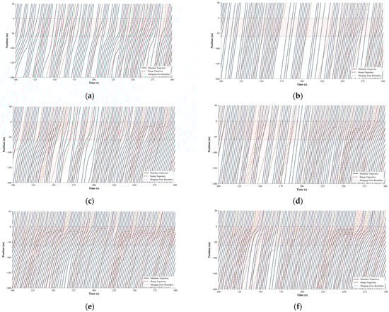
Figure 11.
Vehicle trajectories under different traffic densities. (a) Low volume of base, (b) low volume of DCMC, (c) medium volume of base, (d) medium volume of DCMC, (e) high volume of base, and (f) high volume of DCMC.
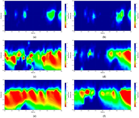
Figure 12.
Speed heatmaps under different traffic densities. (a) Low volume of base, (b) low volume of DCMC, (c) medium volume of base, (d) medium volume of DCMC, (e) high volume of base, and (f) high volume of DCMC.
Table 3.
Travel Time Performance Comparison under Different Traffic Densities.
Table 4.
Delay Performance Comparison under Different Traffic Densities.
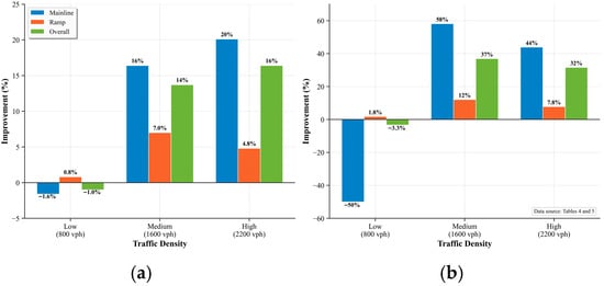
Figure 13.
Traffic Performance Improvement. (a) Travel Time Improvement. (b) Delay Improvement.
Under low traffic volumes, disturbances induced by merging vehicles are quickly absorbed in both control strategies. The trajectory plots show smooth, nearly parallel lines with only minor adjustments near the merging point, while speed heatmaps display uniform high-speed green zones throughout. This visual stability translates to virtually identical travel times (24.4 s vs. 24.6 s) and minimal delays (4.5 s vs. 4.7 s). The marginal performance differences (−1.0% travel time, −3.3% delay) reflect the overhead of proactive coordination in uncongested conditions when natural gaps are abundant.
As traffic density increases to medium levels, critical coordination phenomena emerge that differentiate the two approaches. In the base case, disturbances from merging vehicles begin accumulating, creating visible trajectory compressions that propagate upstream. Multiple ramp vehicles struggle to find adequate gaps, their trajectories flattening as they experience forced decelerations and near-stops at the acceleration lane’s end. These microscopic conflicts manifest in the speed heatmaps as intermittent yellow-orange zones (12–14 m/s) that form and dissipate—early indicators of flow instability. Travel times increase to 32.1 s with delays reaching 11.8 s overall.
The cooperative control counters this degradation through three distinct coordination mechanisms visible in the trajectories: (1) formation of merging platoons where ramp vehicles are grouped for efficient insertion, (2) proactive speed adjustments by mainline vehicles creating precise, timed gaps, and (3) controlled dissipation of disturbances that prevents upstream propagation. The speed heatmaps confirm this stabilization, showing smooth gradients without congestion cores. These coordinated behaviors yield a 13.7% improvement in travel time and an even more impressive 36.9% reduction in delays. The delay reduction is particularly pronounced for mainline traffic (58.1%, from 8.6 s to 3.6 s), demonstrating the system’s effectiveness in protecting arterial flow from merging-induced disruptions.
Under high traffic volumes, the contrast becomes dramatic across all visualizations. The base case experiences complete traffic breakdown—accumulated disturbances trigger persistent congestion that spreads far upstream beyond the control zone. Vehicle trajectories converge into dense clusters of near-horizontal lines, the unmistakable signature of stop-and-go conditions. The speed heatmap reveals extensive red zones (<10 m/s) with visible shockwave patterns propagating upstream. This catastrophic failure inflates travel times to 40.9 s and delays to 20.6 s, while reducing effective capacity from 2200 to approximately 1850 vph.
Despite operating near theoretical capacity limits, the cooperative control maintains remarkable stability through periodic coordination cycles that collect and accommodate disturbances before they cascade into breakdown. The trajectories remain smooth and evenly spaced, while the speed heatmap shows controlled harmonization—yellow zones represent deliberate speed management rather than congestion. This visual evidence of prevented breakdown translates to substantial quantitative gains: 34.2 s travel time (16.4% improvement) and 14.1 s delay (31.6% reduction). The system sustains throughput near 2150 vph, effectively increasing operational capacity by 16.2%. The asymmetric distribution of benefits reveals the underlying coordination strategy. Mainline traffic sees disproportionate improvements in both travel time (20.1%) and delay (43.9%) at high density because the system protects arterial flow from merging-induced shockwaves. Ramp vehicles, while experiencing smaller percentage gains (4.8% travel time, 7.8% delay), benefit from guaranteed merging opportunities rather than the uncertain gap-searching that causes excessive delays in conventional operations. Figure 13 illustrates how these performance improvements scale across traffic densities, with both travel time and delay reductions becoming more pronounced as congestion levels increase.
Based on these findings, we recommend implementing the cooperative control system with traffic-responsive activation thresholds. The system should remain inactive under low-density conditions (below 1200 vph total) where natural gap-acceptance suffices. As demand approaches medium levels (1200–1800 vph), the system should activate with moderate coordination parameters. Under high-demand conditions (above 1800 vph), full coordination should engage to prevent congestion formation.
The results demonstrate that cloud-controlled cooperative merging effectively addresses the fundamental limitations of conventional highway operations, with benefits most pronounced precisely when needed—during high-demand periods approaching capacity limits. The system’s ability to prevent congestion formation while accommodating realistic communication delays validates its potential for practical deployment at critical highway bottlenecks.
6. Conclusions
6.1. Research Conclusions
This research has developed and validated a comprehensive cloud-based cooperative merging control system that addresses the critical gap between theoretical optimization and practical implementation under realistic communication constraints. The proposed Delay-Compensated Merging Control (DCMC) framework makes several key contributions to the field of connected and automated vehicle technologies.
First, the integrated approach combining trajectory optimization with delay compensation demonstrates that cloud-based control can achieve near-optimal performance despite significant communication latencies. The two-stage correction mechanism effectively handles both deterministic and stochastic delay components, maintaining trajectory tracking errors below 0.1 m in position and 0.1 m/s in velocity within 2 s of correction initiation.
Second, the performance evaluation reveals that benefits scale dramatically with traffic density, precisely when coordination is most needed. Under high-density conditions approaching theoretical capacity, the system prevents the traffic breakdown that typically occurs in conventional operations, sustaining throughput near 2150 vehicles per hour compared to the degraded 1850 vph in the base case. The 31.6% reduction in delays and 16.4% improvement in travel times at high density validate the system’s effectiveness in addressing highway bottlenecks.
Third, the framework’s design principles—including reserved dynamic margins, robust safety constraints, and hierarchical control architecture—provide a practical blueprint for real-world deployment. The system’s ability to maintain safety and efficiency with 2 s mean delays and realistic communication uncertainties addresses a critical barrier that has limited the deployment of cooperative vehicle technologies.
The research also identifies important considerations for implementation. The negligible benefits under low-density conditions suggest traffic-responsive activation strategies, where the system engages only when coordination provides meaningful improvements. The asymmetric distribution of benefits, with mainline traffic receiving greater improvements, reflects the system’s prioritization of arterial flow protection—a key design choice for highway operations.
6.2. Future Work
Although this study has demonstrated the feasibility and effectiveness of the proposed delay-compensated cooperative merging control framework, several promising research directions remain:
- (1)
- Mixed traffic and CAV penetration rates. The current study assumes a fully CAV environment to establish a clear baseline. Future work should investigate scenarios with partial CAV penetration, incorporating stochastic human driving behaviors, heterogeneous reaction times, and hybrid coordination strategies. This extension is essential for assessing system robustness under realistic adoption conditions.
- (2)
- Practical implementation challenges. Large-scale deployment will require addressing regulatory and infrastructural barriers, including communication standardization, integration with existing traffic management systems, and infrastructure investment. Extending the framework to more complex traffic environments—such as multilane highways, urban merging areas, and integration with platooning—will also be necessary. Field trials and pilot studies will provide critical validation of system performance under real-world conditions.
- (3)
- Broader considerations and cross-domain applications. Beyond technical improvements, safeguarding data privacy, cybersecurity, and ethical fairness will be indispensable for public acceptance. Furthermore, the principles of delay-compensated cooperative control could inspire applications in other autonomous systems where communication latency is critical, such as coordinated operations of maritime autonomous vehicles or aerial drone swarms.
Author Contributions
Conceptualization, H.Y. and J.W.; methodology, H.Y. and J.W.; software, C.Z.; validation, H.Y., W.L. and J.W.; formal analysis, H.Y. and C.Z.; investigation, W.L. and C.Z.; resources, J.W.; data curation, C.Z.; writing—original draft preparation, H.Y.; writing—review and editing, H.Y., W.L. and J.W.; visualization, C.Z.; supervision, J.W.; project administration, J.W.; funding acquisition, J.W. All authors have read and agreed to the published version of the manuscript.
Funding
This research is supported by the Project of Hebei Province Innovation Capacity Enhancement Plan (244X0801D).
Institutional Review Board Statement
Not applicable.
Informed Consent Statement
Not applicable.
Data Availability Statement
Data will be available on request.
Acknowledgments
The authors thank Beijing Jiaotong University and the Transport Planning and Research Institute, Ministry of Transport, for providing research facilities and technical support during this study. This work was supported by the National Natural Science Foundation of China (Grant No. 62173167).
Conflicts of Interest
Author Wei Li was employed by the company China Road and Bridge Corporation. The remaining authors declare that the research was conducted in the absence of any commercial or financial relationships that could be construed as a potential conflict of interest.
References
- Zhang, K.; Batterman, S. Air Pollution and Health Risks Due to Vehicle Traffic. Sci. Total Environ. 2013, 450, 307–316. [Google Scholar] [CrossRef]
- Barth, M.; Boriboonsomsin, K. Real-World Carbon Dioxide Impacts of Traffic Congestion. Transp. Res. Rec. 2010, 2058, 163–171. [Google Scholar] [CrossRef]
- Cassidy, M.J.; Bertini, R.L. Some Traffic Features at Freeway Bottlenecks. Transp. Res. Part B Methodol. 1999, 33, 25–42. [Google Scholar] [CrossRef]
- Daganzo, C.F. The Cell Transmission Model: A Dynamic Representation of Highway Traffic Consistent with the Hydrodynamic Theory. Transp. Res. Part B Methodol. 1994, 28, 269–287. [Google Scholar] [CrossRef]
- Papageorgiou, M.; Hadj-Salem, H.; Blosseville, J. ALINEA: A Local Feedback Control Law For on-Ramp Metering. Transp. Res. Rec. 1990, 1320, 58–67. [Google Scholar]
- Chen, D.; Ahn, S.; Hegyi, A. Variable Speed Limit Control for Steady and Oscillatory Queues at Fixed Freeway Bottlenecks. Transp. Res. B Methodol. 2014, 70, 340–358. [Google Scholar] [CrossRef]
- Shladover, S.; Su, D.; Lu, X.-Y. Impacts of Cooperative Adaptive Cruise Control on Freeway Traffic Flow. Transp. Res. Rec. 2012, 2324, 63–70. [Google Scholar] [CrossRef]
- Talebpour, A.; Mahmassani, H.S. Influence of Connected and Autonomous Vehicles on Traffic Flow Stability and Throughput. Transp. Res. C Emerg. Technol. 2016, 71, 143–163. [Google Scholar] [CrossRef]
- Feng, Y.; Head, K.L.; Khoshmagham, S.; Zamanipour, M. A Real-Time Adaptive Signal Control in a Connected Vehicle Environment. Transp. Res. C Emerg. Technol. 2015, 55, 460–473. [Google Scholar] [CrossRef]
- Rios-Torres, J.; Malikopoulos, A.A. Automated and Cooperative Vehicle Merging at Highway On-Ramps. IEEE Trans. Intell. Transp. Syst. 2017, 18, 780–789. [Google Scholar] [CrossRef]
- Ntousakis, I.A.; Nikolos, I.K.; Papageorgiou, M. Optimal Vehicle Trajectory Planning in the Context of Cooperative Merging on Highways. Transp. Res. C Emerg. Technol. 2016, 71, 464–488. [Google Scholar] [CrossRef]
- Zhou, Y.; Cholette, M.E.; Bhaskar, A.; Chung, E. Optimal Vehicle Trajectory Planning With Control Constraints and Recursive Implementation for Automated On-Ramp Merging. IEEE Trans. Intell. Transp. Syst. 2019, 20, 3409–3420. [Google Scholar] [CrossRef]
- Letter, C.; Elefteriadou, L. Efficient Control of Fully Automated Connected Vehicles at Freeway Merge Segments. Transp. Res. C Emerg. Technol. 2017, 80, 190–205. [Google Scholar] [CrossRef]
- Wang, Z.; Wu, G.; Barth, M.J. A Review on Cooperative Adaptive Cruise Control (CACC) Systems: Architectures, Controls, and Applications. In Proceedings of the 2018 21st International Conference on Intelligent Transportation Systems (ITSC), Maui, HI, USA, 4–7 November 2018; pp. 2884–2891. [Google Scholar]
- Milanés, V.; Shladover, S.E. Modeling Cooperative and Autonomous Adaptive Cruise Control Dynamic Responses Using Experimental Data. Transp. Res. Part C Emerg. Technol. 2014, 48, 285–300. [Google Scholar] [CrossRef]
- Kotsialos, A.; Papageorgiou, M. Efficiency and Equity Properties of Freeway Network-Wide Ramp Metering with AMOC. Transp. Res. Part C Emerg. Technol. 2004, 12, 401–420. [Google Scholar] [CrossRef]
- Hegyi, A.; De Schutter, B.; Hellendoorn, H. Model Predictive Control for Optimal Coordination of Ramp Metering and Variable Speed Limits. Transp. Res. C Emerg. Technol. 2005, 13, 185–209. [Google Scholar] [CrossRef]
- Abdel-Aty, M.; Cunningham, R.J.; Gayah, V.V.; Hsia, L. Dynamic Variable Speed Limit Strategies for Real-Time Crash Risk Reduction on Freeways. Transp. Res. Rec. 2008, 2078, 108–116. [Google Scholar] [CrossRef]
- Yu, R.; Abdel-Aty, M. Utilizing Support Vector Machine in Real-Time Crash Risk Evaluation. Accid. Anal. Prev. 2013, 51, 252–259. [Google Scholar] [CrossRef]
- Swaroop, D.; Hedrick, J.K. String Stability of Interconnected Systems. IEEE Trans. Autom. Control 1996, 41, 349–357. [Google Scholar] [CrossRef]
- Varaiya, P. Smart Cars on Smart Roads: Problems of Control. IEEE Trans. Autom. Control 1993, 38, 195–207. [Google Scholar] [CrossRef]
- Milanes, V.; Godoy, J.; Villagra, J.; Perez, J. Automated On-Ramp Merging System for Congested Traffic Situations. IEEE Trans. Intell. Transp. Syst. 2011, 12, 500–508. [Google Scholar] [CrossRef]
- Wang, Y.; Cai, P.; Lu, G. Cooperative Autonomous Traffic Organization Method for Connected Automated Vehicles in Multi-Intersection Road Networks. Transp. Res. C Emerg. Technol. 2020, 111, 458–476. [Google Scholar] [CrossRef]
- Marinescu, D.; Čurn, J.; Bouroche, M.; Cahill, V. On-Ramp Traffic Merging Using Cooperative Intelligent Vehicles: A Slot-Based Approach. In Proceedings of the 2012 15th International IEEE Conference on Intelligent Transportation Systems, Anchorage, AK, USA, 16–19 September 2012; pp. 900–906. [Google Scholar]
- Zhou, M.; Qu, X.; Jin, S. On the Impact of Cooperative Autonomous Vehicles in Improving Freeway Merging: A Modified Intelligent Driver Model-Based Approach. IEEE Trans. Intell. Transp. Syst. 2017, 18, 1422–1428. [Google Scholar] [CrossRef]
- Xu, B.; Li, S.E.; Bian, Y.; Li, S.; Ban, X.J.; Wang, J.; Li, K. Distributed Conflict-Free Cooperation for Multiple Connected Vehicles at Unsignalized Intersections. Transp. Res. C Emerg. Technol. 2018, 93, 322–334. [Google Scholar] [CrossRef]
- Kenney, J.B. Dedicated Short-Range Communications (DSRC) Standards in the United States. Proc. IEEE 2011, 99, 1162–1182. [Google Scholar] [CrossRef]
- Sommer, C.; German, R.; Dressler, F. Bidirectionally Coupled Network and Road Traffic Simulation for Improved IVC Analysis. IEEE Trans. Mob. Comput. 2011, 10, 3–15. [Google Scholar] [CrossRef]
- Wang, J.; Shao, Y.; Ge, Y.; Yu, R. A Survey of Vehicle to Everything (V2X) Testing. Sensors 2019, 19, 334. [Google Scholar] [CrossRef] [PubMed]
- Seiler, P.; Pant, A.; Hedrick, K. Disturbance Propagation in Vehicle Strings. IEEE Trans. Autom. Control 2004, 49, 1835–1842. [Google Scholar] [CrossRef]
- Dey, K.C.; Yan, L.; Wang, X.; Wang, Y.; Shen, H.; Chowdhury, M.; Yu, L.; Qiu, C.; Soundararaj, V. A Review of Communication, Driver Characteristics, and Controls Aspects of Cooperative Adaptive Cruise Control (CACC). IEEE Trans. Intell. Transp. Syst. 2016, 17, 491–509. [Google Scholar] [CrossRef]
- Ploeg, J.; Shukla, D.P.; van de Wouw, N.; Nijmeijer, H. Controller Synthesis for String Stability of Vehicle Platoons. IEEE Trans. Intell. Transp. Syst. 2014, 15, 854–865. [Google Scholar] [CrossRef]
- Massera Filho, C.; Terra, M.H.; Wolf, D.F. Safe Optimization of Highway Traffic With Robust Model Predictive Control-Based Cooperative Adaptive Cruise Control. IEEE Trans. Intell. Transp. Syst. 2017, 18, 3193–3203. [Google Scholar] [CrossRef]
Disclaimer/Publisher’s Note: The statements, opinions and data contained in all publications are solely those of the individual author(s) and contributor(s) and not of MDPI and/or the editor(s). MDPI and/or the editor(s) disclaim responsibility for any injury to people or property resulting from any ideas, methods, instructions or products referred to in the content. |
© 2025 by the authors. Licensee MDPI, Basel, Switzerland. This article is an open access article distributed under the terms and conditions of the Creative Commons Attribution (CC BY) license (https://creativecommons.org/licenses/by/4.0/).