Abstract
The advancement of using the cryogenic energy storage (CES) system has enabled efficient utilization of abandoned wind and solar energy, and the system can be dispatched in the peak hours of regional power load demand to release energy. It can fill the demand gap, which is conducive to the peak regulation of the power system and can further promote the rapid development of new energy. This study optimizes the various types of energy complementary to the CES system using hybrid gravitational search algorithm-local search optimization (hGSA-LS). First, the mathematical model of the energy storage system (ESS) including the CES system is briefly described. Second, an economic scheduling optimization model of the IES is constructed by minimizing the operating cost of the system. Third, the hGSA-LS methods to solve the optimization problem are proposed. Simulations show that the hGSA-LS methodology is more efficient. The simulation results verify the feasibility of CES compared with traditional systems in terms of economic benefits, new energy consumption rate, primary energy saving rate, and carbon emissions under different fluctuations in energy prices. Optimization of the system operation using the proposed hGSA-LS algorithm takes 5.87 s; however, the GA, PSO, and GSA require 12.56, 10.33, and 7.95 s, respectively. Thus, the hGSA-LS algorithm shows a comparatively better performance than GA, PSO, and GSA in terms of time.
1. Introduction
The uncertainties of renewable energy sources (RESs), such as wind, solar, and tidal energy, contribute to the complementary benefits of energy storage systems (ESSs) [1]. The reliability of the energy supply improves through the integrated energy system (IES), and it enhances the performance of RES as flexible resources [2]. The strategic decision to achieve carbon peak and neutrality is based on national conditions of large carbon emissions and high energy demand in the energy system [2,3]. Research on IES has become the focus of attention of relevant researchers from the perspective of the power market, and the economic benefit of energy storage for IES has become the key to future energy generation [4]. In [5], the wind power consumption strategy based on the cryogenic energy storage (CES) system is proposed according to the characteristics of strong wind power fluctuation. The feasibility of the application of wind-assisted energy storage equipment in wind farms is also verified. In [6], a basis for the strategy of the operation of the air storage system is provided from the perspective of the variable operational conditions of the compressor. In [7], the frequency modulation capability of air-liquid energy storage is verified to meet the requirements of the power grid with a combined compressed air system. The optimization scheduling model of the combined operation system of the air storage system is also established. In [8,9], a scheme for the combined operation of compressed air energy storage and absorption chiller is proposed to improve the energy storage efficiency. The influence of system parameters on the combined operation is studied as well. In [10,11], the microgrid based on the combined heating and power (CHP) unit, refrigerating machine, and compressed air systems is explored from the perspective of improving energy efficiency by optimizing system parameters.
Recently, the computational algorithm, such as combining the GSA algorithm with different approaches to create hybrid algorithms, such as hGA-GSA and hPSO-GSA, is an effective strategy to improve the GSA algorithm [9]. The constants used to harmonize GSA should be regulated appropriately due to the lack of the exploration principle [10]. The influence of fitness function on mass grows stronger during the GSA process, which causes the masses to grow increasingly heavier. As a result, the masses congregate in a nearby area, which neutralizes gravitational forces and prevents them from being exploited to their full potential [12]. Therefore, IES optimization and the influence of the CES system can improve energy storage efficiency from the perspective of thermodynamics. However, there are not many explorations on the optimization scheduling modeling and operation of energy consumption and joint supply of multiple types of energy from the perspective of economic benefits [12].
This study proposes an IES that considers the characteristics of multi-energy cogeneration and new energy absorption of the CES system. The IES dispatching control center manages the CHP unit, CES unit, electric refrigerator, and other equipment in the system in a unified manner, to minimize the overall operation cost. An optimization scheduling model is established, and an environmental performance index is introduced to minimize IES operating costs. The proposed method is verified with the help of the MATLAB platform by using the actual load data of an industrial park located in Pakistan. The simulation verification of the feasibility of this green growth system operation ensures that the system can operate in an optimal economic model and consider the absorption benefits of RES, such as wind power generation.
2. Background Study
2.1. Description of IES
The IES is composed of a compressor, gas storage chamber, heat exchange/cooler, heat storage/cooler, and other main components [13]. A complex coupling relationship exists among internal airflow, pressure, heat storage power generation, and other variable constraints, such as pressure change rate constraints. The heat exchange, power constraint, operating condition, power constraint, and air storage chamber pressure constraint should be satisfied during scheduling operation [14,15]. The IES is a system formed by strengthening the optimization of the coupling relationship among the production, storage, and dispatching of various kinds of energy to meet the demands of various types of energy on the load side. The structure realizes the connection of cold, heat, electricity, and natural gas networks through different equipment, which utilizes the advantages of the CES system connection and utilization of multiple energy sources, as shown in Figure 1. Therefore, after the CES system is connected to IES, the flow of all kinds of energy is strengthened, the absorption of new energy is increased, and it is used to supply a variety of energy flow loads in a corresponding time [16]. The absorption capacity of wind power generation and solar power generation is studied in [17]. In the traditional cogeneration system, the conversion relationship between electric energy and other energy sources is only adjusted by conventional units, such as thermal power.
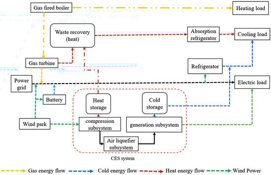
Figure 1.
IES structure including CES system.
The CES is an energy storage method that converts electric energy into the internal energy of liquid air and stores it [18]. The CES is safe, reliable, and low cost, and it has a long service life; thus, it is more suitable for IES due to multi-type prominent characteristics of energy supply [15]. The operation of the CES ESS mainly includes two stages: energy storage and energy release. In ESS, the abandoned wind power is used to drive the air compressor to compress the air at a high temperature and pressure [19]. After the heat exchange by step compression, the compression heat is stored in the heat storage tank, and the air finally enters the liquefaction system.
When the air compressor and turbine expander store the energy, the compression power of the air compressor can be defined as:
where , are the energy consumption of the air compressor and the output power of the turbine expander within a unit period; min, max corresponds to the maximum and minimum output power of the air compressor and turbine expander, respectively; and are the air mass flow into the air compressor and turbine expander; , is the inlet temperature of the air compressor and turbine expander; is the gas constant of air, 287 J/(kg·k); ηc and ηg are the entropic efficiency of air compressor and turbine expansion; ηc,m, ηg,m are the conversion efficiency of the motor to the air compressor and the turbine expander to the motor; β is the compression ratio; γ is the expansion ratio; α is an adiabatic number, take 0.68; and nc and ng are the series of the air compressor and turbine.
The liquid air is stored in the tank at atmospheric pressure, compared with a high-pressure gas storage tank, safety is expressed as follows:
where is the volume change of liquefied air in a liquid air storage tank in the unit period; ρ air is the density of liquid air, 0.9 kg/m3; and is the initial volume of liquefied air in the liquid-air storage tank.
The heat in the storage tank during the operation of the cryogenic liquefaction system is:
where is the heat of compression; is the heating power of the system; and are the storage and heat release efficiency of the cryogenic liquefaction system.
The cold quantity in the storage tank during the operation of the cryogenic liquefaction system is:
where is the cooling quantity value in a unit period; is the isobaric specific heat capacity of air; is the inlet temperature of the last stage turbine expander; γ is the last stage of the turbine expander series; and is the ambient temperature.
To test the advantages of IES containing CES and energy storage over traditional systems, an energy efficiency index based on the first law of thermodynamics was introduced to evaluate the energy-saving performance under the optimal scheduling with the lowest daily operating cost. A lower value indicates that the system is environmentally friendly.
The better IES can fetch a higher value of energy-saving:
where is the primary energy consumption of the conventional multi-energy distribution system, and is the consumption of IES; is the electric energy conversion coefficient, and is the conversion coefficient of natural gas and primary energy.
The carbon emissions of IES are:
where , is the carbon emission coefficient of electric energy and natural gas.
2.2. GSA
The GSA is efficient in solving a nonlinear function. This feature and the simplicity of its concept and implementation are the key reasons for researchers’ preference for this approach. However, this approach has several drawbacks that must be noted. These constraints can be overcome by making various changes to the GSA to improve its performance. Rashedi et al. introduce the GSA [20], which operates based on objects whose actions are recorded by the multitude; this causes a worldwide movement toward objects with larger masses [21]. Achieving a worthy, ideal answer is more difficult because the heavier masses have higher fitness criteria [22].
The position is defined with N as:
The gravitational force is calculated as follows:
The Euclidian distance can be written as:
The total force acting on the ith agent can be presented as:
Also, can be presented as:
The position, inertial mass (Mii), active gravitational mass (Mai), and passive gravitational mass (Mpi) are all components of each mass [23].
A technique based on this concept can be described to obtain an agent’s subsequent speed and location, as shown in Equations (10)–(13), [23,24]. An agent’s subsequent speed can be represented as a function of its current velocity plus its current acceleration. As a result, the following location and speed can be given:
To appropriately regulate the search procedure, the gravitational constant (G) is set arbitrarily at the start and gradually decreases over time as follows:
The masses of the agents can be determined via fitness evaluation. The greater an agent’s act mass, the more significant that agent, in terms of the answer, is obtained. A hefty mass has a greater pull on power and moves slower according to Newton’s laws of gravity and motion. The masses are described as follows:
where best (t) and worst (t) represent the best and worst fit values at maximum and minimum levels.
3. Proposed Methods
3.1. Objective Function
The objective function of the optimal scheduling model is:
where is the total operating cost of IES, and is wind curtailment cost.
To calculate the power purchasing cost, the following equation is used:
where is a power purchase cost, is purchased electricity volume, and is electricity/gas price.
To calculate the cost of purchasing natural gas, the following equation is used:
where is the cost of purchasing natural gas from the gas network and purchased gas volume, and is the gas price.
To calculate the wind curtailment cost, the following equation is used:
where is wind curtailment cost and β is the wind abandoning cost coefficient, wherein the value is 2.5, and is wind abandoning power.
3.2. Constraints
The electrical and thermal power output of the gas turbine is:
where and and t are the electrical and thermal power output by the gas turbine, in turn; is the start-stop state of the unit and is a 0/1 variable; is the natural gas consumption of unit; and are, respectively, the power generation and thermal efficiency of the gas turbine; is the calorific value of natural gas, which is 9.7 kW·h/m3.
The cooling power of the electric energy output is:
The absorption chiller consumes the cooling power of the thermal energy output:
where , are the cooling power output value of the electric refrigerator and absorption refrigerator in the unit period, respectively. The variables , are the electrical and thermal power consumed by electric refrigerators and absorption refrigerators, respectively. The and are the refrigeration coefficients of the two chillers, respectively.
The thermal power output of the gas boiler is:
where is the thermal power output of the gas-fired boiler value; is the natural gas consumption of gas boiler per unit time interval; and h is the heat production efficiency of gas boiler.
The electric quantity per unit time interval of the battery is:
where is the electric quantity stored by the battery value; and are the charge and discharge power, respectively; and ηcha and ηdis are charge and discharge efficiency, respectively.
The system equipment constraints and the balance constraints of system power are also paid attention under IES operation.
The cold and hot power balances are, respectively:
where is the cooling load and is the heat load within a unit period.
The electric power balance is:
where is the electrical load and , are the wind power output and abandoned wind power, respectively.
3.3. Optimization Algorithm
The sensitivity analysis of the hGSA-LS algorithm’s parameters needs to be regulated appropriately to examine the effects of various values on the algorithm for obtaining accurate values. The GSA is set to a population size of 30, iteration = 40, w = a random value between 0 and 1, iteration G0 = 1, and α = 20. Using GSA, the abovementioned process is repeated 30 times to obtain the final controller parameters. The parameters obtained from the GSA are then fine-tuned using the LS technique. The final values calculated with GSA are based on the LS’ preliminary points. Mesh size = 1, mesh expansion factor = 2, mesh contraction factor = 0.5, evaluation number = 10, and generation number = 10 are the parameters used to implement the LS algorithm.
In the first step, each agent is stationed at a distinct location. The agents are recovered in the next stage, and the next locations are determined using Equations (26) and (27). Equations (28)–(31) are used for each time cycle to calculate the additional parameters, and the calculated parameters are similarly rearranged. The LS is particularly good at dealing with nonlinear optimization problems because the nature of operators in the LS is adjustable, and it offers a lot of potential for improving local search [25]. The enhancement in direction vectors, such as [0 1], [1 0], [1 0], and [0 1] is the first step in constructing the LS. Thereafter, a mesh point will be made. The goal is set until it achieves a lower incentive than Z0, and Z1 is one such point, which serves as the starting point for subsequent iterations. A novel mesh point can be obtained as Z1+ 2∗[0 1], Z1 + 2∗[1 0], Z1+ 2∗[−1 0], and Z1 + 2∗[0–1]. Figure 2 depicts the flowchart of the hGSA-LS algorithm, while Table 1 shows the IES, CES energy storage, and supporting device parameters.
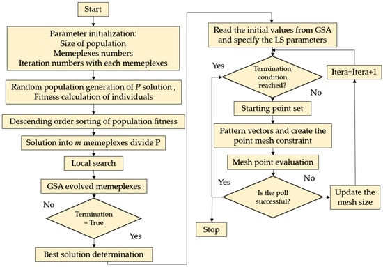
Figure 2.
Flowchart of the hGSA-LS algorithm.

Table 1.
IES, CES energy storage, and supporting devices parameters.
4. Result and Discussion
4.1. Simulation Parameters
Figure 3 shows the prediction curves of day-ahead power, cold load, heat load, and wind power of the system. The electrical, cold, thermal loads, and wind power involved in the calculation examples in this study are analyzed by referring to the data of an industrial park located in Pakistan during winter and summer.
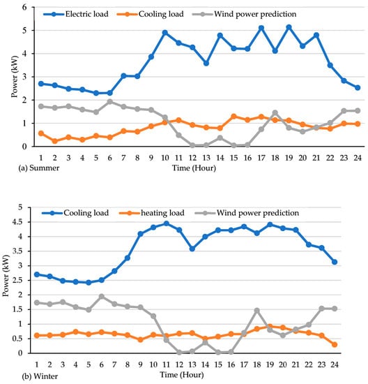
Figure 3.
Power forecast curve of electricity, cooling, heat load, and wind power in the two seasons.
The system equipment parameters are presented in Table 1, and IES is connected to the power grid and gas network. The power grid adopts a pricing strategy to reduce the operating cost of the system by using peak-valley price differences. Table 2 presents the purchase prices of natural gas and electric energy.
Table 2.
Energy unit price.
4.2. Results
This study takes the load data of an industrial park in southern Pakistan in winter and summer as an example and sets three different operational cases for comparative analysis to analyze the economic benefits generated by the CES system in IES optimal scheduling and the excellent multi-energy joint supply capacity of the CES system compared with other ESSs. In order, CES equipment, battery equipment, and no auxiliary energy storage equipment are added to IES. The three operational cases represent the scheduling situation under three different operational cases in winter and summer, respectively. In operational case l, IES joins CES, and the output of electricity, cold, and heat energy in winter and summer is shown in Figure 4.
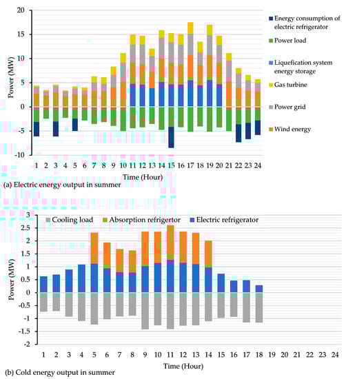
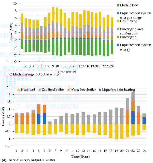
Figure 4.
Electricity and heat energy output diagram in winter under operational case 1.
Figure 5 depicts the electric power output. The CES system has a strong multi-energy regulation ability regardless in winter or summer. It stores excess wind energy in the evening when the electric load is low, the air abandoning volume is high, and electric energy is released to replenish the electric load in the daytime when the electric load is high. In terms of cold and heat output, two chillers are running on typical days in summer. Meanwhile, the CES system is used in energy storage, and it can store cold energy for the cooling load while releasing energy. The cold storage tank of the CES system can provide a cold reserve. On typical winter days, gas boilers and waste heat boilers work together. The CES system uses the stored heat energy for heat load supply and thermal reserve at the same time, which ensures a reliable cold and heat load supply. Thus, the CES system has the superior ability of the multi-type energy supply. In the second approach, batteries are added to the system, and the output of electricity, cold, and heat energy in winter and summer is shown in Figure 6. The battery has a good performance in absorbing new energy. However, the cooling load still needs to be fully supplied by absorption refrigeration electromechanical and electric chillers on a typical day in summer. The supply of heat load still depends on gas boilers and waste heat boilers on a typical day in winter.
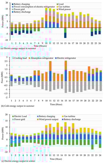
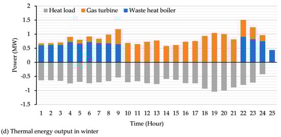
Figure 5.
Electricity and heat energy output in winter under operational case 2.
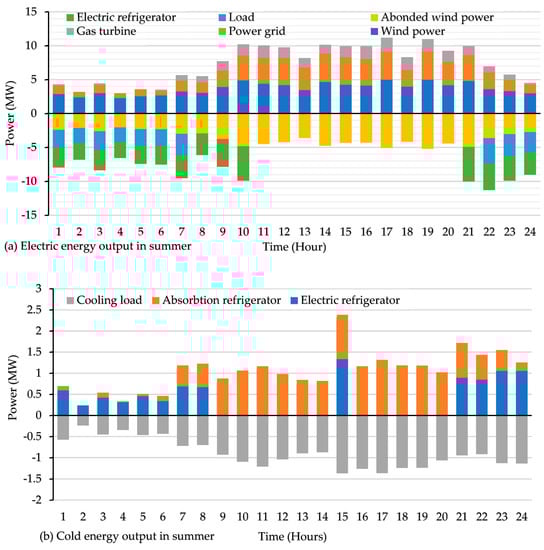
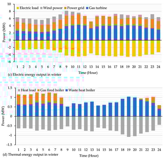
Figure 6.
Electricity and heat energy output in winter under operational case 3.
The IES under three different operational cases fluctuates between 80%, 90%, 110%, and 120% of the current price on the premise of the existing peak-valley electricity price and natural gas price. The effect of energy price fluctuation on the primary energy saving rate and operating cost of IES is analyzed. Figure 7 shows the influence of natural gas price fluctuation on system operating costs and primary energy saving rates in winter and summer. It also depicts the decline in natural gas prices.
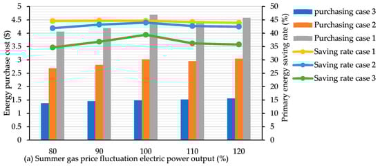
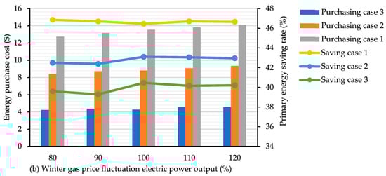
Figure 7.
Fluctuation of gas prices under the three operational cases of the IES system in winter and summer.
Figure 8 depicts the electricity price decrease. The system energy purchase cost under the three cases in typical summer days decreases accordingly, and the primary energy saving rate also has a downward trend.
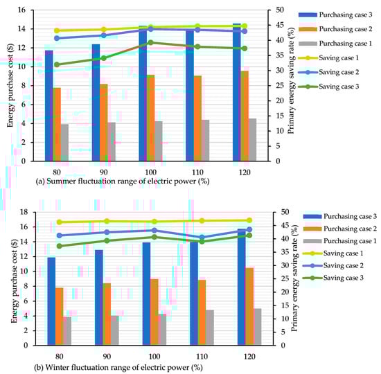
Figure 8.
Fluctuation of electricity prices under the three operational cases in winter and summer.
4.3. Discussion
In terms of multi-type energy supply, the battery is inferior to the CES system and does not have the function of multi-energy connection and supply. In addition, the battery has a short operational life and high replacement cost [17], which is not conducive to ensuring the cost of IES in the long-term operation time. In the third operational case, IES does not contain any auxiliary energy storage device. At night when the wind power is high and the electrical load demand is low, the abandoned wind power cannot be absorbed, and its electric regulation energy forcedly needs to be strengthened. In summer, the typical day and night electrical load is low, the output of the absorption refrigerator is low, the output of the electric refrigerator is more, the power purchase from the grid increases, and the gas consumption is high. On a typical day in winter, gas-fired boilers need to be run to supply heat load, and the purchase of gas increases, which affects the operating cost and carbon emissions of the system.
Table 3 depicts the energy purchase cost. Compared with those in the two other conditions, the optimization results on typical days in winter and summer show that the electricity and gas purchase costs of IES after the addition of CES are significantly lower than those before the addition of IES. In operational case 1, the energy purchase cost in summer is higher than that in winter. The reason is that the electricity in the system when supplying cooling load chillers and absorption chillers run together, which makes electricity costs slightly higher. Compared with that of operational case 1, the energy purchase cost of cases 2 and 3 is reduced. This result indicates that the CES system has a strong multi-type energy supply capacity and can effectively reduce the purchase cost of various types of energy, which reduces the total operating cost and improves the economy of IES. Table 3 compares the next energy saving rate and carbon dioxide emission reduction rate of the three different operational cases.
Table 3.
Optimization results of IES in typical days in winter and summer.
Considering the absorption of new energy, the CES system and battery also have a high quality of absorbing and abandoning wind power, both of which can improve the absorbing and abandoning wind power rate to nearly 100%. However, compared with the CES system, the battery cannot store and supply multiple types of energy. Moreover, the CES system has a long service life and is more suitable for the long-term operation of IES. On a typical day in summer, IES with CES storage increases by 1.07% compared with batteries, and CO2 emissions decrease by 0.28 t. Compared with those of IES without any energy storage equipment, the 2 indexes increase by 5.16% and decrease by 3.08 t, respectively. On a typical winter day, the next energy-saving rate of case 1 increases by 3.32% compared with that of case 2, and the carbon dioxide emission decreases by 1.32 t. Compared with those of case 3, the two indexes increase by 5.83% and decrease by 2.88 t, respectively. The variation range of the two indicators in cases 1 and 2 on a typical day in winter is more obvious than that on a typical day in summer. The reason is that the heat load in winter needs the supply of a gas boiler and waste heat boiler, while the performance of the CES system in case 1 is superior. The primary energy saving rate and carbon emission change. In summary, battery and CES can reduce the operation cost of IES and improve the absorption rate of new energy to a certain extent. However, the CES system has a more prominent ability of multi-type energy supply and regulation, which can better achieve the purpose of optimal economic operation of the system. The CES ESS also has certain advantages in the low-carbon and energy-saving operation.
As shown in Figure 7, energy purchase cost decreases on a typical day in summer. The change range of the primary energy saving rate under case 1 is about 0.1%, while that under case 2 decreases by 0.9% and 1.6%, and that under case 3 decreases by 2.8% and 2.4%. This result demonstrates that increase in gas price leads to a decrease in gas purchase volume, and the cooling capacity of the CES system offsets part of the price impact. Therefore, the CES system has stronger stability in coping with the decrease in gas prices in summer. On a typical day in winter, energy purchase cost still decreases with the gas price. However, in terms of primary energy saving rate, the system saving rate index data are stable under case 1, while the system saving rate under cases 2 and 3 decreases by 0.8% and 1.37% at 80% of gas price, respectively. With the increase in natural gas price, the energy purchase cost of the three operational cases on a typical day in summer decreases slightly to 110% of the original gas price, which implies that the system is slightly sensitive to the increase in gas price. In terms of primary energy saving rate, the index of case 2 at 110% of the original gas price is still stable. The index of cases 2 and 3 at 110% of the original gas price decreases by 1.2% and 3.17%, respectively. However, it is nearly flat with that at 110% and at 120%. Therefore, the system has an obvious response to the rising gas price in summer cases 2 and 3, but the saving rate index tends to be stable with the gradual increase in the price. On a typical winter day, the energy purchase cost of the three cases shows an upward trend. Case 1 slightly increases by 0.36% in terms of primary energy saving rate, while case 2 tends to be stable, and case 3 decreases by 0.27%. The abovementioned trend indicates that IES with CES has better performance in coping with gas price fluctuations. The reason is that the system is heated by gas boilers and waste heat boilers in winter and cooled by absorption chillers in summer. Case 1 has a CES system to assist heating and cooling, which has better stability in dealing with price fluctuations than the two other cases.
According to Figure 8, the next energy-saving rate of case 1 decreases by 0.63% and 0.57%. Those of cases 2 and 3 decreased by 2.22%, 0.9%, and 5.4%. The 2.11% is the decrease compared with case 1, which means that case 1 is more reliable when dealing with electricity price decline in summer. On a typical day in winter, the energy purchase cost gradually decreases successively. The primary energy saving rate index of case 1 is stable, while the primary energy saving rate index of case 2 decreases by 0.79% and 1.27%, and that of case 3 decreases by 1.61% and 1.97%. Case 3 has the largest drop during the rises in electricity prices, and the purchasing power of case 1 becomes typical during summer days. This price drops slightly and rises again at 120%, while case 2 has the same trend and case 3 gradually rises. In terms of primary energy saving rate, the index of case 1 is stable, case 2 slightly decreases by 0.33% and 0.61%, while case 3 decreases by 1.36% and 0.44%. On a typical day in winter, the increase in energy purchase cost is similar to that in summer. Concerning primary energy saving rate, case 1 slightly increases by 0.62%, but cases 2 and 3 have a significant downward trend at 110% of the original electricity price, and case 2 has a maximum decline of 4.38%. According to the above-mentioned analysis, case 3 cannot cope with the fluctuation of electricity prices because it has no ESS. Thus, it has the worst stability. Case 2 has the function of electricity storage and good stability, but it does not have the function of cold and heat storage. It cannot cope with the operation cost of electric refrigerators and other equipment with the fluctuation of electricity price. The stability of case 2 is also worse than that of case 1. Case 1 has the capacity of a combined supply of cold, heat, and electricity. Thus, it has the strongest ability to deal with electricity price fluctuations.
Table 4 depicts the final, comparatively best result of the various algorithms with processing time. Among various methods, the hGSA-LS algorithm shows more improvement than other algorithms. The use of the hGSA-LS algorithm enhances the total cost of the IES. Among all three cases, case 3 shows the best case of the operation of the IES. For better understanding, all algorithms for 40 trials are compared. Compared with case 2 and after considering the uncertainty of energy purchase price in case 3, the purchased electricity of the system is flexibly adjusted according to the real-time market electricity price, and the operating cost is reduced by 10.23$. Compared with that of case 2, the operating cost of case 3 increases by 81.5$ after considering scenery output and comprehensive demand response uncertainty, and the robustness of the model is improved by sacrificing certain economic benefits. The major factor in increasing the total cost is uncertainty in the problem formulation and the effect of random variables. The major factor in increasing the total cost is uncertainty in the problem formulation and the effect of random variables. The optimal operating point for the IES cannot be reached without the use of probabilistic modeling. However, the hGSA-LS algorithm greatly increases the cost.
Table 4.
Total trails (40) in all three cases.
5. Conclusions
The CES system can efficiently utilize wind and solar power and can be dispatched in the peak hours of regional power load demand to release energy. It can fill the demand gap, which is conducive to the peak regulation of the power system and further boost the rapid development of new energy.
- The CES system has a green growth system operation, flexibility, scheduling ability, and excellent operation of multi-type energy supply. Through the IES of multi-type energy supply, the economic benefits of wind are reduced. Thus, participating in the scheduling of energy consumption and other power equipment is needed to optimize the operation of the supply system.
- The low-carbon environmental protection operation adds a CES ESS to IES, which improves its primary energy saving rate and carbon emission reduction.
- In terms of sensitivity to energy prices, IES containing CES has stable price fluctuations, and its operational efficiency is higher than that of traditional IES.
- The hGSA-LS algorithm requires 5.87 s for solving the problem; however, the GA, PSO, and GSA require 12.56, 10.33, and 7.95 s, respectively. Thus, the hGSA-LS algorithm shows better time performance than other methods, such as GA, PSO, and GSA.
Author Contributions
Conceptualization, writing—original draft preparation, formal analysis: M.S.N., A.N.A. and M.S.J.; methodology, investigation: M.S.N. and A.N.A.; writing—review and editing: A.S.M.M., M.I. and P.B. All authors have read and agreed to the published version of the manuscript.
Funding
This work was funded by the Researchers Supporting Project No. (RSP-2021/363), King Saud University, Riyadh, Saudi Arabia.
Institutional Review Board Statement
Not applicable.
Informed Consent Statement
Not applicable.
Data Availability Statement
Not applicable.
Acknowledgments
Authors thank the funding by the Researchers Supporting Project No. (RSP-2021/363), King Saud University, Riyadh, Saudi Arabia.
Conflicts of Interest
The authors declare no conflict of interest.
References
- Slowik, A.; Cpalka, K. Hybrid Approaches to Nature-inspired Population-based Intelligent Optimization for Industrial Applications. IEEE Trans. Ind. Inform. 2022, 18, 546–558. [Google Scholar] [CrossRef]
- Hassan, M.H.; Houssein, E.H.; Mahdy, M.A.; Kamel, S. An improved Manta ray foraging optimizer for cost-effective emission dispatch problems. Eng. Appl. Artif. Intell. 2021, 100, 104155. [Google Scholar] [CrossRef]
- Tahmasebi, M.; Pasupuleti, J.; Mohamadian, F.; Shakeri, M.; Guerrero, J.; Khan, M.B.; Nazir, M.; Safari, A.; Bazmohammadi, N. Optimal Operation of Stand-Alone Microgrid Considering Emission Issues and Demand Response Program Using Whale Optimization Algorithm. Sustainability 2021, 13, 7710. [Google Scholar] [CrossRef]
- Tan, H.; Ren, Z.; Yan, W.; Wang, Q.; Mohamed, M.A. A Wind Power Accommodation Capability Assessment Method for Multi-Energy Microgrids. IEEE Trans. Sustain. Energy 2021, 12, 2482–2492. [Google Scholar] [CrossRef]
- Nadeem, F.; Hussain, S.M.S.; Tiwari, P.K.; Goswami, A.K.; Ustun, T.S. Comparative Review of Energy Storage Systems, Their Roles, and Impacts on Future Power Systems. IEEE Access 2018, 7, 4555–4585. [Google Scholar] [CrossRef]
- Liserre, M.; Sauter, T.; Hung, J.Y. Future Energy Systems: Integrating Renewable Energy Sources into the Smart Power Grid Through Industrial Electronics. IEEE Ind. Electron. Mag. 2010, 4, 18–37. [Google Scholar] [CrossRef]
- Borri, E.; Tafone, A.; Romagnoli, A.; Comodi, G. A review on liquid air energy storage: History, state of the art and recent developments. Renew. Sustain. Energy Rev. 2021, 137, 110572. [Google Scholar] [CrossRef]
- Mohamed, M.A.; Almalaq, A.; Abdullah, H.M.; Alnowibet, K.A.; Alrasheedi, A.F.; Zaindin, M.S.A. A Distributed Stochastic Energy Management Framework Based-Fuzzy-PDMM for Smart Grids Considering Wind Park and Energy Storage Systems. IEEE Access 2021, 9, 46674–46685. [Google Scholar] [CrossRef]
- Khadanga, R.K.; Kumar, A. Analysis of PID controller for the load frequency control of static synchronous series compensator and capacitive energy storage source-based multi-area multi-source interconnected power system with HVDC link. Int. J. Bio-Inspired Comput. 2019, 13, 131–139. [Google Scholar] [CrossRef]
- Abdalla, A.N.; Nazir, M.S.; Tao, H.; Cao, S.; Ji, R.; Jiang, M.; Yao, L. Integration of energy storage system and renewable energy sources based on artificial intelligence: An overview. J. Energy Storage 2021, 40, 102811. [Google Scholar] [CrossRef]
- Jalili, M.; Sedighizadeh, M.; Fini, A.S. Stochastic optimal operation of a microgrid based on energy hub including a solar-powered compressed air energy storage system and an ice storage conditioner. J. Energy Storage 2021, 33, 102089. [Google Scholar] [CrossRef]
- Hemmati, M.; Mirzaei, M.A.; Abapour, M.; Zare, K.; Mohammadi-Ivatloo, B.; Mehrjerdi, H.; Marzband, M. Economic-environmental analysis of combined heat and power-based reconfigurable microgrid integrated with multiple energy storage and demand response program. Sustain. Cities Soc. 2021, 69, 102790. [Google Scholar] [CrossRef]
- Mago, P.; Chamra, L. Analysis and optimization of CCHP systems based on energy, economical, and environmental considerations. Energy Build. 2009, 41, 1099–1106. [Google Scholar] [CrossRef]
- Tooryan, F.; HassanzadehFard, H.; Dargahi, V.; Jin, S. A cost-effective approach for optimal energy management of a hybrid CCHP microgrid with different hydrogen production considering load growth analysis. Int. J. Hydrogen Energy 2022, 47, 6569–6585. [Google Scholar] [CrossRef]
- Holagh, S.G.; Haghghi, M.A.; Chitsaz, A. Which methane-fueled fuel cell is of superior performance in CCHP applications; solid oxide or molten carbonate? Fuel 2022, 312, 122936. [Google Scholar] [CrossRef]
- Rostamzadeh, H.; Ebadollahi, M.; Ghaebi, H.; Shokri, A. Comparative study of two novel micro-CCHP systems based on organic Rankine cycle and Kalina cycle. Energy Convers. Manag. 2019, 183, 210–229. [Google Scholar] [CrossRef]
- Nazir, M.S.; Din, S.U.; Shah, W.A.; Ali, M.; Kharal, A.Y.; Abdalla, A.N.; Sanjeevikumar, P. Optimal Economic Modelling of Hybrid Combined Cooling, Heating, and Energy Storage System Based on Gravitational Search Algorithm-Random Forest Regression. Complexity 2021, 2021, 5539284. [Google Scholar] [CrossRef]
- Rey, G.; Ulloa, C.; Cacabelos, A.; Barragáns, B. Performance analysis, model development and validation with experimental data of an ICE-based micro-CCHP system. Appl. Therm. Eng. 2015, 76, 233–244. [Google Scholar] [CrossRef]
- Jannelli, E.; Minutillo, M.; Cozzolino, R.; Falcucci, G. Thermodynamic performance assessment of a small size CCHP (combined cooling heating and power) system with numerical models. Energy 2014, 65, 240–249. [Google Scholar] [CrossRef]
- Rashedi, E.; Nezamabadi-Pour, H.; Saryazdi, S. GSA: A Gravitational Search Algorithm. Inf. Sci. 2009, 179, 2232–2248. [Google Scholar] [CrossRef]
- Rashedi, E.; Rashedi, E.; Nezamabadi-Pour, H. A comprehensive survey on gravitational search algorithm. Swarm Evol. Comput. 2018, 41, 141–158. [Google Scholar] [CrossRef]
- Khadanga, R.K.; Satapathy, J. A new hybrid GA–GSA algorithm for tuning damping controller parameters for a unified power flow controller. Int. J. Electr. Power Energy Syst. 2015, 73, 1060–1069. [Google Scholar] [CrossRef]
- Garg, H. A Hybrid GA-GSA Algorithm for Optimizing the Performance of an Industrial System by Utilizing Uncertain Data. In Handbook of Research on Artificial Intelligence Techniques and Algorithms; IGI Global: Hershey, PA, USA, 2015; pp. 620–654. [Google Scholar] [CrossRef] [Green Version]
- Rostami, A.S.; Bernety, H.; Hosseinabadi, A. A novel and optimized algorithm to select monitoring sensors by GSA. In Proceedings of the 2nd International Conference on Control, Instrumentation and Automation, Shiraz, Iran, 27–29 December 2011. [Google Scholar]
- Ji, J.; Gao, S.; Wang, S.; Tang, Y.; Yu, H.; Todo, Y. Self-Adaptive Gravitational Search Algorithm with a Modified Chaotic Local Search. IEEE Access 2017, 5, 17881–17895. [Google Scholar] [CrossRef]
Publisher’s Note: MDPI stays neutral with regard to jurisdictional claims in published maps and institutional affiliations. |
© 2022 by the authors. Licensee MDPI, Basel, Switzerland. This article is an open access article distributed under the terms and conditions of the Creative Commons Attribution (CC BY) license (https://creativecommons.org/licenses/by/4.0/).