Abstract
Solid oxide fuel cells are energy conversion devices that contribute to carbon neutrality, with the advantages of high efficiency, clean emissions production, and distributed power generation. However, the high operating temperature of the solid oxide fuel cells causes system stability and material selection problems. In this study, we aimed to lower the operating temperature of a solid oxide fuel cell by reducing the thickness of the electrolyte via sputtering. The deposition process was conducted under various pressure conditions to find the optimal sputtering process for a gas-tight YSZ thin-film electrolyte. The gas-tightness of the YSZ electrolytes was evaluated by observing the nanostructure and cell performance. As a result, the YSZ thin-film deposited at 3 mTorr showed the best gas-tightness and cell performance. At 500 °C, 1.043 V of OCV and a maximum power density of 1593 mW/cm2 were observed. Then, X-ray diffraction was used to calculate the residual stress of the YSZ films. As a result, it was confirmed that the gas-tight film showed compressive residual stress. Through this study, we were successful in developing a room-temperature YSZ electrolyte fabrication process with excellent gas-tightness and performance. It was also proven that there is a strong relationship between the gas-tightness and residual stress. This study is expected to contribute to cost reductions and the mass production of solid oxide fuel cells.
1. Introduction
A solid oxide fuel cell (SOFC) is a high-temperature (>700 °C) energy conversion device with the advantages of clean emissions and high efficiency [1,2]. In addition, various hydrocarbons [3,4,5,6,7], bio-fuels [8], and ammonia [9,10] can be directly used as fuels without a reforming process. The solid oxide fuel cells can also be manufactured in various sizes, from kW to GW, so they can be used as distributed power sources, resulting in the effective use and transmission of electricity [11,12,13]. Despite these advantages, the SOFCs have high system prices and low durability due to their high operating temperatures [14,15]. When the operating temperature of the solid oxide can be reduced to 5–700 °C, it is possible to use relatively cheap metallic materials for the stack components, while the thermomechanical durability of the system will be significantly improved [16].
The application of nanotechnology to solid oxide fuel cells has the potential to lower the operating temperatures without significant performance or efficiency losses by reducing the thickness of the electrolyte and the size of the electrode particles. Therefore, various nanofabrication methods such as chemical vapor deposition (CVD) [17,18,19] and physical vapor deposition (PVD) [20,21,22] are being applied to the fabrication of solid oxide fuel cells. In the case of CVD, it is easy to manufacture dense films such as electrolytes because it shows excellent step coverage even for complex substrate structures [19]. On the other hand, PVD can be applied to both electrodes and electrolytes because the density of the thin film can be controlled by adjusting the deposition pressure [20]. During nanofabrication, the fabrication of all cell components with a single piece of equipment is a tremendous advantage in preventing defects and reducing costs and production times. Therefore, the PVD methods are more likely to be considered for solid oxide fuel cell production. Among the various PVD methods, sputtering is the most widely used, which results in superior film quality compared to using an evaporator and makes it easier to deposit the material over a large area than with pulsed laser deposition.
The solid oxide fuel cells fabricated through sputtering show excellent performance at temperatures below 600 °C. Several studies that evaluated the performance of SOFCs manufactured by sputtering showed a maximum power density of over 1 W/cm2 at such temperatures [20,21]. This high performance was due to the ultra-thin electrolyte and the well-oriented nanofibrous electrode, which showed significantly reduced ohmic and polarization losses. In addition, sputtering is also used to form an electrolyte and diffusion barrier layer for metal-supported solid oxide fuel cells due to the advantages of the room-temperature process [23,24,25].
As mentioned above, the nanostructure of the thin film produced through sputtering is changed by the deposition pressure [26]. At low sputtering pressure, the particles ejected from the target reach the substrate with high energy because the number of collisions with the background gas is minimized. These highly energetic particles enhance the surface diffusion and migration, meaning dense and flat surface structures are observed. At high sputtering pressure, the collision between the particles and the background gas becomes active, so the energy of the particles is reduced and they impact on the substrate at a low oblique angle. Since these low-energy particles minimize the surface diffusion and the adatom incident with an oblique angle promotes a shadowing effect, a porous film is generated. Therefore, the electrolytes in the solid oxide fuel cells are deposited at low pressure, and the electrodes are deposited at high pressure.
Assuming the electrolytes are manufactured through sputtering on the porous supports, the diameter of columns must grow via active surface diffusion to ensure the gas-tightness. The surface diffusion of the adatoms can be promoted by increasing the temperature of the substrate, but it is disadvantageous in terms of the cost and process time. Therefore, this research aimed to develop a room-temperature sputtering process for thin-film electrolytes for SOFCs that ensures gas-tightness. Additionally, we wanted to investigate the correlation between the residual stress and gas-tightness. According to Figure 1, the gas-tight electrolytes have an increasing diameter of columns by thickness, which inevitably generates compressive residual stress on the surface of the deposited film. Therefore, there is a close relationship between the residual stress and the gas-tightness of the electrolytes. In order to control the nanostructure of the sputtered electrolytes, deposition was carried out at various pressures, and we analyzed the surface and cross-sectional images as well as the residual stress of the films. For the calculation of residual stress, an X-ray diffraction analysis was used. When residual stress occurs, the lattice parameters are changed, which appears as an angle shift in the XRD image [27,28]. Therefore, the difference in the peak angles of the YSZ thin-films was analyzed, and the residual stress was calculated through these data. The YSZ films were also applied to the solid oxide fuel cells to observe the performance and gas-tightness. An anodized aluminum oxide (AAO) substrate was used as the porous support for thin-film solid oxide fuel cells, since it has uniform pore size and distribution [20,21]. The highly ordered and low-tortuosity pore structure of the AAO enables sufficient gas supply, even with small pore sizes of several tens to hundreds of nanometers. Additionally, this nanostructure and the small pore size provide a gas-tight thin-film electrolyte with a minimum thickness. Ni and Pt were used as the anode and cathode electrode materials, respectively, and yttria-stabilized zirconia (YSZ) was used as the electrolyte.
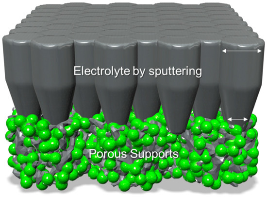
Figure 1.
Illustration of a thin-film solid oxide fuel cell in which the column diameter of the gas-tight electrolyte grows with the thickness (white arrow indicates the diameter of the column, which increases with thickness and causes compressive residual stress in the film).
2. Experimental Details
2.1. Properties and Experimental Procedures of Thin Films
A commercial sputter device (Korea Vacuum Tech Systems Co., Ltd., Gimpo, Korea) was used to fabricate thin-film electrodes and electrolytes. Ni (purity 99.9%, Vaccum Thin-film Materials, Daegu, Korea), Pt (99.99% purity, RND Korea, Gwangmyeong, Korea), and 8% yttria-stabilized zirconia (purity 99.9%, Vaccum Thin-Film Materials, Daegu, Korea) were used for the anode, cathode, and electrolyte, respectively. Here, 1 cm × 1 cm, 1-µm-thick, and 250 nm pore-sized AAO (InRedox, Longmont, CO, USA) templates were used as the porous substrates. First, the Ni anode was deposited by DC sputtering on the AAO template with the condition of 200 W of DC power and 50 mTorr of sputtering pressure. Then, the YSZ electrolyte was deposited with different sputtering pressures (3 mTorr, 5 mTorr, 10 mTorr and 20 mTorr) with 75 W of RF power. Finally, a platinum cathode was deposited on the sputtered YSZ layer with a DC power of 100 W and 50 mTorr of sputtering pressure.
2.2. Cell Characterization
To investigate the crystal structure and residual stress of the films, high-resolution X-ray diffraction (XRD) was conducted with a D8-Discovery instrument (Bruker, Munich, Germany). The FE-SEM images were taken using an SU8220 instrument (Hitachi High-Technologies, Tokyo, Japan) and an accelerating voltage of 10 kV was used for all the FE-SEM processes. The cross-sectional images of the cells were analyzed using an FEI Helios NanoLab 450 (FEI, Milpitas, CA, USA) dual-beam focused ion beam (FIB) instrument.
2.3. Electrochemical Evaluation
First, we used silver paste (Alfa Aesar, Tewksbury, MA, USA) to bond the silver wires and the cell, then Ceramabond (571-P, AREMCO, Valley Cottage, NY, USA) was applied to the cell for gas sealing. The furnace was heated up to 500 °C, then dry hydrogen gas (concentration 99.999%, produced by DEOKYANGGAS, Ulsan, Korea) was introduced into the anode side with a mass flow of 10~15 sccm and the cathode was exposed to the atmosphere for the natural air supply. A Gamry Interface 1000 Potentiostat/Galvanostat/ZRA system was used for the electrochemical data collection.
3. Results and Discussion
3.1. Nanostructure Analysis of Thin-Film Fuel Cells
Figure 2 shows the FE-SEM surface images of the YSZ films deposited under different sputtering pressures. With the increase in sputtering pressure, the size of the surface grain gradually decreased. Compared with the 5, 10, and 20 mTorr deposited YSZ films, the surface image of the 3 mTorr deposited YSZ shows a larger grain and gas-tight surface. Under low sputtering pressure, particles with high kinetic energy reach the substrate and promote surface diffusion and migration to grow columns with a larger diameter and high density [26]. Under high sputtering pressure, the porosity of the film increases due to the lower kinetic energy of the sputtered atoms from the target. When the particles with lower kinetic energy reach the substrate, the mutual bonding force between particles and the migration of the particle are reduced [29].
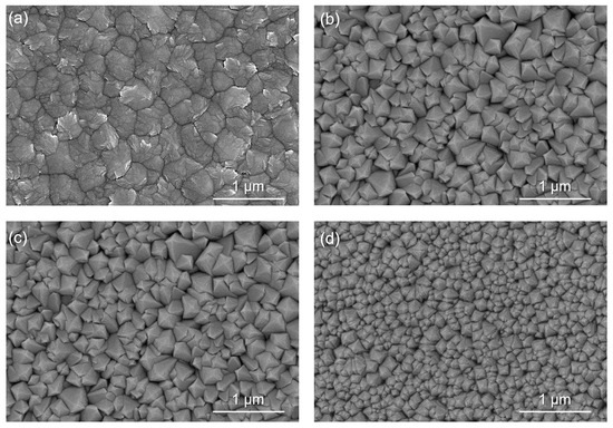
Figure 2.
SEM surface images of YSZ electrolytes deposited at sputtering pressures of (a) 3 mTorr, (b) 5 mTorr, (c) 10 mTorr, and (d) 20 mTorr.
The cross-sectional structure of YSZ deposited at 3 mTorr shown in Figure 3 showed a dense and gas-tight structure like the surface image. However, as the deposition pressure increases from 5 to 20 mTorr, the grain and diameter of YSZ columns become smaller. In these cases, numerous nanopores are generated in the films, which results in poor gas tightness.
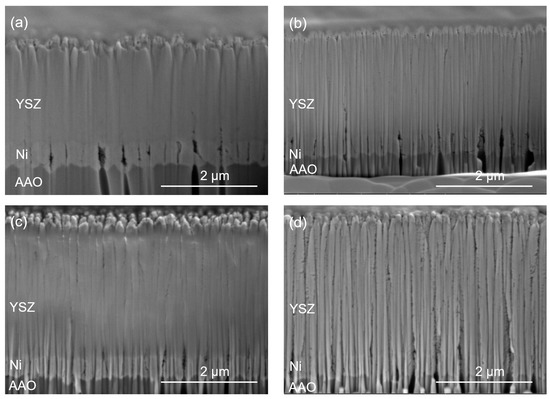
Figure 3.
FIB-Cross sectional images of YSZ electrolytes deposited on AAO/Ni at sputtering pressures of (a) 3 mTorr, (b) 5 mTorr, (c) 10 mTorr and (d) 20 mTorr.
3.2. Electrochemical Evaluation of Thin-Film Fuel Cells
AAO-supported thin-film SOFCs were fabricated to analyze the effect of the deposition pressure on the electrolyte fabrication. The cell configuration and cross-sectional FE-SEM images are shown in Figure 4. The electrochemical characterization was carried out at 500 °C, and the corresponding electrochemical characterization results are shown in Figure 5. The open-circuit voltage (OCV) values of the electrolyte films prepared at 3 mTorr and 5 mTorr sputtering pressures were 1.043 V and 0.735 V, respectively. As with the analysis results on the surface and cross-sectional images, the OCV close to the theoretical value [2] was measured at 3 mTorr, showing excellent gas-tightness. In the case of the 5 mTorr deposited YSZ, the OCV began to be reduced by gas leakage, and no OCV was seen for the 10 mTorr and 20 mTorr deposited YSZ films. The maximum power density was 1.593 W/cm2 for the 3 mTorr deposited YSZ, which was nearly the highest among YSZ-based solid oxide fuel cells [20]. Therefore, the sputtering conditions of 3 mTorr at room temperature in this research resulted in excellent ion conductivity and gas-tightness [21].
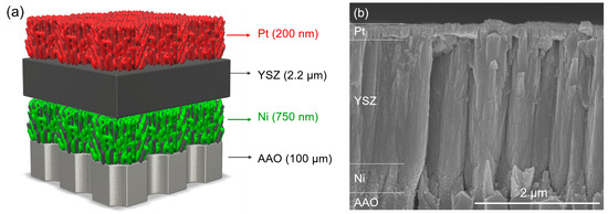
Figure 4.
(a) Illustration of an AAO-based thin-film SOFC. (b) Cross-sectional FE-SEM images of YSZ electrolytes deposited on AAO substrates at 3 mTorr.
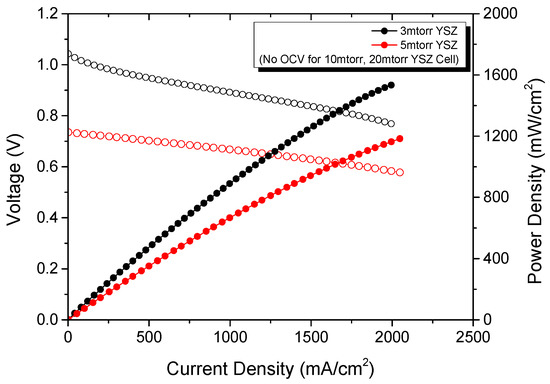
Figure 5.
I-V and I-P curves of AAO-based TF-SOFCs with different YSZ electrolytes at 500 °C.
3.3. Analysis of Residual Stress through XRD
As shown in Figure 6, XRD was used to analyze the crystallinity and residual stress values of the YSZ films made with different deposition pressures. The XRD patterns of each film mainly show peaks in the direction of (200), (222), and (400) corresponding to the cubic-phase YSZ. The three peaks (34–36°, 61–62°, and 71–75°) of YSZ were selected to calculate the residual stress. With the increase in sputtering pressure, the angle of the XRD peak increases, indicating that the stress state changes from compressive to tensile stress [30]. Mainly the 3 mTorr deposited YSZ films exhibit significant compressive stress. The increased diameter of the individual column by thickness generates compressible residual stress, resulting in a dense and gas-tight film. As the sputtering pressure increases, different sizes of the vacancies are formed during the film deposition, and the presence of these vacancies leads to tensile residual stress. Therefore, the thin-film electrolyte of the solid oxide fuel cell must exhibit compressive stress for gas-tightness.
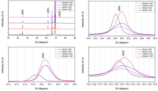
Figure 6.
X-ray diffraction investigation of the crystallinity and residual stress values of each electrolyte (3, 5, 10, and 20 mTorr YSZ).
According to Bragg’s law, we can calculate the lattice distance d using Formula (1). When the lattice distance is larger than the normal phase, this indicates residual stress in the plane direction of the film:
where d is the distance between parallel atomic planes, λ is the wavelength of the incident wave, and θ is the angle between the incident light and the crystal plane. After obtaining the distance d between the planes of the parallel atoms, the residual stress was calculated using Formula (2):
where E is Young’s modulus, ν is Poisson’s ratio, and and are the lattice spacing without stress and the lattice spacing with stress, respectively. Then, we calculated that the residual stress values of 3 mTorr in Figure 6 were 169.983 MPa, 160.292 MPa, and 154.960 MPa, respectively, which were larger than the other electrolyte films.
In Figure 7, the relations between the gas-tightness and residual stress are illustrated. To deposit a gas-tight thin-film electrolyte on the porous electrode, the diameter of the individual column must grow via active surface diffusion, which inevitably causes compressive residual stress. At low sputtering pressure, the diameter of the column is significantly increased through active surface migration and the diffusion of high-energy adatoms. Under high sputtering pressure, the energy of the adatoms is lowered due to the active collision of a background gas, which maintains the original diameters of the columns. Therefore, the gas-tight 3 mTorr deposited YSZ film shows a proper OCV, but the YSZ films deposited at 5, 10, and 20 mTorr, where gas-tightness is not ensured, show reduced or no OCV. Therefore, this study indicates a close relationship between the gas-tightness and residual stress.

Figure 7.
The tendency for residual stress for YSZ films deposited under (a) low sputtering pressure and (b) high sputtering pressure.
4. Conclusions
This study successfully developed a room-temperature sputtering process for producing thin-film solid oxide fuel cell electrolytes. The thin-film YSZ electrolytes were deposited at 3, 5, 10, and 20 mTorr to control the gas-tightness and nanostructures. According to the experimental results, the sputtering pressures caused significant differences in the nanostructure and gas-tightness of the YSZ films. The decreased deposition pressure of YSZ film resulted in denser and larger grains. On the other hand, the YSZ thin film with increased sputtering pressure showed a smaller grain size and numerous nanopores between the YSZ columns.
Furthermore, the films changed from showing compressive to tensile stress with increased sputtering pressure. The existence of tensile stress promotes the grains’ vertical growth, resulting in the generation of pores in the films. XRD was used to measure the residual stress, and it was possible to conveniently derive a relationship between the residual stress and gas-tightness. As a result, the thin film exhibited the densest and most gas-tight film morphology under the sputtering pressure of 3 mTorr, and it showed around 160 MPa of compressive stress. These YSZ films were applied to the thin-film solid oxide fuel cell, and the electrochemical properties were measured. At 500 °C, a thin-film fuel cell with a 2.20-μm-thick YSZ electrolyte deposited at 3 mTorr showed a 1.043 V OCV and 1.593 W/cm2 peak power density at 2 A/cm2, which was one of the best performances among the YSZ-based solid oxide fuel cells. The solid oxide fuel cell developed through this research showed very good performance, even though the operating temperature was lowered by more than 200 °C compared to the conventional solid oxide fuel cells. It is believed that this research will contribute to solving the current climate and energy problems.
Author Contributions
Conceptualization: Y.T.; methodology: H.Y.L. and H.L.; supervision: Y.H.L.; writing—original draft preparation: Y.T.; writing—review and editing: Y.H.L. and H.L. All authors have read and agreed to the published version of the manuscript.
Funding
This work was supported by the Ministry of Education of the Republic of Korea, the National Research Foundation of Korea (No. 2020R1G1A1014777), and the Korea Institute of Energy Technology Evaluation and Planning (KETEP), with financial resources granted by the Ministry of Trade, Industry, and Energy, Republic of Korea (No. 20213030030150). This result was supported by "Regional Innovation Strategy (RIS)" through the National Research Foundation of Korea(NRF), funded by the Ministry of Education (MOE) (2021RIS-003).
Institutional Review Board Statement
Not applicable.
Informed Consent Statement
Not applicable.
Data Availability Statement
Data are available from the corresponding author on request.
Conflicts of Interest
The authors declare no conflict of interest.
References
- Minh, N.Q. Ceramic fuel cells. J. Am. Ceram. Soc. 1993, 76, 563–588. [Google Scholar] [CrossRef]
- O’hayre, R.; Cha, S.W.; Colella, W.; Prinz, F.B. Fuel Cell Fundamentals; John Wiley & Sons: Hoboken, NJ, USA, 2016. [Google Scholar]
- Sengodan, S.; Choi, S.; Jun, A.; Shin, T.H.; Ju, Y.W.; Jeong, H.Y.; Shin, J.; Irvine, J.T.; Kim, G. Layered oxygen-deficient double perovskite as an efficient and stable anode for direct hydrocarbon solid oxide fuel cells. Nat. Mater. 2015, 14, 205–209. [Google Scholar] [CrossRef] [PubMed]
- Murray, E.P.; Tsai, T.; Barnett, S.A. A direct-methane fuel cell with a ceria-based anode. Nature 1999, 400, 649–651. [Google Scholar] [CrossRef]
- Liu, F.; Duan, C. Direct-hydrocarbon proton-conducting solid oxide fuel cells. Sustainability 2021, 13, 4736. [Google Scholar] [CrossRef]
- McIntosh, S.; Gorte, R.J. Direct hydrocarbon solid oxide fuel cells. Chem. Rev. 2004, 104, 4845–4866. [Google Scholar] [CrossRef]
- Thieu, C.A.; Ji, H.I.; Kim, H.; Yoon, K.J.; Lee, J.H.; Son, J.W. Palladium incorporation at the anode of thin-film solid oxide fuel cells and its effect on direct utilization of butane fuel at 600 °C. Appl. Energy 2019, 243, 155–164. [Google Scholar] [CrossRef]
- Da Silva, A.A.A.; Steil, M.C.; Tabuti, F.N.; Rabelo-Neto, R.C.; Noronha, F.B.; Mattos, L.V.; Fonseca, F.C. The role of the ceria dopant on Ni/doped-ceria anodic layer cermets for direct ethanol solid oxide fuel cell. Int. J. Hydrog. Energy 2021, 46, 4309–4328. [Google Scholar] [CrossRef]
- Rathore, S.S.; Biswas, S.; Fini, D.; Kulkarni, A.P.; Giddey, S. Direct ammonia solid-oxide fuel cells: A review of progress and prospects. Int. J. Hydrog. Energy 2021, 46, 35365–35384. [Google Scholar] [CrossRef]
- Song, Y.; Li, H.; Xu, M.; Yang, G.; Wang, W.; Ran, R.; Zhou, W.; Shao, Z. Infiltrated NiCo alloy nanoparticle decorated perovskite oxide: A highly active, stable, and antisintering anode for direct-ammonia solid oxide fuel cells. Small 2020, 16, 2001859. [Google Scholar] [CrossRef]
- Damo, U.M.; Ferrari, M.L.; Turan, A.; Massardo, A.F. Solid oxide fuel cell hybrid system: A detailed review of an environmentally clean and efficient source of energy. Energy 2019, 168, 235–246. [Google Scholar] [CrossRef] [Green Version]
- Singh, M.; Zappa, D.; Comini, E. Solid oxide fuel cell: Decade of progress, future perspectives and challenges. Int. J. Hydrog. Energy 2021, 46, 27643–27674. [Google Scholar] [CrossRef]
- Stambouli, A.B.; Traversa, E. Solid oxide fuel cells (SOFCs): A review of an environmentally clean and efficient source of energy. Renew. Sustain. Energy Rev. 2002, 6, 433–455. [Google Scholar] [CrossRef]
- Fan, L.; Zhu, B.; Su, P.C.; He, C. Nanomaterials and technologies for low temperature solid oxide fuel cells: Recent advances, challenges and opportunities. Nano Energy 2018, 45, 148–176. [Google Scholar] [CrossRef]
- Wachsman, E.D.; Lee, K.T. Lowering the temperature of solid oxide fuel cells. Science 2011, 334, 935–939. [Google Scholar] [CrossRef]
- Brett, D.J.; Atkinson, A.; Brandon, N.P.; Skinner, S.J. Intermediate temperature solid oxide fuel cells. Chem. Soc. Rev. 2008, 37, 1568–1578. [Google Scholar] [CrossRef]
- Shim, J.H.; Chao, C.-C.; Huang, H.; Prinz, F.B. Atomic Layer Deposition of Yttria-Stabilized Zirconia for Solid Oxide Fuel Cells. Chem. Mater. 2007, 19, 3850–3854. [Google Scholar] [CrossRef]
- Choi, H.J.; Bae, K.; Grieshammer, S.; Han, G.D.; Park, S.W.; Kim, J.W.; Shim, J.H. Surface tuning of solid oxide fuel cell cathode by atomic layer deposition. Adv. Energy Mater. 2018, 8, 1802506. [Google Scholar] [CrossRef]
- An, J.; Kim, Y.B.; Park, J.; Gür, T.M.; Prinz, F.B. Three-dimensional nanostructured bilayer solid oxide fuel cell with 1.3 W/cm2 at 450 °C. Nano Lett. 2013, 13, 4551–4555. [Google Scholar] [CrossRef]
- Lee, Y.H.; Ren, H.; Wu, E.A.; Fullerton, E.E.; Meng, Y.S.; Minh, N.Q. All-sputtered, superior power density thin-film solid oxide fuel cells with a novel nanofibrous ceramic cathode. Nano Lett. 2020, 20, 2943–2949. [Google Scholar] [CrossRef]
- Ren, H.; Lee, Y.H.; Wu, E.A.; Chung, H.; Meng, Y.S.; Fullerton, E.E.; Minh, N.Q. Nano-ceramic cathodes via Co-sputtering of Gd–Ce alloy and lanthanum strontium cobaltite for low-temperature thin-film solid oxide fuel cells. ACS Appl. Energy Mater. 2020, 3, 8135–8142. [Google Scholar] [CrossRef]
- Chang, I.; Ji, S.; Park, J.; Lee, M.H.; Cha, S.W. Ultrathin YSZ coating on Pt cathode for high thermal stability and enhanced oxygen reduction reaction activity. Adv. Energy Mater. 2015, 5, 1402251. [Google Scholar] [CrossRef]
- Udomsilp, D.; Rechberger, J.; Neubauer, R.; Bischof, C.; Thaler, F.; Schafbauer, W.; Menzler, N.H.; de Haart, L.G.; Nenning, A.; Opitz, A.K.; et al. Metal-supported solid oxide fuel cells with exceptionally high power density for range extender systems. Cell Rep. Phys. Sci. 2020, 1, 100072. [Google Scholar] [CrossRef]
- Klemensø, T.; Nielsen, J.; Blennow, P.; Persson, Å.H.; Stegk, T.; Christensen, B.H.; Sønderby, S. High performance metal-supported solid oxide fuel cells with Gd-doped ceria barrier layers. J. Power Sources 2011, 196, 9459–9466. [Google Scholar] [CrossRef]
- Sønderby, S.; Klemensø, T.; Christensen, B.H.; Almtoft, K.P.; Lu, J.; Nielsen, L.P.; Eklund, P. Magnetron sputtered gadolinia-doped ceria diffusion barriers for metal-supported solid oxide fuel cells. J. Power Sources 2014, 267, 452–458. [Google Scholar] [CrossRef] [Green Version]
- Thornton, J.A. Structure-zone models of thin films. In Modeling of Optical Thin Films; SPIE: Bellingham, WA, USA, 1988; Volume 821, pp. 95–105. [Google Scholar]
- Mani, A.; Aubert, P.; Mercier, F.; Khodja, H.; Berthier, C.; Houdy, P. Effects of residual stress on the mechanical and structural properties of TiC thin films grown by RF sputtering. Surf. Coat. Technol. 2005, 194, 190–195. [Google Scholar] [CrossRef]
- Xi, Y.; Gao, K.; Pang, X.; Yang, H.; Xiong, X.; Li, H.; Volinsky, A.A. Film thickness effect on texture and residual stress sign transition in sputtered TiN thin films. Ceram. Int. 2017, 43, 11992–11997. [Google Scholar] [CrossRef]
- Kusano, E. Structure-zone modeling of sputter-deposited thin films: A brief review. Appl. Sci. Converg. Technol. 2019, 28, 179–185. [Google Scholar] [CrossRef]
- Bunting, A.; Cheung, R. Evaluation of residual stress in sputtered tantalum thin-film. Appl. Surf. Sci. 2016, 371, 571–575. [Google Scholar]
Publisher’s Note: MDPI stays neutral with regard to jurisdictional claims in published maps and institutional affiliations. |
© 2022 by the authors. Licensee MDPI, Basel, Switzerland. This article is an open access article distributed under the terms and conditions of the Creative Commons Attribution (CC BY) license (https://creativecommons.org/licenses/by/4.0/).