Abstract
Without demolishing an entire existing building, it is possible to sustainably expand its underground spaces to enhance the building’s functionality. However, there have been a few relevant studies exploring this option, and they did not consider the financial feasibilities of underground vertical extension methods. Therefore, this paper analyzes the economic impacts of three sustainable vertical extension methods for existing underground spaces. The extension methods were the (1) bottom-up, (2) normal top-down, and (3) top-down with multi-post downward (MPD) methods. In order to analyze and compare the economic impacts of the underground vertical extension methods, 24 illustrative examples were generated in this paper. Construction costs of the three sustainable vertical extension methods for existing underground spaces are calculated and compared. Those are based on the quantity of used materials in the construction phase and dismantled materials in the demolition phase, as well as unit costs of each material. In addition, the structural stabilities of the examples are analyzed using MIDAS Gen 2017. As the results, the top-down method with MPD was the lowest sustainable method for vertically expanding underground spaces compared to other two methods under the same condition. Moreover, the higher the number of underground floors of existing buildings and the greater the number of extended basement floors, the more economically advantageous was the top-down method with MPD. Considering their structural stabilities and economic impacts of the extension methods help practitioners to select appropriate construction techniques and reduce costs, risks, and the amount of generated construction and demolition waste.
1. Introduction
The use of underground space in buildings in congested urban areas has been increasing since there is a lack of available aboveground space [1,2,3,4] and the development of additional underground space in existing cities can provide new potential for urban development [5]. Underground structures have significant impacts on the environment [4,6] and underground space can reduce environmental contamination and improve the quality of the environment [2,7]. Regardless of stability of existing buildings, sometimes buildings have been demolished and newly constructed due to the lack of underground parking spaces or aging of mechanical, electrical, and plumbing (MEP) facilities [8]. Excessive demolition and new construction of existing buildings increase the amount of generated construction and demolition (C&D) waste [8]. Without demolishing an entire building, it is possible to sustainably expand its underground spaces vertically and horizontally to enhance the functionality. It can be an opportunity to reduce the amount of generated C&D waste and create sustainable urban development in existing cities. However, there are relatively few cases of vertically expanding underground spaces in buildings because of several challenges, such as the difficulty of risk management related to construction of underground structures and minimization of structural effects on ground floors of existing and surrounding buildings. To address the challenges of vertical extensions for underground spaces in existing buildings, a few previous approaches have been conducted: (1) practical case studies on vertical extensions of underground spaces in existing buildings [9,10,11,12], (2) development of a connection system between existing piles and new piles installed for extended underground spaces [13], and (3) development of vertical underground extension processes for existing buildings [14,15,16]. Bing [10] introduced an application case of a floating underground extension method for expanding parking lot spaces in residential buildings, where the floating extension method excavates the area underneath the existing building to extend it vertically downward without destroying the building. They also derived factors influencing the extension planning and structural stability of existing buildings. Kim, Bang, and Lim [13] proposed a system to connect piles installed in existing underground spaces with foundations newly constructed for extended underground spaces. It helped secure structural stability and reduce the number of reinforcement piles. However, the construction processes were to be complicated, because temporary micro-piles and frames should be installed during excavation and dismantled for the vertical underground extension in the proposed connection system. Park, Lew, Choi, and Lee [14] introduced a floating underground space extension method applied to actual sites for the preservation and expansion of cultural-heritage buildings. After excavation, double-tube micro-piles and jack-up systems were used for supporting the buildings. Kim, Lee, Kim, Koo, Jung, and Seo [15] and Jung, Kim, Lee, Hwang, and Seo [16] proposed a new conceptual construction process involving floating methods for expanding existing buildings and conceptually arranged the process for selecting the most suitable method among various construction methods according to characteristics of each site. Selection processes for appropriate construction techniques can influence both the time and costs of construction, as well as the environment [17].
Sustainable vertical extension methods for underground spaces without demolishing existing buildings may vary depending on site conditions of architecture, engineering, and construction (AEC) projects. However, previous studies did not consider detailed excavation and construction processes based on various site conditions. In particular, they did not analyze the economic feasibility of the proposed underground vertical extension methods for existing buildings. Therefore, a process to analyze economic impacts of three sustainable vertical extension methods of existing underground spaces is proposed based on the quantity of used or demolished materials on site. The three sustainable methods are bottom-up, normal top-down, and top-down multiple posts downward (MPDs) methods. To analyze their economic impacts, construction costs of 24 illustrative examples to which three sustainable vertical extension methods for existing underground spaces are applied, are calculated, and compared. In addition, their structural stabilities are also analyzed using MIDAS Gen 2017.
The structure of this paper is as follows. Section 2 describes the materials and research methods used in this paper. Section 3 includes processes and details of three sustainable vertical extension methods for underground spaces in existing buildings. Section 4 describes the overview of the 24 illustrative examples. Section 5 includes results of the structural analyses with the three sustainable vertical extension methods for underground spaces in existing buildings. In Section 6, the economic impacts of the three sustainable vertical extension methods for underground spaces in the illustrative examples are analyzed, followed by discussion and conclusions in Section 7.
2. Materials and Methods
Figure 1 shows an overall research process of this paper which analyzes structural stabilities and economic impacts of the three sustainable vertical extension methods of existing underground spaces. The three sustainable methods considered in this paper are as follows:
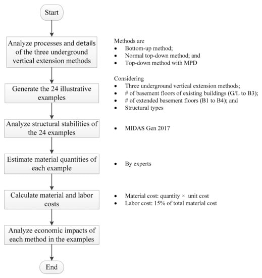
Figure 1.
The research process.
- (1)
- Bottom-up method: the construction of floor structures to be extended are carried out after finishing all of the excavation of the soil under the existing building.
- (2)
- Normal top-down method: the construction of each floor structure to be extended is carried out after finishing the excavation of soil to just below one floor under the existing building and the process is repeated up to the construction of the bottom.
- (3)
- Top-down with multiple posts downward (MPDs) method: the construction procedure is the same as that of the normal top-down method but it uses multiple posts for supporting the existing building.
Vertically expanding underground spaces of existing building with basement floors is a complex task since many perspectives, such as economic, structural stability, and environmental perspectives should be considered. The details and processes of the three sustainable extension methods are described in Section 3. In order to analyze the economic impacts of the three sustainable methods, 24 illustrative examples were generated through considering the number of basement floors of existing buildings, the number of basement floors that are vertically extended, and whether demolition works are included or not. Prior to economic analyses of the three underground vertical extension methods, their structural stabilities should be reviewed. The structural stabilities of the illustrative examples were analyzed using MIDAS Gen 2017 in this paper. The reliability of the program was verified earlier by comparing it with other analysis programs [18]. Currently, the program is used for structural analysis of almost all buildings in South Korea.
The calculated vertical underground extension cost of the 24 illustrative examples consisted of material and labor costs. Material costs were classified as reinforcement, demolition, earthworks, structural frame construction, and finishing costs. The material cost of each work type was calculated by multiplying the quantity and unit price of materials required for the vertical extension of an underground space. The quantity of materials was estimated by an expert considering the size, the number, and position of all members assumed for the structural analyses. The working experience of the experts who participated in the process was approximately 20 years. The labor cost is generally assumed as 15% of total material cost for underground construction works in South Korea. Based on calculated material and labor costs of each case, their economic impacts were analyzed and compared.
3. Sustainable Vertical Extension Methods for Underground Spaces in Existing Buildings
In this paper, the three sustainable vertical extension methods used for underground spaces in existing buildings were the bottom-up, normal top-down, and top-down with MPDs methods. In selecting a vertical extension method for this paper, two conditions were considered: (1) a building has more than one basement floor, and (2) an existing underground structure can be demolished or reused for vertical extensions. The normal top-down and bottom-up methods can be used for vertically expanding underground spaces after demolishing existing underground structures [19]. The top-down method with MPD can expand underground space without demolishing existing underground structures.
The top-down method, which is widely used in congested AEC projects, helps secure the safety of retaining walls and work spaces and reduce construction duration [1,20]. To apply the top-down method for sustainable vertical extension of existing underground spaces, columns should be installed in the ground prior to excavation. In most cases, the basement floors of existing buildings are generally demolished prior to the installation of columns to enhance constructability. A percussion rotary drill (PRD) is commonly used for installing columns. However, a PRD has large diameter and is relatively expensive. Therefore, it is not recommended for vertical extension of underground spaces if an existing building has less than three basement floors; normally the existing floors of a South Korean residential building include one or two floors for parking lots. On the other hand, the MPD method uses augur equipment, so that it is possible to use a small diameter post such as micro piles. If the installed MPDs have sufficient resistance to support the existing building without any additional supports during the excavation, the top-down method with MPDs can be used without the removal of existing underground structures. In particular, the top-down method with MPDs is more efficient for vertically downward expanding underground spaces in urban areas because of the lack of available spaces for construction and demolition. The installed temporary multiple posts could be reused after disassembly. The bottom-up method is a common construction technique. It includes an open-cut method with struts to install retaining walls. It is easy to trigger the collapse of retaining walls or cracks in the structures of surrounding buildings because of settlement of the surrounding ground. Therefore, a careful design is required to avoid stress concentration on a part during the dismantlement of temporary struts. The top-down method of constructing the structure of building along with the excavation can be a relatively safe construction.
To select an appropriate vertical extension method for the site with existing underground structure, relevant drawings and geological conditions on site should be carefully reviewed [8]. Figure 2 shows a process to select an appropriate vertical extension method based on the several site conditions. The net distance between the basement outer wall of the targeted existing building and the outer wall of the adjacent building should be at least 1.2 m [21]. Otherwise, the distance is too short to construct an earth retaining wall between these buildings. In this case, the earth retaining wall should be installed inside the structure of the existing building. Consequently, the useful area of underground spaces after vertical underground extension is to be reduced. In this paper, the net distance between two walls is assumed to be more than 1.2 m. The processes and details of the three vertical extension methods for existing underground spaces are described in the following sub-sections.
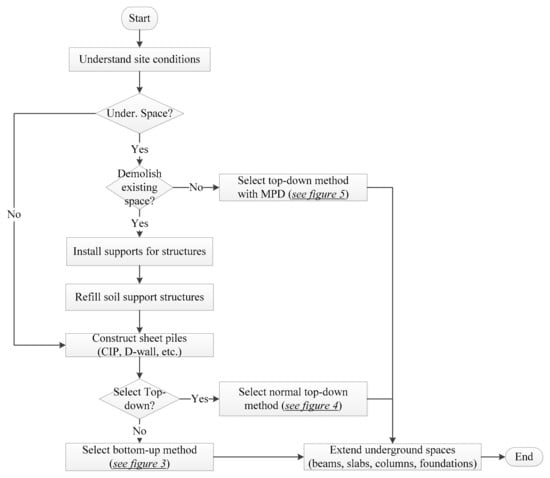
Figure 2.
The process to select an appropriate vertical extension method for underground spaces in existing buildings by considering site conditions.
3.1. Bottom-Up Method with Struts
The vertical underground extension using the bottom-up method constructs structural frames after completing excavation to foundation levels using temporary struts. Figure 3 represents the construction process of the bottom-up method with struts, from the first basement level to the third basement level. Underground spaces were extended vertically after demolishing the basements of the existing building. Before demolishing, the existing structure needed to be reinforced with temporary members to support the weight of the equipment for installing the new retaining walls (Figure 3b). After Installing retaining walls, temporary struts and H-piles were installed to provide horizontal and vertical structural stability for the underground space during the dismantling of the existing structure and the excavation for an extension. The vertical interval of the struts was 2.5 m. Structural frames for the underground space were constructed from the lowest bottom level to the ground level. After the structural frame of a floor was completed, the temporary members installed on the floor such as struts were removed, as shown in Figure 3e.
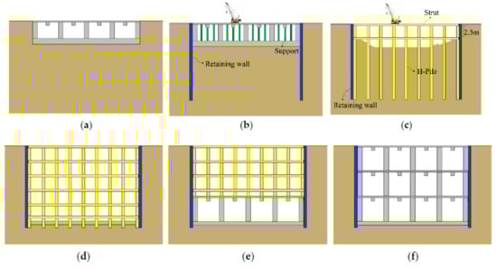
Figure 3.
Vertical extension process for existing underground spaces using the bottom-up method (from a building with one basement floor to three basement floors). The process is listed as: (a) Existing underground structures before works; (b) Installing of earth retaining walls after reinforcing the existing structure; (c) Construction of temporary struts and H-piles after demolition of the existing structure; (d) Foundation construction after Installing of struts up to base; (e) Construction of a structural frame (from B3 to B1) and dismantling struts; and (f) Completion.
3.2. Normal Top-Down Method
The vertical extension using the normal top-down method constructs structural frames sequentially from the first basement level to the lowest bottom level [19]. The constructed frames, such as slabs and beams, support earth retaining walls instead of temporary struts [15]. Furthermore, construction costs can be reduced because laborers can work on the constructed slabs [15]. However, it is difficult to excavate and install formworks (within the narrow space) under the constructed slab [15]. As bottom-up method with struts, the existing structure needed to be reinforced with temporary members for supporting the weight of the equipment for installing the new retaining walls before demolishing. Struts should be partially arranged to ensure structural safety against earth pressure during the dismantling of existing structures. Figure 4 shows the process of extending the existing underground spaces vertically, from the first basement level to the third basement level, using the normal top-down method while demolishing the existing basement floors.
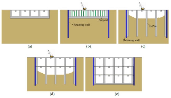
Figure 4.
Vertical extension process for existing underground spaces using the normal top-down method (from a building with one basement floor to three basement floors). The process is listed as: (a) Existing underground spaces before works; (b) Installing of earth retaining walls after reinforcing existing structure; (c) Demolition of basement Level 1 and structural frame construction (columns) after installing earth retaining walls; (d) Excavation and construction of structural frame (slabs and beams) (from B2 to B3); and (e) Completion.
3.3. Top-Down Method with MPDs [2222]
Figure 5 represents the process of vertically expanding existing underground spaces without demolishing existing structures, from the first basement level to the third basement level, using the top-down method with MPDs. To extend underground space vertically after reinforcing existing underground structure without its demolition, several pieces of equipment were placed at the top of the existing underground structure in order to install additional earth retaining walls. Therefore, prior to installation of the earth retaining walls, the supports for the structural stability of the existing slabs were installed and reinforced by considering the loads from the equipment for the earthwork (Figure 5b). To prevent the collapse of columns in the basement of the existing building during the excavation, it was necessary to install multiple posts, such as micro piles, around the columns, as shown in Figure 5c. The four micro piles installed on the outside of one column were slender, resulting in the buckling behavior. Therefore, it was necessary to tie up those to one set and connect several sets of micro piles to reduce the risk of buckling failure. Then, the foundation of the existing building was demolished, and excavation work was carried out from the bottom level of the existing building up to the extended bottom level. After completing the installation of the new foundations and columns located in the extended underground structure, as shown in Figure 5d,e, the temporary micro piles were removed.
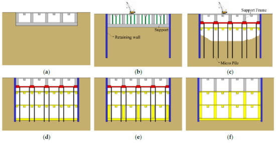
Figure 5.
Vertical extension process for existing underground spaces using the top-down method with the MPD method (from a building with one basement floor to three basement floors). The process is listed as: (a) Existing underground structure; (b) Installation of temporary supports and retaining walls; (c) Installation of temporary piles and support frames and excavation (from B2 to B3); (d) Structural frame (beams and slabs) and foundation construction; (e) Installation of columns on floors (from B3 to B2); and (f) Decomposition of temporary piles and support frames.
4. Overview of Illustrative Examples
A rectangular-shaped underground structure was used to generate illustrative examples in this paper. The effects of the shape were not considered to simplify comparative analysis of the economic impacts corresponding to sustainable vertical extension methods of existing underground spaces. The structure used for the illustrative examples has a floor plan of 74.0 × 29.6 m (Figure 6 and Figure 7), with a floor height of 3.4 m at each basement.
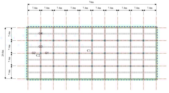
Figure 6.
Structural plan of B1 floor in the illustrative examples (unit: mm).
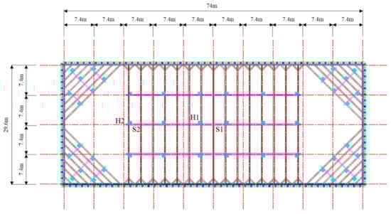
Figure 7.
Temporary struts plan in the illustrative examples for the bottom-up method (unit: mm).
To analyze the differences among the extension costs of the three sustainable vertical extension methods for underground space according to the number of basement floors of the existing building, the illustrative examples were categorized as four types: the existing building (1) without basement floors, (2) with one basement floor, (3) with two basement floors, and (4) with three basement floors. As shown Table 1, 24 illustrative examples considering sustainable vertical extension methods, the number of basement floors of the existing building (from G/L to B3), the number of extended basement floors (from B1 to B4), and structural types were generated. If there were no basement floors of the existing building before the extension, the bottom-up method and normal top-down method were applied without demolition work. If there were existing basement floors, the bottom-up method after demolishing existing underground spaces, the normal top-down method with Percussion Rotary Drill (PRD) after demolishing existing underground spaces, and the top-down with MPDs method without demolishing existing underground spaces were compared. The normal top-down method with PRD and the reverse circulation drill (RCD) and bottom-up method were not allowed to vertically extend the underground space of an existing building with more than three basement floors. Therefore, the economic impact of only the top-down with MPDs method for sustainable vertical underground extension of an existing building with three basement floors was analyzed. The structure types that the bottom-up method, normal top-down method, and top-down method with MPD analyzed were reinforced concrete (RC), steel frame, and steel frame, respectively.

Table 1.
Basic characteristics of the illustrative examples.
5. Structural Analyses of the Examples
Prior to the economic analyses of the three vertical underground extension methods, structural stabilities of the illustrative examples were checked. Structural analyses were carried out in the three illustrative examples to extend underground space vertically (from the first to third basement level) using the three sustainable methods. MIDAS Gen 2017 was used for the structural analysis by phase, including demolishment of the existing B1 floor, excavation to the B4 floor, and construction of a structural frame in the underground space.
The design of methods based on structural analysis can be roughly classified into two types. The first is to ensure the safety of the whole building when the underground structure is completed. The second is to ensure structural safety for each construction phase. In the bottom-up method, since the structural frame is constructed after the completion of the excavation to the lowest floor, the safety of the entire structure was examined after completion of construction. The frame at this time was a reinforced concrete structure.
The soil condition in all cases was assumed to be sandy soil. Therefore, the effects of changes in the ground conditions were not considered in this paper. In all the illustrative examples, temporary supports were installed at 1.5-m-wide intervals in the excavated or undemolished underground space to support the existing underground space when equipment was located on the ground floor for the newly installed retaining wall. During top-down construction, the live loads acting on first and basement floor are 20.0 kN/m2; and BF = 1.5 kN/m2, respectively, since the first floor can be used for storage space of construction materials. The load by the materials placed on the first floor disappeared after construction. The live load acting on the first floor after construction was assumed to be 5.0 kN/m2 which is higher than 3.0 kN/m2; for the basement floor. The thickness of slab was 150 mm for the bottom-up method and 200 mm for the top-down methods. The load of slab finish was 2.6kN/m2 after construction. The earth pressure of the lowest level of strut was assumed to be 300 kN/m.
The compressive strength of concrete was 24 MPa. SD500 (yield strength: 500 MPa) and SD400 (yield strength: 400 MPa) were used for a rebar with a diameter of 16 mm or more, and a rebar less than 13 mm, respectively. SM490 (tensile strength was 490 MPa) was used for steel members. Structural design and analysis were conducted according to the Korean Building Code (KBC) 2016.
In the case of construction up to three basement levels by applying three representative methods, the size and structural analysis of each member are shown in this paper. Figure 6 and Figure 7 show plans of the structural B1 floor and temporary struts planning in the illustrative examples, respectively. The size of beams and columns was determined by considering both the conditions required to serve as temporary members and structural members after the completion of the underground structure. Strut and H-pile sizes were determined in consideration of the requirements for use as temporary members. The ratio of forces to holding strength of girders (G1 to G4) and columns (C1 and C2) were checked. In the case of the bottom-up and top-down with MPD methods, the ratio of forces to holding strength of struts (S1 and S2) and H-piles (H1 and H2) also were checked. Temporary struts were installed at a depth of 2.5 m in both cases. Structural frames, such as constructed slabs and beams, prevent the side pressure of the earth retaining walls instead of temporary struts in the illustrative example using the normal top-down method. Therefore, structural analysis for the temporary struts was not necessary.
5.1. Bottom-Up Method
In bottom-up method, the beam and column were RC structures. The sizes of the members for Case #5 used in the vertical underground extension using the bottom-up method are described in Table 2. Sections and reinforcement details of typical girders after construction are shown in Figure 8. They were the same for each construction phase. Figure 9 shows the moment diagram of RC frame structure after the completion of construction. As the result of the structural analysis, the forces acting on the designated members of them are represented in Table 2 as a ratio to the holding strengths. In case of the bottom-up method, the conventional reinforced concrete frame system was used as structural systems after completion of excavation. The forces acting on girders of ground floor (1F) were higher than those of the basement floor (BF) because live load on 1F was higher than that on BF. Highest values were found in the main girders (G3 and G4) which were connected beams and the ratio of forces to holding strengths reached 0.95. From this, the members were shown to be optimally designed. The axial force ratios of columns C1 and C2 were 0.42 and 0.43 after construction, respectively. The strut S1 had an axial force ratio of 0.66 during construction. Consequently, it can be seen that the structural member was designed to be safe enough for the applied load.
Table 2.
Member sizes and analyzed force ratios of structural members in the illustrative example using the bottom-up method (Conventional RC construction, Case #5).
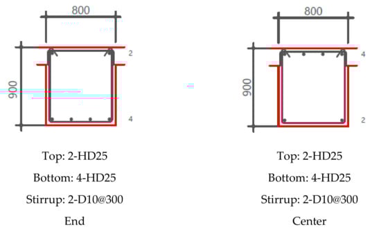
Figure 8.
Detail of RC girders after the completion of construction.
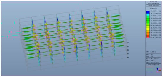
Figure 9.
Moment diagram of RC frame structure after the completion of construction.
5.2. Normal Top-Down Method
In the illustrative example using the normal top-down method, steel girders and SRC columns were used. The sizes of the used girder and column members of Case #6 are shown in Table 3. As mentioned previously, the first floor can be used for storage space of construction materials. Therefore, the force ratios during construction was higher than those after completion of construction. The moment ratio of girders reached 0.94 and 0.96 at G2 and G4, respectively, during construction. However, they were reduced to 0.42 and 0.44 after construction, respectively. The force ratios of girders of BF increased after completion of construction since the live load increased from 1.5 kN/m2 to 3.0 kN/m2. The moment ratios of G2 and G4 were 0.95 and 0.89 after completion of construction, respectively. For columns, the ratio reached up to 0.67 for C2 during construction, but it was reduced to 0.15 after construction. For the results, all cases were structurally stable and the member were designed optimally.
Table 3.
Moment size and analyzed force ratios of structural members in the illustrative example using the normal top-down method (Case #6).
5.3. Top-Down with MPD Method
For the bottom-up method, the column was installed between MPDs in RC structure while the beam was a steel structure like for the normal top-down method. In the illustrative example of the case 14 using the top-down method with MPDs, the size of the supporting frames used was H-300 × 300 × 10 × 15 mm and micro piles were installed around the existing columns in the basement. The sizes of the girders and columns used were 800 × 900 mm and 900 × 900 mm, respectively. Table 4 shows the force ratio of each member in the example in which the top-down with the MPD method was applied for vertical underground extension. The high moment ratios of 0.96 and 0.89 were found at G2 and G4, respectively. The shear force ratios of girders were not larger than 0.15. The axial fore ratios of MPDs reached 0.75 and 0.81 during construction while those of column to 0.36 and 0.37 after construction. The illustrative example using the top-down method with MPDs was structurally stable, because the force ratios of all structure members were less than 1.0. According to the structural analysis results in the illustrative examples to which the three vertical underground extension methods were applied, all cases were structurally stable.
Table 4.
Member size and analyzed force ratios of structural members in the illustrative example using the top-down with the MPD method (Case #14).
6. Economic Impacts
The extension costs of each illustrative example were calculated based on the expected amount of used and demolished materials. Table 5 represents the detailed extension cost of the case # 16. The calculated vertical underground extension cost consisted of material and labor costs. Material costs were classified as reinforcement, demolition, earthworks, structural frame construction, and finishing costs. Materials for the reinforcement work included support (EA), additional reinforcement member (m3), MPD posts (boring: m, H-pile: ton), beams for MPD (H-pile: ton), etc. in the paper. Earthworks were related with retaining walls (CIP), PRD (D800: m), excavation, temporary struts, and so on. Structural frames were mainly composed of slabs, beams, columns, exterior walls, and foundations. To calculate materials cost of each structural member, form (m2), concrete (m3), support (m2), reinforced bar (ton), and deck plate (m2) were considered.
Table 5.
Detailed construction costs of Case #16.
Table 6 represents the sustainable vertical underground extension costs of the 24 illustrative examples. Unlike other methods, the top-down with MPD method includes reinforcement costs and does not include demolition costs. Also, the sustainable vertical underground extension cost of an existing building without a basement floor does not include demolition costs. Figure 10 shows the sustainable vertical underground extension cost per extended floor considering the number of basement floors of an existing building (G/L to B3) and the number of extended basement floors (one to four floor extension). In the illustrative examples, to vertically extend the underground space of an existing building without a basement floor, the extension costs using the bottom-up and the normal top-down methods were compared. It is difficult for the bottom-up and the normal top-down methods with PRD and RCD to vertically extend the underground space of an existing building with more than three basement floors. Therefore, they were not included when analyzing and comparing the economic impacts of vertical underground extension methods. In all examples using the three methods, the larger the number of basement floors of existing buildings, the greater the cost per extended basement floor. The larger the number of basement floors of existing buildings, the higher the cost of demolition and reinforcement works. In particular, the cost of demolition work was strongly related to the number of basement floors of existing buildings. Also, the larger the number of vertically extended basement floors, the dramatically less the extension cost per extended floor in all examples.
Table 6.
Extension costs of underground vertical extension methods in the 24 illustrative examples.
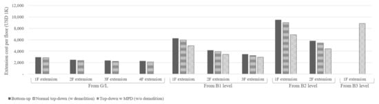
Figure 10.
Extension cost per floor considering the number of existing basement floors (G/L to B3) and vertically extended basement floors (B1F to B4F extension).
As the results, the top-down with MPD method showed the lowest extension cost per extended basement floor under the same conditions, followed by the normal top-down and the bottom-up methods. In particular, the vertical extension cost using the top-down with MPD method, for two basement floor extensions of the existing building with two basement floors, was approximately 76% of that using the bottom-up method. As the number of vertically extended basement floors increased, the difference between extension costs of the underground extension methods decreased. Unlike the bottom-up method, the normal top-down method had relatively low extension costs for earthworks and structural framing for temporary columns, support frames, and so on. The demolition cost for the vertical underground extension using the top-down with MPD method was lower than those of other two methods, but the cost of reinforcement work was additionally considered unlike other methods due to the additional MPD installation. Also, the cost of reinforcement work was less than that of demolition work. For vertical underground extension of an existing building with the same number of basement floors, the extension cost per extended basement floor decreased as the number of extended basement floors increased. For example, the costs per basement floor for vertically extending two and three basement floors of an existing building with one basement floor were 68% and 57% of that for extending one basement floor, respectively.
Earthwork cost of the top-down with MPD method was the lowest, followed by the normal top-down and bottom-up methods. The difference in earthwork costs for the bottom-up and top-down methods was related to the cost for installing temporary struts. The normal top-down method additionally considered PRD to calculate the earthwork cost, unlike the top-down with MPD method, while the excavation cost of the top-down with MPD method was lower than those of other methods. Cost of structural frames of the top-down with MPD method was also the lowest, followed by the normal top-down and bottom-up methods. Although cost for foundations of each method was the same, cost for columns and exterior walls of the top-down with MPD method was lower than those of other methods. The amount of newly constructed columns and exterior walls of the top-down with MPD method was smaller than those of other two methods due to absence of demolition works. In particular, for the normal top-down methods, H-piles were used for reinforcing existing columns.
7. Discussion and Conclusions
This paper analyzed the economic impacts of three vertical extension methods for basement floors of existing buildings, which were the bottom-up, normal top-down, and top-down with MPDs methods. Extension cost of the three methods to sustainably expand underground spaces of existing buildings were calculated based on the quantity of used or demolished materials, their unit cost, and the assumed labor cost rate. A process to select an appropriate vertical underground extension method among them was also proposed by considering construction site conditions, such as the number of existing basement floors of buildings and extended basement floors, and whether demolition work is required. The top-down method with MPDs can vertically extend the underground space using micro piles and temporary support frames without demolishing the existing basement floors of buildings, unlike other extension methods that need to demolish the existing underground structure. Micro piles and temporary support frames were used as reinforcement elements for existing and extended underground space and retaining walls.
Based on the three construction methods, the number of basement floors in existing buildings, and the number of extended basement floors, the economic impacts were analyzed by calculating and comparing the underground vertical expansion costs of 24 illustrative examples. When an underground space of the existing one or two basement floors exists, from the cost-oriented perspective, the existing underground structure should be appropriately reinforced by using micro piles, and then two or more layers should be expanded by using the underground expansion method. This might be beneficially coordinated according to the characteristics of projects. In addition, when an underground space of the existing three basement floors exists, the construction cost is estimated to be significant, because the area to be enlarged when the underground vertical extension is constructed at the underground fourth floor is relatively small. In other words, the higher the number of underground floors of existing buildings and the greater the number of underground vertical expansions, the more economically advantageous the top-down with MPDs method is.
Financial analysis does not guarantee the structural stabilities of buildings with underground spaces extended by using these construction methods. Therefore, practitioners should simultaneously consider various issues, such as existing soil and bearing capacity of existing buildings, relevant building regulation or codes, and policies. For example, because of soil conditions on sites, it can be difficult to apply top-down methods or install MPD for support existing underground structures, which are relatively more slender than other types of piles.
The proposed extension processes through considering their structural stabilities and economic impacts help practitioners to select appropriate construction techniques and reduce costs and risks. They will provide opportunities to sustainably and efficiently expand underground space of existing buildings in congested urban areas without dismantling whole buildings. Consequently, it is expected that the amount of the construction and demolition (C&D) waste generated during the demolition phase of existing buildings and the construction phase of new buildings will be reduced. However, the proposed process was not yet applied to actual projects. Therefore, in the future, the strengths and weaknesses of the proposed process will be analyzed based on the implementation of sustainable underground vertical extension methods on actual sites.
Author Contributions
S.-y.S. made substantial contributions to conceptualization of the study, acquisition, analysis, and drafting and revising the article; B.L. helped to collect relevant data and analyze the result; J.W. proposed the research methodology and reviewed and edited the manuscript. All authors have read and agreed to the published version of the manuscript.
Acknowledgments
This work is supported by the Korea Agency for Infrastructure Technology Advancement (KAIA) grant funded by the Ministry of Land, Infrastructure and Transport (Grant No. 18EREP B099826-04).
Conflicts of Interest
The authors declare no conflict of interest.
References
- Jung, S.J.; Kim, S.-K.; Seo, S.Y. Structural safety of the building constructed by top-down method corresponding to earth pressure distribution and floor system. J. Archit. Inst. Korea Plan Des. 2017, 33, 3–10. [Google Scholar]
- Volchko, Y.; Norrman, J.; Ericsson, L.O.; Nilsson, K.L.; Markstedt, A.; Öberg, M.; Mossmark, F.; Bobylev, N.; Tengborg, P. Subsurface planning: Towards a common understanding of the subsurface as a multifunctional resource. Land Use Policy 2020, 90, 104316. [Google Scholar] [CrossRef]
- Volchko, Y.; Norrman, J.; Ericsson, L.O.; Nilsson, K.L.; Markstedt, A.; Öberg, M.; Mossmark, F.; Bobylev, N. Underground space as an urban indicator: Measuring use of sub- surface. Tunn. Undergr. Sp. Tech. 2016, 55, 40–51. [Google Scholar]
- Bobylev, N. Comparative analysis of environmental impacts of selected underground construction technologies using the analytic network process. Autom. Constr. 2011, 20, 1030–1040. [Google Scholar] [CrossRef]
- Chen, Z.; Su, L.; Zhang, C. Research on the Synergy Degree of Aboveground and Underground Space along Urban Rail Transit from the Perspective of Urban Sustainable Development. Sustainability 2016, 8, 934. [Google Scholar] [CrossRef]
- Bobylev, N. Mainstreaming sustainable development into a city’s Master plan: A case of Urban Underground Space use. Land Use Policy 2009, 26, 1128–1137. [Google Scholar] [CrossRef]
- Yang, X.; Chen, Z.; Cai, H.; Ma, L. A Framework for Assessment of the Influence of China’s Urban Underground Space Developments on the Urban Microclimate. Sustainability 2014, 6, 8536–8566. [Google Scholar] [CrossRef]
- Ro, Y.-C.; Lee, C.-S. Selection of retaining wall system for underground parking lots expansion of apartments. J. Korea Inst. Constr. Eng. Manag. 2008, 9, 99–107. [Google Scholar]
- Kim, K.M.; Rhim, H.C.; Lee, K.J. Development of Underground Space Underneath Existing Buildings. In Proceedings of the 2010 Conference of Architectural Institute of Korea, Seoul, Korea, 20–23 October 2010; Architectural Institute of Korea: Cheongju, Korea, 2010; pp. 153–154. [Google Scholar]
- Bing, C. Floating underground extension method—Remodeling case 2. Remodeling 2012, 46, 13–20. [Google Scholar]
- Jang, D.; Park, D.; Kim, Y.; Lim, H. Research on the Development of FUSEM Method for Seoul City Main Hall. In Proceedings of the Conference of Architectural Institute of Korea, Gwangju, Korea, 22–25 October 2012; Architectural Institute of Korea: Gwangju, Korea, 2010; pp. 513–514. [Google Scholar]
- Lee, J.; Bing, C. Remodeling case—Chungdam Chunggu Apartment. Build. Construct. 2012, 42–51. [Google Scholar]
- Kim, T.H.; Bang, J.S.; Lim, C.W. A Study on the Basement Extension Construction Method Using Existing Piles. In Proceedings of the 2014 Conference of Architectural Institute of Korea, Seoul, Korea, 25 April 2014; Architectural Institute of Korea: Seoul, Korea, 2014; pp. 407–408. [Google Scholar]
- Park, D.-S.; Lew, Y.-K.; Choi, K.; Lee, J. Introduction of floating underground space extension method (FUSEM) for preservation and continuous utilization of old Seoul city hall. J. Korea Concr. Inst. 2013, 25, 44–48. [Google Scholar]
- Kim, S.K.; Lee, J.E.; Kim, T.W.; Koo, J.M.; Jung, S.; Seo, S.Y. Construction Technology and Structural Safety Assessment for Expansion of Underground Parking Lot of Apartment Complex. In Proceedings of the 2016 Conference of Architectural Institute of Korea, Architecutral Institute of Korea, Busan, Korea, 4–6 October 2016; pp. 1471–1472. [Google Scholar]
- Jung, S.J.; Kim, J.H.; Lee, B.H.; Hwang, K.S.; Seo, S.Y. Establishment of a Technology for Earthwork Safety at New Construction/Extension of Underground Parking Lot in Building. In Proceedings of the 2018 Conference of Korea Concrete Institute, Korea Concrete Institute, Changwon, Korea, 1 May 2018; pp. 797–798. [Google Scholar]
- Attar, A.; Boudjakdji, M.A.; Bhuiyan, N.; Grine, K.; Kenai, S.; Aoubed, A. Integrating numerical tools in underground construction process. Eng. Constr. Arch. Manag. 2009, 16, 376–391. [Google Scholar] [CrossRef]
- Ha, T.; Lee, S. Advanced Construction Stage Analysis of High-Rise Building Considering Creep and Shrinkage of Concrete. In Proceedings of the 2013 World Congress on Advances in Structural Engineering and Mechanics (ASEM13), Jeju, Korea, 8–12 September 2013; International Association of Structural Engineering and Mechanics: Jeju, Korea, 2013; pp. 2139–2147. [Google Scholar]
- Seo, S.; Lee, R.; Construction, S.H. Permanent Earth Retaining Composite Frames for Constructing Underground Structure. In Proceedings of the Conference of Architecutal Institute of Korea, Seoul, Korea, 24–25 October 2005; Architectural Institute of Korea: Jecheon, Korea, 2005; pp. 41–68. [Google Scholar]
- Thompson, J.; Zadoorian, C. A Case Study for Top-Down and Construction Methodology for a High-Rise Development in Los Angeles, California. In Proceedings of the SEAOC Convention, Big Island, HI, USA, 23–27 September 2008; SEAOC: Sacramento, CA, USA, 2008; pp. 1–8. [Google Scholar]
- Archidata Design. Eart Retaining Wall. Available online: http://www.archidata.co.kr/NewWin/NewWin.asp?VT=Design&selID=54599&ddcodeid=2291 (accessed on 9 January 2020).
- Ha, S.; Choi, C.; Park, M.; Hwang, K.; Lee, L. Development of New Construction Method of ESD and BRD. In Proceedings of the Conference of Archietctural Institute of Korea, Jecheon, Korea, 24–25 October 2005; Architectural Institute of Korea: Jecheon, Korea, 2005; pp. 305–308. [Google Scholar]


© 2020 by the authors. Licensee MDPI, Basel, Switzerland. This article is an open access article distributed under the terms and conditions of the Creative Commons Attribution (CC BY) license (http://creativecommons.org/licenses/by/4.0/).