1. Introduction
Technological advance in the field of materials development allows engineers to select materials depending on their structure mechanics [
1]. Nowadays, there are many options for selecting materials. However, from the structure effort’s point of view engineers use a few basic selection criteria. The criteria are as follows:
a weight criterion;
a safety and reliability criterion;
a technology-oriented criterion;
an ergonomics and an aesthetics criterion; and
an environmental criterion [
2,
3,
4,
5,
6].
Depending on the intended use, sometimes the safety criterion is more significant and in some cases the weight criterion plays a more important role. Regardless of the structure to be developed, all the above-mentioned criteria are of utmost importance [
7,
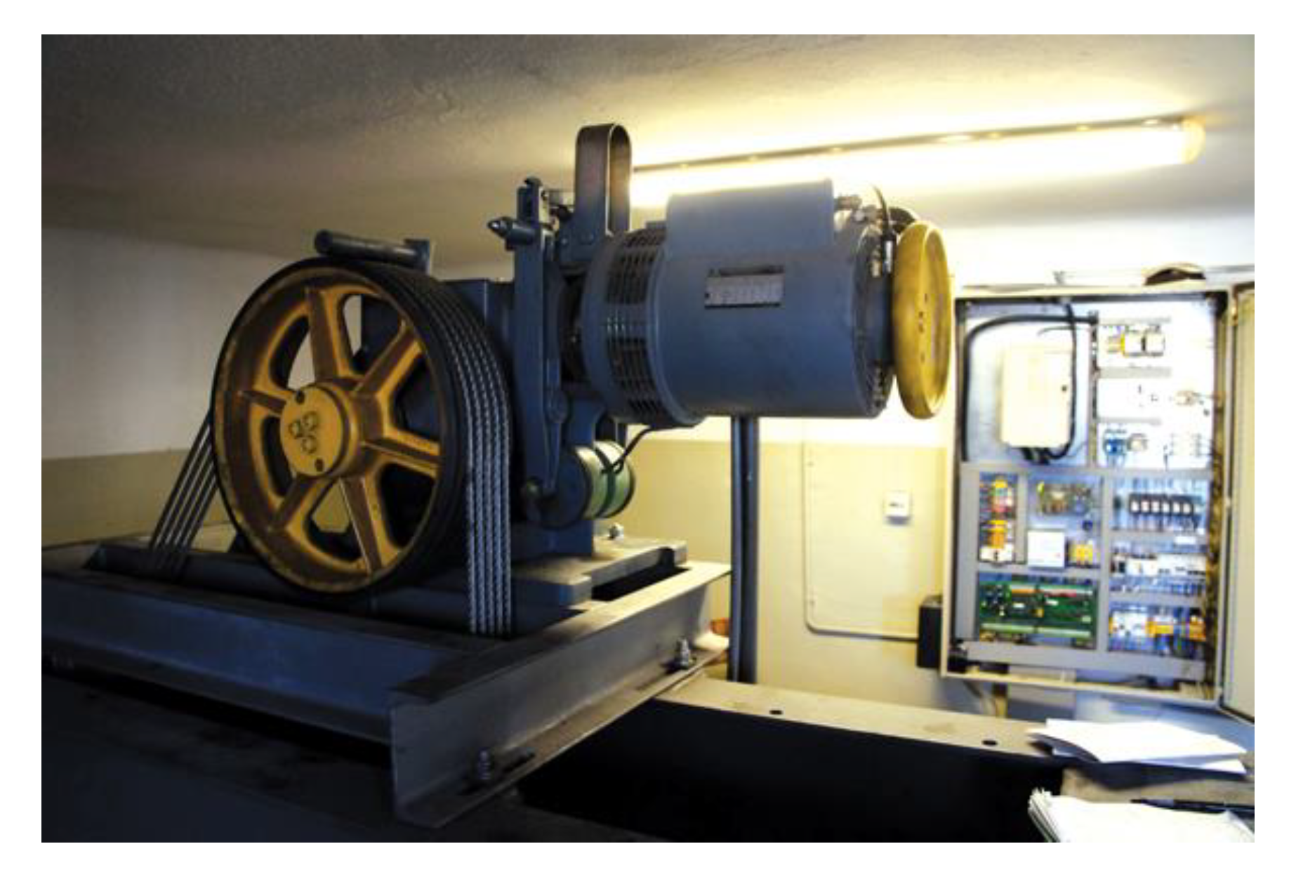
8]. This refers not only to devices operated directly in the industry but also to lifting and handling machines and devices. Materials handling machines belong to this type of equipment and are commonly called elevators. Their complexity level grows rapidly in the remaining mechanical sectors of industry. Structure optimization, a downsizing method, and semi-products manufacture are current development trends in the lifting sector of industry. Due to high financial outlays spent on searching for new engineering solutions, the heavy and welded carrying structures used so far are replaced with light and bolted structures where the welding processes are reduced to a minimum. The carrying frame of the power unit, where a reducer assembly equipped with a drive motor is installed, is the main carrying structure in passenger lifts. It is subject to loads not only when the cabin is in motion but also when the lift stops. An example of the carrying frame is presented in
Figure 1.
Until now, the carrying frames have been made from hot-rolled profiles of type C and 2T, joined by means of welding technology. High stiffness is a significant advantage of such structures due to the way they are manufactured [
9]. However, the manufacturing process is too long and the total frame weight exceeds the installation capabilities of a team. Additional equipment, such as hoists, are often necessary. The fact that this solution lacks versatility is another significant disadvantage. If the position of the power unit in relation to the frame must be modified, it is necessary to perform time consuming work, such as cutting the welded profiles, mechanical cleaning, and re-welding. To fulfil the weight and technology-related criteria and to pursue the manufacturing processes developments the carrying frames in the form of cold-rolled profiles have been introduced. The profiles are pre-prepared by using laser cutting technology. This technology used in the preparation of frame semi-products significantly decreases the time of installation, which is reduced to the welding processes, kept to minimum by replacing them with separable assembling by means of bolts. The structure versatility in terms of changes resulting from the lifting mechanism configuration, e.g., carrying ropes spacing, is an advantage of this solution, as is fast installation and its significantly lower unladen weight. Moreover, it is possible to transport the structure in pieces to the place of installation. Thus, it is not necessary to use any additional transportation equipment. A disadvantage of such an approach to the structure is the need to make additional calculations of the structural effort due to the presence of loads, which requires knowledge of the highly precise scheme of loads. The application of finite element method (FEM) analysis is described in publications in many scientific areas. In [
10], the authors described the application of the FEM method to the analysis of the aircraft suspension. The results obtained from experimental studies were comparable to the results obtained from the numerical analysis. In [
11] the authors focused on optimising the frame with regard to its weight. They offered optimized profiles in terms of dimensions while maintaining the appropriate value of slips. In addition, the FEM method is used to determine torsional flexural buckling in steel columns, expanded in [
12], and to analyse the braking system of the friction crane described in [
13]. The authors in [
14,
15] present the operation of safety gears as a result of changing operating conditions and based on experimental studies carried out wavelet analysis of the results obtained. Apart from the above-mentioned articles describing the FEM simulation method, literature contains publications about such methods as the discrete element method (DEM) described, inter alia, in [
16,
17], general particle dynamics (GPD) presented in [
16,
17,
18], or peridynamics discussed in [
19,
20,
21,
22,
23,
24,
25,
26,
27].
2. A numerical Model of the Carrying Structure Versus a True Model
Both existing and new structures are designed by applying modern design methods based on three-dimensional modelling. The literature proves that the finite element method can be used for many applications. It is adopted to design the carrying frames for the motor vehicles [
28] and to analyse the stiffness of the carrying structures in numerically-controlled machines [
29]. Furthermore, it is applied to examine the impact of the lift braking force on the deformation of a plastic guide [
30,
31] or subcritical conditions of clamped thin-walled profiles [
32]. It is also used in many other sectors of industry connected with modelling the effort aspects [
33,
34,
35,
36]. As for bolted structures, there is an additional advantage of this approach. It is possible to perform virtual installation with which an engineer can prepare a qualitative assessment of the design. Additionally, the structure can be evaluated in terms of compliance with respective installation stages in the manufacturing and installation conditions. The load presence at a certain distance from restraint is a frequent case of structure effort. The load support through the stiffness of such subassemblies, e.g., a motor, on the shaft of which a wheel is located, is a quite common model of the structure [
37,
38,
39]. The applicable model is presented in
Figure 2 and
Figure 3. It refers to the carrying frame of the friction lift power unit.
Currently, the solution of the carrying frame presented in
Figure 1 is not profitable from the economic point of view due to long-lasting manufacturing process and the lack of versatility. The bent structures are an alternative to the welded ones. They are bolted in order to reduce the welding processes to a minimum; see
Figure 3.
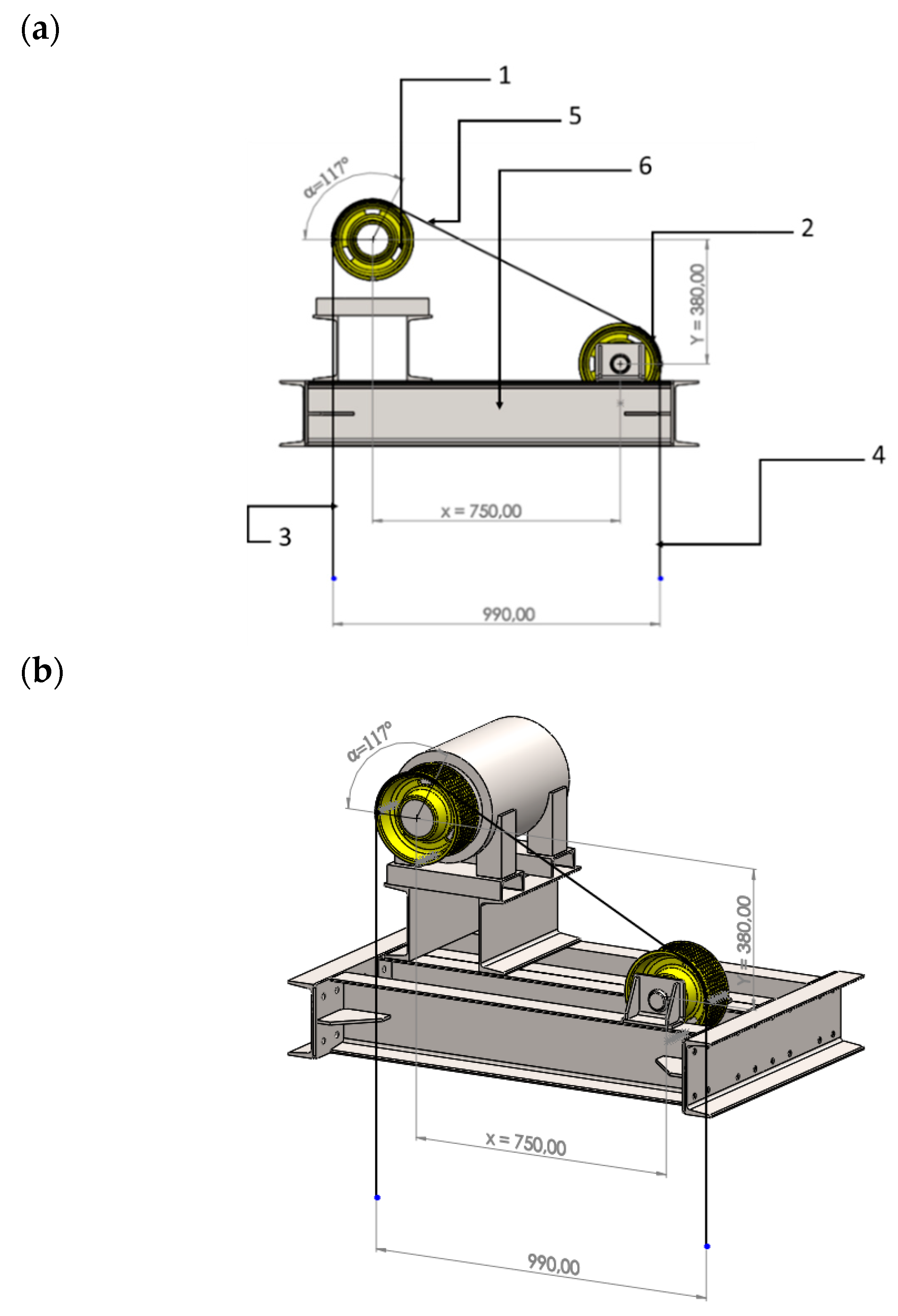
A three-dimensional model of the friction lift carrying structure with the geometry of the carrying ropes system in
Figure 4, while diagram of the friction lift structure is presented in
Figure 5.
The general method of loading the crane frame can be expressed using the Euler equation:
where:
: Force on the cab side
: force on the counterbalance side
μ: friction coefficient between the ropes and the friction wheel
α: friction wheel wrap angle with ropes
Therefore, T
1 and T
2 forces that load the frame system andcome from changeable operating conditions and they are related to the quantity of passengers in the elevator cabin. Numerical analysis of the carrying frame derives from determining the most detrimental layout of the loads due to T
1 and T
2 forces in the working conditions described in the standard. As appropriate, the values of T
1 and T
2 forces are expressed with the following mathematical dependencies taking into consideration the provisions of PN EN 81.20 standard [
40]:
Case I: Applying the load that equals 125% of the nominal load capacity to the cabin in the bottom position.
• the force of tension in the ropes on the cabin side:
• the tension force of the ropes on the counterweight side:
Case II: The cabin is blocked (the counterweight rests on the fenders), the empty cabin is in the highest top position, the power unit lifts the cabin up.
• the tension force of the ropes on the cabin side:
• the tension force of the ropes on the counterweight side:
Case III: Emergency braking when driving downwards with the nominal load capacity, the cabin is in the bottom position.
• the force of tension in the ropes on the cabin side:
• the tension force of the ropes on the counterweight side:
Case IV: Emergency braking when driving upwards with an empty cabin, the cabin is in a top position.
• the tension force of the ropes on the cabin side:
• the tension force of the ropes on the counterweight side:
Optimization analysis of the carrying frame structure assumed the following input data, resulting from the operation of an elevator with the nominal load capacity of 1000 kg, presented in
Table 1 below.
Indices describing the values of T forces in respective cases stand for: the first digit refers to force on the friction wheel side, the second digit refers to the examined case. Basing on the assumed weight conditions described in
Table 1 and equations determined on the basis of the PN EN 81.20 standard [
40], the values of forces which load the frame system are compiled in
Table 2.
Based on the obtained values of forces a numerical model of the frame was prepared and was subject to numerical calculations in the assumed load conditions focusing on the structure effort.
3. Remote Load
A fixed remote load simulates the impact of load located at a certain distance from attachment excluding the elements placed between the load and restraint. Another example of remote load is the load at a certain distance from restraint without any additional subassemblies between them [
41]. A schematic diagram of remote load is presented in
Figure 6.
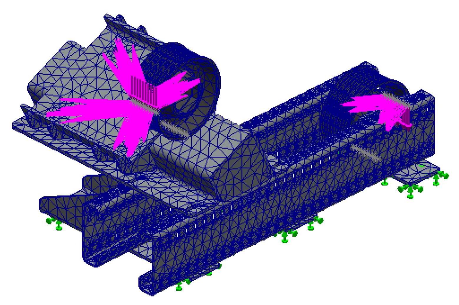
Concentrated force, weight, bending or torque moment can be a remote load. The remote load subject to the analysis is connected with a design model by means of a link. The link plane and the load application point are indicated. A virtual stiff rod is formed between two indicated elements of the link and joins the restraint plane with the load application point. With respect to the above definition of remote load and the examined cases of carrying frames load, the applied method of the numerical model load reflects the real load conditions to the greatest extent.
4. Boundary Conditions in the Previous Version
The frame structure is loaded by the ropes belting a friction wheel and by a rope directional wheel. The friction wheel is mounted on the power unit shaft. It is a complicated process to model such a complex system consisting of a motor with the gearless transmission system. The complexity of the power unit design practically prevents the studies from analysing it by the FEM method. Thus, in order to reflect the load transfer onto the frame structure in the place where the power unit is mounted to the frame, the remote load was applied. The first boundary condition in the analysed case was to define the frame restraint in relation to the existing structure, to which the frame, toghether with the assembly, should be mounted in reality. For that purpose, fixed restraint was selected from those available. It receives all six degrees of freedom. Displacements and rotations in the successive directions are: Ux = 0, Uy = 0, Uz = 0, and Rx = 0, Ry = 0, Rz = 0, respectively. The next step was to define the load. In the presented case it is a direct transfer of the load applied on the ropes.
The grid with 35 mm size element and 1.75 mm tolerance for the element size was used to make calculations so was the iterative mode solver, which allowed the automatic creation of the FEM grid; see
Figure 8.
The values of rope load forces T1 and T2 were applied to the tangent created by the rope groove outline and the force direction, which was presented in
Figure 9. The value of respective loads come from the quotients of the force value for a given case and the number of the carrying ropes (n = 10). As the remote load was used in simulation, the set load value for particular cases was transferred directly to the restraint of wheels on the frame. Such a load model affects directly the frame structure by forces acting on the lift ropes. The numerical calculations of stresses and displacements were made basing on the assumed boundary conditions and the load for the 1st case. The results of these calculations are presented in
Figure 10.
The results of numerical calculations for the maximum values of nodular stresses and displacements for the remaining cases are presented in
Table 3.
Basing on the numerical calculations, it can be noticed that when the cabin is loaded with 125% of the nominal load capacity and it is in the maximum bottom location, this adversely affects the values of stresses and displacements to the greatest extent. The highest values of stresses and displacements result from the additional load affecting the frame generated by the carrying ropes weight. Moreover, the attention should be paid to the place where the maximum stresses appear. They are generated around the holes that fix the power unit and which are closer to the friction wheel (the red field in
Figure 10). The location of these values is connected with the application of the remote load to the frame structure and its stiffness in the transition area between the power unit and the friction wheel.
5. Manufacturing Time of the Existing Solution
Basing on the above analysed model of the frame it can be noticed that it is made of hot-rolled profiles of type C with the side of 180 mm which are welded with the modular sheet metal and the rib type structural elements. Steel materials, grade S235, for which yield strength Re is 235 MPa and the Poisson’s ratio v is 0.3, were used in production of frames. Working time needed to prepare such a design solution can be split into the following elements:
Time of hot-rolled profiles cutting: tcp = 30 min.
Time of nodular sheet metals laser cutting: tpbw = 3 min.
Time of ribs laser cutting: tpz = 2 min.
Time of structure welding: ts = 30 min.
Time of structure bolting: tsk = 10 min.
Preparation time: tp = 10 min.
Total time t
c necessary to prepare the welded structure is a function of respective times of detail parts preparation and it can be expressed with the following formula:
Based on the presented values the time needed to prepare the frame in the welded version is 85 min with a weight of 160 kg. Furthermore, the lack of versatility of this solution should be taken into account. Thus, it is impossible to change the spacing between the carrying ropes, if such a need arises. The frame weight is also a significant aspect. As far as the transport to hard-to-reach places is concerned the additional equipment like transportation cranes is required.
6. Optimization of the Carrying System Structure
The purpose of optimization of the existing solution is to obtain versatility in terms of easiness in changing the spacing of the carrying ropes and of the weight criterion with the structure strength criterion maintained with respect to the most adverse load case. For that purpose, the numerical model of the carrying frame was prepared, on the assumption that the frame would be made from elements cut with laser technology and profiled on the press brake. The frame model presented in
Figure 2 was developed to change quickly the carrying ropes spacing by dismantling fasteners, positioning detail parts and re-assembling elements. The welding process in this solution was limited to a minimum.
7. Boundary Conditions in the New Version
The boundary conditions connected with the load of the optimized frame system are convergent to the existing model as far as the value and the direction of load are concerned. The frame restraint in relation to the existing structure was defined as motionless on the surfaces of the frame elements, which is presented in
Figure 11.
For that purpose,
motionless restraint was chosen. This type of restraint receives all six degrees of freedom. Displacements and rotations in the respective directions are the following: U
x = 0, U
y = 0, U
z = 0 and R
x = 0, R
y = 0, R
z = 0. It was symbolized with green arrowheads, which take away all degrees of freedom from the modelled system. The grid with 35 mm sized element and with 1.75 mm tolerance of the element size was chosen for calculations. The solver, working in an iterative mode, was selected to make calculations, which allowed the researchers to use an automatic mode to create the FEM grid; see
Figure 12.
Numerical calculations of stresses and displacements were made basing on the accepted boundary conditions and the load for the 1st case. The calculations results are presented in
Figure 13.
The results of numerical calculations with the maximum values of nodular stresses and displacements for the remaining cases are presented in
Table 4.
Additionally, in the optimized solution of the carrying frame the 1st case is the most adverse in terms of load. The maximum value of nodular stresses is 307 MPa and the maximum displacement increase is 0.977 mm. The reason for the highest value of stresses in this case is the same as for the design frame prior to optimization. The only difference is the fact that the successive values are lower comparing to the respective cases.
8. Manufacturing Time of the New Solution
Basing on the optimized model of the frame, it can be noticed that most detail parts are modelled as the laser cut elements and then they are subject to the cold forming process. Working time needed to prepare such a design solution can be split into the following elements:
Time of laser cutting: tl = 23 min.
Time of cold forming: tg = 15 min.
Time of structure welding: ts = 15 min.
Time of structure bolting: tsk = 10 min.
Preparation time: tp = 10 min.
Total time t
c necessary to prepare the welded structure is a function of respective times of detail parts preparation and it can be expressed with the following formula:
Basing on the presented values the time necessary to prepare the frame in the bolted version is 73 min with 111.6 kg weight of the frame. In the presented optimized solution, the attention should be paid to the fact that it is possible to quickly modify the position of detail parts in relation to each other and to adjust the carrying ropes spacing. Apart from versatility the weight saving is a significant advantage. In consequence, the cost of materials is lower.
9. Discussion of the Simulation Results
Having verified the results received after the numerical analyses it can be noticed that in the first solution the values of stresses are on a higher level, comparing to the optimized case. The reason for that is the fact that in the first case the reaction resultant loads the mounting system of the power unit unfavourably, see
Figure 14a. Similarly, the location of the load reaction in the frame optimized model is presented in
Figure 14b. By analysing the method of loading it can be noticed that in the second case the reaction acts in the direction of the height of a profile that fixes the power unit. This has more favorable impact on the value of stresses in the entire structure.
One more advantage of three-dimensional modelling and numerical simulation is the possibility to perform virtual installation, to adjust the solution versatility range and to find the most optimal solution for the manufacturing time reduction. It should be noticed that welding processes are time-consuming and expensive. Thus, in this particular case it would be difficult to fulfil an economic criterion. The structure optimization in relation to economic aspects has significant impact on total investment-related costs. This was evidenced using the example of the times needed to perform respective operations. The results of the frames weight reduction in both cases and the installation time reduction are presented in
Figure 15.
It is worth noticing that the time needed to prepare the optimized case is 12 min shorter and the dead load of the optimized solution is 48 kg lower than the case prior to optimization, thus, lower by 14% and 30%, respectively. The way that manufacturing processes are organized plays a significant role both in meeting the economic and weight criteria as well as in terms of the manufacturing process efficiency and final installation where errors are reduced to a minimum.
10. Conclusions
The analysis of the simulation results allows for the formulation of the following final conclusions:
The use of distant loads loading the crane support frame allows reliable results of the simulation to be obtained.
Thanks to the finite element method, it is possible to limit costly productive processes directly affecting the final cost of the product.
The use of the FEM method in the discussed case allows to reduce the time and costs of prototyping new, improved constructions.
The use of numerical methods in the discussed cases allowed the structure to be optimized in terms of reduction of assembly time by 14%, compared to the structure before optimization.
The presented solution after the optimization process has a lower weight by 48% compared to the solution before optimization, which directly reduces the cost of implementation.
Author Contributions
All authors contributed to the study conception and design; methodology: P.L., K.P., T.K., H.R.; formal analysis and investigation: P.L., K.P., T.K.; writing—original draft preparation: P.L., K.P., H.R.; writing—review and editing: P.L., T.K., H.R.; funding acquisition: P.L., K.P., T.K., H.R. All authors have read and agreed to the published version of the manuscript.
Funding
The project/article was financed in the framework of the project Lublin University of Technology-Regional Excellence Initiative, funded by the Polish Ministry of Science and Higher Education (contract no. 030/RID/2018/19).
Conflicts of Interest
The authors declare no conflict of interest.
References
- Fuertes, J.P.; Luis, C.J.; Luri, R.; Salcedo, D.; León, J.; Puertas, I. Design, simulation and manufacturing of a connecting rod from ultra-fine grained material and isothermal forging. J. Manuf. Process. 2016, 21, 56–68. [Google Scholar] [CrossRef]
- Przystupa, K. Selected methods for improving power reliability. Przegląd Elektrotechniczny 2018, 94, 270–273. [Google Scholar] [CrossRef]
- Przystupa, K. Reliability assessment method of device under incomplete observation of failure. In Proceedings of the 2018 18th International Conference on Mechatronics-Mechatronika (ME), Brno, Czech Republic, 5–7 December 2018; pp. 1–6. [Google Scholar]
- Przystupa, K. The methods analysis of hazards and product defects in food processing. Czech J. Food Sci. 2019, 37, 44–50. [Google Scholar] [CrossRef]
- Pieniak, D.; Walczak, A.; Niewczas, A.M.; Przystupa, K. The effect of thermocycling on surface layer properties of light cured polymer matrix ceramic composites (PMCCs) used in sliding friction pair. Materials 2019, 12, 2776. [Google Scholar] [CrossRef] [PubMed]
- Yeromenko, V.; Kochan, O. The conditional least squares method for thermocouples error modeling. In Proceedings of the 2013 IEEE 7th International Conference on Intelligent Data Acquisition and Advanced Computing Systems (IDAACS), Berlin, Germany, 12–14 September 2013; Volume 1, pp. 157–162. [Google Scholar]
- Andrzejczak, K.; Młyńczak, M.; Selech, J. Poisson-distributed failures in the predicting of the cost of corrective maintenance. Eksploat. Niezawodn. Maint. Reliab. 2018, 20, 602–609. [Google Scholar] [CrossRef]
- Selech, J.; Andrzejczak, K. An aggregate criterion for selecting a distribution for times to failure of components of rail vehicles. Eksploat. Niezawodn. Maint. Reliab. 2020, 22, 102–111. [Google Scholar] [CrossRef]
- Wang, X.; Dong, S.L.; Wan, H.Y. Finite element analysis of welded spherical joints’ stiffness. Zhejiang Daxue Xuebao Gongxue Ban J. Zhejiang Univ. Eng. Sci. China 2000, 34, 77–82. [Google Scholar]
- Caputo, F.; De Luca, A.; Greco, A.; Marro, A.; Apicella, A.; Sepe, R.; Armentani, E. Established Numerical Techniques for the Structural Analysis of a Regional Aircraft Landing Gear. Adv. Mater. Sci. Eng. 2018. [Google Scholar] [CrossRef]
- Wang, X.; Li, B.; Yang, Z. Finite Element Analysis and Lightweight Optimization Design on Main Frame Structure of Large Electrostatic Precipitator. Adv. Mater. Sci. Eng. 2018. [Google Scholar] [CrossRef]
- Vild, M.; Bajer, M. Strengthening of steel columns under load: Torsional-flexural buckling. Adv. Mater. Sci. Eng. 2016. [Google Scholar] [CrossRef]
- Peng, Q.; Li, Z.; Yuan, H.; Huang, G.; Li, S.; Sun, X. A Model-Based Unloaded Test Method for Analysis of Braking Capacity of Elevator Brake. Adv. Mater. Sci. Eng. 2018. [Google Scholar] [CrossRef]
- Lonkwic, P.; Łygas, K.; Wolszczak, P.; Molski, S.; Litak, G. Braking deceleration variability of progressive safety gears using statistical and wavelet analyses. Measurement 2017, 110, 90–97. [Google Scholar] [CrossRef]
- Lonkwic, P. Influence of friction drive lift gears construction on the length of braking distance. Chin. J. Mech. Eng. 2015, 28, 363–368. [Google Scholar] [CrossRef]
- Cundall, P.A.; Strack, O.D. A discrete numerical model for granular assemblies. Geotechnique 1979, 29, 47–65. [Google Scholar] [CrossRef]
- Potyondy, D.O.; Cundall, P.A. A bonded-particle model for rock. Int. J. Rock Mech. Min. Sci. 2004, 41, 1329–1364. [Google Scholar] [CrossRef]
- Zhou, X.P.; Bi, J.; Qian, Q.H. Numerical simulation of crack growth and coalescence in rock-like materials containing multiple pre-existing flaws. Rock Mech. Rock Eng. 2015, 48, 1097–1114. [Google Scholar] [CrossRef]
- Bi, J.; Zhou, X.P.; Qian, Q.H. The 3D numerical simulation for the propagation process of multiple pre-existing flaws in rock-like materials subjected to biaxial compressive loads. Rock Mech. Rock Eng. 2016, 49, 1611–1627. [Google Scholar] [CrossRef]
- Bi, J.; Zhou, X.P.; Xu, X.M. Numerical simulation of failure process of rock-like materials subjected to impact loads. Int. J. Geomech. 2016, 17, 04016073. [Google Scholar] [CrossRef]
- Wang, Y.; Zhou, X.; Shou, Y. The modeling of crack propagation and coalescence in rocks under uniaxial compression using the novel conjugated bond-based peridynamics. Int. J. Mech. Sci. 2017, 128, 614–643. [Google Scholar] [CrossRef]
- Wang, Y.; Zhou, X.; Xu, X. Numerical simulation of propagation and coalescence of flaws in rock materials under compressive loads using the extended non-ordinary state-based peridynamics. Eng. Fract. Mech. 2016, 163, 248–273. [Google Scholar] [CrossRef]
- Wang, Y.; Zhou, X.; Wang, Y.; Shou, Y. A 3-D conjugated bond-pair-based peridynamic formulation for initiation and propagation of cracks in brittle solids. Int. J. Solids Struct. 2018, 134, 89–115. [Google Scholar] [CrossRef]
- Zhou, X.P.; Gu, X.B.; Wang, Y.T. Numerical simulations of propagation, bifurcation and coalescence of cracks in rocks. Int. J. Rock Mech. Min. Sci. 2015, 80, 241–254. [Google Scholar] [CrossRef]
- Michałowska, J.; Józwik, J. Prediction of the parameters of magnetic field of CNC machine tools. Przegląd Elektrotechniczny 2019, 95, 134–136. [Google Scholar] [CrossRef]
- Lewandowska, A.; Branowski, B.; Joachimiak-Lechman, K.; Kurczewski, P.; Selech, J.; Zablocki, M. Sustainable Design: A Case of Environmental and Cost Life Cycle Assessment of a Kitchen Designed for Seniors and Disabled People. Sustainability 2017, 9, 1329. [Google Scholar] [CrossRef]
- Paczkowska, M.; Selech, J.; Piasecki, A. Effect of surface treatment on abrasive wear resistance of seeder coulter flap. Surface Rev. Lett. 2015. [Google Scholar] [CrossRef]
- Supardjo, A.; Dwi, A.; Riyadi, T.W.B. Finite element analysis of truck frame by using CATIA V5. AIP Conf. Proc. 2018, 1977, 030029. [Google Scholar]
- Markowski, T.; Mucha, J.; Witkowski, W. Analiza MES sztywności C-ramy urządzenia do wytwarzania połączeń przetłoczeniowych. Eksploat. Niezawodn. Maint. Reliab. 2013, 15, 51–57. [Google Scholar]
- Lonkwic, P.; Różyło, P.; Dębski, H. Numerical and experimental analysis of the progressive gear body with the use of finite-element method. Eksploatacja Niezawodność 2015, 17, 544–550. [Google Scholar] [CrossRef]
- Lonkwic, P.; Różyło, P. Theoretical and experimental analysis of loading impact from the progressive gear on the lift braking distance with the use of the free fall method. Adv. Sci. Technol. Res. J. 2016, 10, 103–109. [Google Scholar] [CrossRef]
- Wysmulski, P.; Dębski, H.; Różyło, P.; Falkowicz, K. A study of stability and post-critical behaviour of thin-walled composite profiles under compression. Eksploatacja Niezawodność 2016, 18, 632–637. [Google Scholar] [CrossRef]
- Shu, C.; Kochan, O. Method of thermocouples self verification on operation place. Sens. Transducers 2013, 160, 55. [Google Scholar]
- Vasylkiv, N.; Kochan, O.; Kochan, R.; Chyrka, M. The control system of the profile of temperature field. In Proceedings of the 2009 IEEE International Workshop on Intelligent Data Acquisition and Advanced Computing Systems: Technology and Applications, Rende, Italy, 21–23 September 2009; pp. 201–206. [Google Scholar]
- Michałowska, J.; Tofil, A.; Józwik, J.; Pytka, J.; Legutko, S.; Siemiątkowski, Z.; Łukaszewicz, A. Monitoring the Risk of the Electric Component Imposed on a Pilot During Light Aircraft Operations in a High-Frequency Electromagnetic Field. Sensors 2019, 19, 5537. [Google Scholar] [CrossRef] [PubMed]
- Andrzejczak, K.; Selech, J. Quantile analysis of the operating costs of the public transport fleet. Transport Problems 2017, 12, 3. [Google Scholar] [CrossRef]
- Foley, W.L.; Frost, D.E.; Paulin, W.B., Jr.; Tucker, M.R. Internal screw fixation: Comparison of placement pattern and rigidity. J. Oral Maxillofac. Surg. 1989, 47, 720–723. [Google Scholar] [CrossRef]
- Pieniak, D.; Przystupa, K.; Walczak, A.; Niewczas, A.M.; Krzyzak, A.; Bartnik, G.; Gil, L.; Lonkwic, P. Hydro-thermal fatigue of polymer matrix composite biomaterials. Materials 2019, 12, 3650. [Google Scholar] [CrossRef] [PubMed]
- Jorge, H.; Antunes, C.H.; Martins, A.G. A multiple objective decision support model for the selection of remote load control strategies. IEEE Trans. Power Syst. 2000, 15, 865–872. [Google Scholar] [CrossRef]
- PN-EN 81-20:2014-10. Safety Rules for the Construction and Installation of Lifts—Lifts for the Transport of Persons and Goods—Part 20: Passenger and Goods Passenger Lifts; cop. PKN: Warszawa, Poland, 2017. [Google Scholar]
- Dassault Systèmes HQ. Web Help SOLIDWORKS, Remote load (rigid connection), Vélizy-Villacoublay. 2020. Available online: http://help.solidworks.com/2019/polish/SolidWorks/cworks/c_Remote_Load_(Rigid_Connection).htm (accessed on 15 January 2020).
Figure 1.
The carrying frame installed in the elevator power unit.
Figure 1.
The carrying frame installed in the elevator power unit.
Figure 2.
The carrying frame of the power unit made from hot-rolled profiles joined by welding.
Figure 2.
The carrying frame of the power unit made from hot-rolled profiles joined by welding.
Figure 3.
The carrying frame of the power unit made from cold-rolled profiles joined by bolting.
Figure 3.
The carrying frame of the power unit made from cold-rolled profiles joined by bolting.
Figure 4.
A three-dimensional model of the friction lift carrying structure with the geometry of the carrying ropes system and main dimensions (a) a front view, (b) an isometric view: 1—a power unit with a friction wheel; 2—a motion output wheel; 3—descent of ropes on the cabin side; 4—descent of ropes on the counterweight side; 5—carrying ropes; 6—a power unit carrying frame.
Figure 5.
A schematic diagram of the friction lift structure: 1—a friction wheel of the power unit; 2—a motion output wheel; 3—a cabin; 4—a counterweight; 5—carrying ropes; 6—carrying frame of the power unit.
Figure 5.
A schematic diagram of the friction lift structure: 1—a friction wheel of the power unit; 2—a motion output wheel; 3—a cabin; 4—a counterweight; 5—carrying ropes; 6—carrying frame of the power unit.
Figure 6.
The remote load schematic diagram.
Figure 6.
The remote load schematic diagram.
Figure 7.
The frame numerical model with defined boundary conditions in the existing version: (a) a plan view, (b) an isometric view.
Figure 7.
The frame numerical model with defined boundary conditions in the existing version: (a) a plan view, (b) an isometric view.
Figure 8.
A frame discrete model.
Figure 8.
A frame discrete model.
Figure 9.
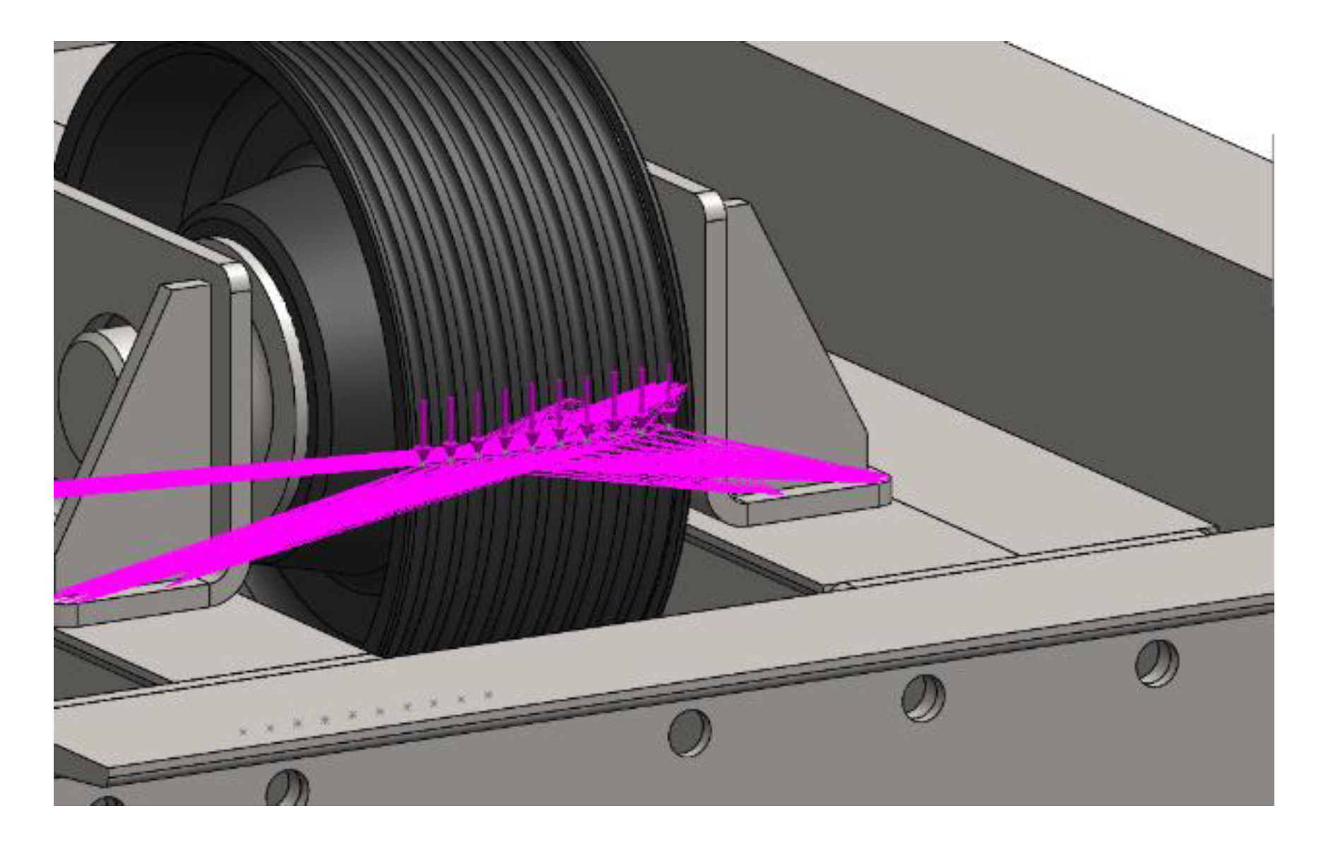
Distribution of forces loading the rope wheel defined as the remote load.
Figure 9.
Distribution of forces loading the rope wheel defined as the remote load.
Figure 10.
A numerical model of the lift carrying frame in the existing form and for the first case of the load: (a) distribution of stresses, (b) distribution of nodular displacements increase.
Figure 10.
A numerical model of the lift carrying frame in the existing form and for the first case of the load: (a) distribution of stresses, (b) distribution of nodular displacements increase.
Figure 11.
The optimized numerical model of the frame with the boundary conditions: a bottom view.
Figure 11.
The optimized numerical model of the frame with the boundary conditions: a bottom view.
Figure 12.
The optimized version of the frame discrete model.
Figure 12.
The optimized version of the frame discrete model.
Figure 13.
The optimized numerical model of the lift carrying frame in the 1st load case (a) distribution of stresses, (b) distribution of nodular displacements increase.
Figure 13.
The optimized numerical model of the lift carrying frame in the 1st load case (a) distribution of stresses, (b) distribution of nodular displacements increase.
Figure 14.
The load resultant force of the carrying frame: (a) in the system prior to optimization, (b) in the system after optimization.
Figure 14.
The load resultant force of the carrying frame: (a) in the system prior to optimization, (b) in the system after optimization.
Figure 15.
The share of the structure weight and installation time in the respective solutions of the power unit carrying frame in the friction lift.
Figure 15.
The share of the structure weight and installation time in the respective solutions of the power unit carrying frame in the friction lift.
Table 1.
The parameters analised structures.
Table 1.
The parameters analised structures.
| Name of Variable | Designation | Value | Unit |
|---|
| Load capacity | Q | 1000 | kg |
| Weight of the cabin with the frame | P | 1130 | kg |
| Transmission ratio | r | 1 | - |
| Number of ropes | n | 10 | pcs |
| Diameter of the carrying rope | d | 10 | mm |
| Counterweight mass | Mcwt | 1630 | kg |
| Weight of the carrying ropes on the cabin side for the 1st case | MSRcar1 | 60 | kg |
| Laden weight of a traveling cable for the 1st case | MTrav1 | 0 | kg |
| Weight of the ropes extender/leveling chains together with the cable wheels weights | MComp | 0 | kg |
| Friction force in the shaft (performance efficiency of bearings on the cabin side and friction on the guides) | FRcar | 99 | N |
| Laden weight of carrying ropes on the counterweight side for the 1st case | MSRcwt1 | 0 | kg |
| Laden weight of leveling ropes on the cabin side for the 1st case | MCRcar1 | 0 | kg |
| Friction force in the shaft (performance efficiency of bearings on the counterweight side and friction on the guides) | FRcwt | 20 | N |
| Laden weight of carrying ropes on the cabin side for the 2nd case | MSRcar2 | 0 | kg |
| Laden weight of carrying ropes on the counterweight for the 2nd case | MSRcwt2 | 60 | kg |
| Laden weight of leveling ropes on the cabin side for the 2nd case | MCRcar2 | 0 | kg |
| Laden weight of leveling ropes on the counterweight side for the 2nd case | MCRcwt2 | 0 | kg |
| Laden weight of carrying ropes on the cabin side for the 3rd case | MSRcar3 | 60 | kg |
| Laden weight of carrying ropes on the counterweight side for the 3rd case | MSRcwt3 | 0 | kg |
| Laden weight of leveling ropes on the cabin side for the 3rd case | MCRcar3 | 0 | kg |
| Laden weight of leveling ropes on the counterweight side for the 3rd case | MCRcwt3 | 0 | kg |
| Delay in the cabin braking process | a | 0.5 | m/s2 |
| Reduced weight of the cable wheel on the cabin side | mPcar | 0 | kg |
| Reduced weight of the cable wheel on the counterweight side | mPcwt | 0 | kg |
| Reduced weight of the extender cable wheel (2 cable wheels) | mPTD | 0 | kg |
| Reduced weight of the deflecting wheel | mDP | 6 | kg |
| Laden weight of carrying ropes on the cabin side for the 4th case | MSRcar4 | 0 | kg |
| Laden weight of carrying ropes on the counterweight side for the 4th case | MSRcwt4 | 60 | kg |
| Laden weight of leveling ropes on the cabin side for the 4th case | MCRcar4 | 0 | kg |
| Laden weight of leveling ropes on the counterweight side for for the 4th case | MCRcwt4 | 0 | kg |
Table 2.
The values of forces which load the frame system of the friction lift.
Table 2.
The values of forces which load the frame system of the friction lift.
| | T1 (N) Force | T2 (N) Force |
|---|
| Case I | 23,842 | 16,010 |
| Case II | 11,246 | 593 |
| Case III | 22,485 | 15,192 |
| Case IV | 10,678 | 17,413 |
Table 3.
The values of numerical calculations of the maximum nodular stresses and displacements values.
Table 3.
The values of numerical calculations of the maximum nodular stresses and displacements values.
| | Stresses (MPa) | Displacements (mm) |
|---|
| Case I | 407.2 | 0.437 |
| Case II | 192.2 | 0.206 |
| Case III | 383.9 | 0.413 |
| Case IV | 182.8 | 0.353 |
Table 4.
The values of numerical calculations of the maximum nodular stresses and displacements.
Table 4.
The values of numerical calculations of the maximum nodular stresses and displacements.
| | Stresses (MPa) | Displacements (mm) |
|---|
| Case I | 307 | 0.977 |
| Case II | 145 | 0.459 |
| Case III | 290 | 0.921 |
| Case IV | 138 | 0.441 |
© 2020 by the authors. Licensee MDPI, Basel, Switzerland. This article is an open access article distributed under the terms and conditions of the Creative Commons Attribution (CC BY) license (http://creativecommons.org/licenses/by/4.0/).


