Abstract
In modular construction—a type of industrialized construction—production planning is very important, as it is closely related to the project’s duration, quality, and sustainability. The constraints (production area, delivery due date) often differ for each project, yet production planning in modular construction has failed to change with the project characteristics. As a result, bottlenecks and construction delays are common problems seen in modular construction, which, in turn, decreases the production ratio, causing the production to be inefficient. To this end, this paper applied a prefabricated component in the modular production process. The paper developed a process analysis model considering constraint factors (production period, production area) to derive the optimal configuration of the prefabricated components in various alternatives. The developed analysis model was then applied to a virtual case to analyze the productivity improvement and select the optimal process. The optimal production process was derived by simulating the possible production planning within a limited production area and production timeline. The result of a simulation indicates that the production period has been halved by optimizing the process. Furthermore, by applying prefabricated components, the production efficiency was further increased because the existing linear production process’s bottleneck disappeared. The model is deemed to have the potential to optimize various production methods across production facilities or modular factories that simultaneously perform multiple projects.
1. Introduction
Modular construction involves the production of construction components (e.g., structures, materials, various types of equipment) that are built off-site, and modules are assembled with minimal effort on-site [1,2,3]. In modular construction—a type of industrialized construction—factory production is very important, as it is closely related to the project’s duration, quality, and sustainability. The advantages of modular construction are a shortened construction period, superior quality, transport and reuse of materials, and reduced construction costs [4,5,6,7]. As such, modular construction is becoming increasingly popular worldwide, providing a solution to the lack of skilled laborers, rise in labor costs, decrease in productivity, and sustainable construction [8,9].
Generally, a production process is determined by the type and quantity of components, delivery and production plan, and resource (e.g., material, labor, and equipment) plan. However, in modular construction, the characteristics of the construction industry must be considered. In other words, it is heavily impacted by the characteristics of the order-based industry and multi-product mass productions (multiple projects happening at the same time) [6]. Order-based industry requires a fixed module delivery period, and limited use of factory sites from running multiple projects at the same time can have a considerable impact on productivity [10]. In particular, variables such as project conditions (production timeline, factory areas) and project requirements should be considered in the factory planning process in multi-product mass production (multiple projects) [6,10,11]. However, multi-product mass production is currently very challenging to be considered in modular construction due to bottlenecks [12,13].
A bottleneck is a congestion in a production system that causes a delay in the entire production process, usually caused by production capacity constraint factors [14,15]. In other words, a product fails to move onto the next phase and remains stagnant, which causes a delay in the entire construction process and idle personnel [16]. Adequate working hours and breaks are required to resolve this problem. However, if the quantity of work exceeds the working time, the waiting time lengthens, which decreases labor productivity. On the opposite side, it causes bottlenecks to occur continuously, which hinders the optimization process. In particular, in Korea’s modular factory production process, bottlenecks usually occur in the wet construction method.
Such a problem can be resolved by prefabricating building components in production planning [6,17,18]. In other words, prefabricated components can reduce bottlenecks, improve production rates, and shorten production times; even though, prior studies lack research and analysis of the levels at which prefabricated components are used.
Modular construction research is mostly related to production planning optimization. The literatures are mostly on improving productivity for module production, which is dedicated to unit module production, including personnel, equipment management, factory layout, and production management characteristics. Production line optimization, factory layout optimization, and lean production are a few examples of production optimization. Kim, Park, Lee, Suh, Lee and Kim [13] developed and tested a new model that clustered activities based on the number of information flows between activities, where clustered activities were allocated to the secondary production line to simplify the main production line. Senghore et al. [19] used discrete event simulation (DES) to analyze the utilization of production personnel. Abu Hammad [20] used simulation to predict production and bottlenecks to develop a model where manufacturers can manage effective modular construction.
Hammad et al. [21] tried to remove bottlenecks using the line balancing approach to optimize the production process. They also derived a decision-making model that can choose the optimal layout using workflow patterns. Meanwhile, Mehrotra et al. [22] developed efficient layouts for the five types of modular factory pattern, given the relationship between activities and space layouts using FactoryPLAN and BLOCPLAN software. Banerjee et al. [23] regarded the inefficient transport of materials and equipment within the factory as the biggest obstacle to modular construction optimization. They proposed an alternative layout by minimizing the number of items transported, transport distance, transport time, transport cost, and equipment utilization.
Mullens [24] proposed an optimized modular construction process that unifies the production time and decreases production bottlenecks for each production process using the value stream map (VSM) model. Moghadam et al. [25] proposed an integrated model that mixed building information modeling (BIM) and lean construction techniques in the modular construction process. VSM was produced by applying lean construction techniques to decrease idle time. As a result of applying VSM in simulation, the production time decreased from 17 days to 5.7 days.
However, almost no previous studies are related to multi-product mass production, which is a modular construction characteristic. Therefore, this study attempts to identify the optimal process based on production time and production space (area) depending on the application of prefabricated components. In other words, the objective of this study is to develop the optimal production process that considers the main constraint factors: delivery time and factory size. To achieve this goal, the paper proceeds with the following steps:
- (1)
- Generalizing unit module production with specifically related components, and analyze the connection among components to analyze the combination conditions among components.
- (2)
- Developing analysis model for optimizing modular factory production considering factory area, and production time. It uses the objective functions depending on the limitation (area, time) to decide the optimal combination for project components.
- (3)
- Model application using virtual scenario to assess the alternatives to the combination of components and derive the optimal production planning process for different project conditions.
2. Method and Model Development
The method and model development of this study involved several processes. First, the production process of the generalized modular unit was reviewed by setting the unit module and monitoring the factory production. Second, each factory production process was analyzed to identify the tasks and the components used; furthermore, the interdependency between components was analyzed using DSM (dependency structure matrix). Third, a generalized modular assembly process and its time were established based on the assembly rules defined in the DSM results and the monitoring results. Fourth, this generalized modular assembly process was used to develop a simulation model that can generate and analyze possible alternatives according to the project characteristics (factory area, time limit).
2.1. Generalization Unit Module Production Process
2.1.1. Component Analysis of Unit Modular Using DSM
To componentize unit modules and derive the optimal process, a close examination of the unit module production process is required. This study monitored factory production to analyze the unit module production process. The most popular type of residential modular construction of a company with extensive experience was selected as the subject of monitoring. Monitoring included route, input personnel and equipment, materials, and working time.
Unit module production processes are formed by one production line, so the work is carried out sequentially. The factory is largely divided into a workspace inside the factory, a yard space, a floorplate production, and a concrete placement space. In particular, the deck is made by concrete pouring, which is arranged outside the factory and requires several transportation operations. Except for the external workshop, the internal module production flow is U-shaped and consists of a linear production line [16,26]. Lee, Park, Lee, Kim, Kim and Hyun [16] have 12 stations for modular factory production, and KICT [26] have 7~12 stations for unit module production.
The main purpose of analyzing the modular units is to identify the module production process. Therefore, this study selected a simple but representative residential modular construction in Korea. Specifically, this study selected a dormitory with four walls (3300 mm × 6600 mm × 3000 mm) as the unit model to generalize the production process. Although the unit module area is not ample, the unit module incorporated most activities required for the residential building, including a floor heating system. Despite satisfying the minimum requirement of area per person for social background, the dormitory offers an additional separated area on the first floor of each building. Furthermore, multiple unit modules can be combined to provide a larger space for one cell [26,27]. The unit module is a corner supported type with a steel column beam and a cast-in-place concrete floor. The gypsum board was used as the basis of the wall and ceiling. Depending on the area, different types of gypsum board (fireproof, general) were used in two layers. Wallpaper was used to finish the gypsum board. The floor was finished with vinyl tiles after the insulation. Lightweight foamed concrete, cement mortar, and hot water pipes were installed. The insulation performance of each part of the modular unit is designed to meet the standards outlined in Article 14 of the Green Buildings Construction Support Act (Submission of Energy Saving Plans) notified by the Minister of Land, Infrastructure, and Transport of the Republic of Korea. Additionally, this study monitored factory production to analyze the unit module production process. The most popular type of residential modular construction of a company with extensive experience was selected as the subject of monitoring. Monitoring included route, input personnel and equipment, materials, and working time.
Unit modules can be broken down into components based on the DSM to understand what components can be prefabricated for assembly because many components can be assembled both internally and externally in a station [28]. The study used the dependency structure matrix (DSM) for analyzing the connectivity among components and preassembly for clustering [29]. DSM is a network modeling tool to express the interaction between elements of a system in a N × N matrix [30,31]. For the application of DSM, interaction type and interaction strength should be defined.
Interaction type means a type of relationship among components that construct a single unit. The connection between components can be categorized based on how the components meet and how they physically merge. First, the methods by which materials meet can be classified using surface, line, and dot. Based on such categories, they can be divided into six types: surface versus surface, surface versus line, surface versus dot, line versus line, line versus dot, and dot versus dot. As an example, if the gypsum board is installed on the lightweight steel that constitutes a wall, the lightweight steel would be a line, and the gypsum board would be the surface, which means the gypsum board (surface) is on top of the lightweight steel (line). Therefore, joining occurs when a surface comes in contact with a line. The type of joints refers to how the components attach. There are six types of joints: welding, bolts, screws, pin, regular joints, and simple joints. A simple joint here means there is no joint between the two (A, B) components, but a third component is joined to each, which causes A and B to be joined. The joint method in the above example (lightweight steel and gypsum board) is a screw joint. The physical junction relationship can be further divided into 36 combinations, depending on the bonding type and method.
where IS is the interaction strength, ITCA is the contact area, and ITCM is the bonding method. In accordance with the DSM analysis order, the strength of the impact and relationship of the interaction type must be derived among singular module components. Interaction strength can be defined as binary or by assigning a weighted value [32]. In this study, two types of factors (contact area, bonding method) were multiplied to calculate the relative interaction strength [30,32] as shown in Equation (1).
Therefore, the contact area would have the biggest impact on the surface versus surface and the smallest impact on the dot versus dot. In other words, starting with the smallest value of 1 (for dot versus dot), each unit increased by 1, with the surface versus surface at the highest value of 6. On the other hand, a simple joint would be 1, a bond or tape bond would be 2, a pin connection would be 3, and a screw connection would be 4 points. However, welding and bolting would have relatively higher values (bolting 9, welding 10) because welding and bolting are much stronger than other bonding methods. Based on such assumptions, a total of 36 types of the interaction strength between components were calculated. A simple junction is the smallest when it is the dot versus dot and biggest for welding on the surface versus surface with 60 points. A matrix was formed using such an assumption, which was then subjected to a quantitative analysis of the relationship between components. As a result, there are 7 clusters defined: Cluster 1 (short-side wall) has 13 components, Cluster 2 (long-side wall) has 9 components, Cluster 3 (outer wall) has 2 components, Cluster 4 (floor) has 9 components, Cluster 5 (ceiling) has 10 components, Cluster 6 (pipe shaft) has 2 components, and Cluster 7 (bathroom) has 10 components.
Figure 1 is a visual representation of the DSM matrix of short-side wall. Depending on the interaction strength, green represents a bigger correlation, and red represents smaller interactions [16,33]. For example, the strongest interaction for the short-side wall (i.e., Cluster 1) are the materials that constitute the structure; studs and tracks, the backbones of the finishing materials for the wall, have the strongest interaction with the structure. Studs and tracks also have strong interactions with the finish, as shown in Figure 1.
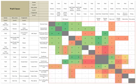
Figure 1.
Wall cluster.
2.1.2. Assembly Rules of Unit Modular Component
Prefabrication means the omission of construction and assembly of some prefabricated components in the existing module production process. In other words, multiple processes can be converted into a single process using prefabricated components. However, reasonably designing production processes that will change due to the prefabrication have a few systematic constraints. First, pre-assembled parts must be set up due to the relationship between processes. For example, during dry wall construction, the gypsum board cannot be installed without tracks and studs [26]. In other words, the preceding process must be completed for the subsequent process to take place. Second, the existing production planning process that requires more than two components simultaneously should be merged. For example, both columns and beams are required during the short-side structure manufacturing process, which means that in the short sidewall prefabrication process, both columns and beams must be used as prefabricated products. Third, the Ondol floor heating system in the bathroom, which is unique to Korean construction, must be considered. A bathroom may be produced as a prefabricated unit bathroom (UBR) or as a single unit, and the ondol floor system does not use the current wet method but rather, a dry method that uses existing products. The following Table 1 outlines the constraints for each cluster based on the three assumptions.

Table 1.
Constraints (rules) for assembly of prefabricated components for each cluster.
2.1.3. Rule-Based Modular Assembly Production Process
The linear production method can benefit the most from the factory layout and prefabricated components. Often referred to as continuous production, linear production refers to a process where each production step proceeds in order. The workers work as all the modules, workers, equipment, and materials are located in a designated place with a rail or conveyor belt installed [4]. In other words, the number of production lines and cycle time determine the process of continuous production, which means prefabricated components may have a bigger impact on this method than any other production method. The modular planning process in linear production can be categorized using the concept of the station. The station refers to the point in linear production where the work takes place. It is typically divided into the Pre-Station, Station, and Post-Station. The Pre-Station refers to steps until unit modules form a box frame, the Station refers to the process where unit modules move along the rail for finishing, and the Post-Station refers to remaining work and packaging as well as transport (shown in Table 2). Here, the manufacturing time for each process was derived by monitoring the production process in modular factories. In addition, in the study, each task was allocated in an identical task area with the consideration of the detailed process, cluster, and work continuity (as shown in Figure 2).
Table 2.
Modular manufacturing process in linear production.
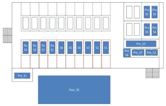
Figure 2.
Factory layout for linear production.
Once the activities in Table 2 are integrated as prefabricated components, depending on the component combination, the corresponding activities disappear, and the deleted activity is replaced with the prefabricated components’ installation activity. Once the activity is replaced, the process may face a partial change, and therefore, the task time will change. Here, the time required to perform the altered process is not the sum of the times of activities to manufacture the corresponding components; rather, it is replaced by the time of the earliest work that constitutes the prefabricated component. Additionally, if there is any change in the process due to prefabrication, 10 min are added to reflect the quality inspection process [32]. In addition, the installation difficulty level will increase during prefabricated component manufacturing. According to the analysis result of manufacturing time and installation time for the prefabricated lightweight steel and gypsum board, the production time lengthened. Table 3 presents the results of the analysis of the production time and installation time for the prefabrication of lightweight steel and prefabrication of both lightweight steel and gypsum board. The result shows that the total time increased when both the lightweight steel and gypsum board were prefabricated. In other words, even when using prefabrication, converging lightweight steel and gypsum board will cause both walls to be blocked, which means directly screwing the lightweight steel to the structure frame is no longer possible. Instead, connecting hardware must be additionally installed. The study reflected the additional time for the installation of the connecting hardware (L-shaped angle). In other words, when both lightweight steel and gypsum board are prefabricated, an additional 20 min are added [34], which includes the short and long sidewalls.
Table 3.
Production and installation time for prefabricated lightweight steel and lightweight steel and gypsum board [34].
2.2. Model Development
2.2.1. Model Assumption
The model assumes one production line with 480 working minutes (8 h) per day. The required area for the process is 5.3 m (horizontal) by 15.6 m (vertical) after considering the size of the unit module, working space, and materials’ storage space. The time it takes for the module to move from the Pre-Station to the Station or to move to the outside is 15 min. The time between stations is assumed to be 5 min. In general, the factory area can be used for more than one purpose, such as loading components, allocating equipment, moving personnel, moving equipment, and loading unit modules. In other words, the total area of the factory is not always fully dedicated to the production process. Therefore, only a small percentage of the total factory area should be allocated for module production. The analysis of the existing factory utilization showed the total factory area used for purposes other than production, including equipment transportation. Based on such analysis, the total allocatable area for production was assumed to be 55% of the total factory area. Table 4 summarized assumptions used in the simulation model.
Table 4.
Assumptions for simulation.
2.2.2. Objective Function for Optimal Process Selection
The main constraints given in advance for the delivery and manufacturing of modules are the total factory area and the target deadline (delivery date). The producer can determine the daily module production target and derive a production plan to meet the schedule [35,36,37]. Here, various production methods (prefabrication ratio) may exist, and the number of scenarios may vary. That is why an objective function is needed to choose the optimized production method. For example, if we assume the simulated process for the given constraint factors as purple from the below diagram (Figure 3), three (3) objective functions exist.
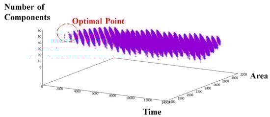
Figure 3.
Selection of optimal process.
As an area function, the difference between the total utilized factory area should be minimized as shown in Equation (2). In other words, we can assume that the area is used as much as possible under the given constraint factors. Furthermore, the production time of the module should be minimized as shown in Equation (3).
where FA indicates the available area in the factor, Ai indicates the area required for the i-th process, and OCi is a binary variable that shows whether the i-th process occupies space in the factory.
where MPTi indicates the module production time for the i-th modular production.
Finally, the total number of components included in the prefabricated components was used as another criterion. The total number of components is related to the quality and complexity of work. If the number of components included in the prefabricated component is high, the number of tasks in the factory decreases, decreasing the complexity within the same task area. If the activities performed in a working area exceed a certain number, the working area might become congested and, therefore, less efficient [13,16,38]. In other words, even if it takes more time in the same area, if the number of prefabricated components increases, the number of tasks in the factory will decrease, causing the efficiency of construction to increase. Therefore, we assume that the optimal process is when the number of components in the prefabricated components is the highest as shown in Equation (4).
where PCi indicates the prefabricated components in the modular production.
2.2.3. Model Development
The module production process, linear production method layout, and objective function were all used to develop the model. First, process time, time code, area, and area code were all assigned to each component. For example, the working time, area, and area code for the columns and beams used on the outer short sidewall frame can be defined as shown below in Table 5. Similar attributes were assigned to all components.
Table 5.
Examples of components.
Combinations created by such component codes were matched one-to-one to derive prefabricated components. However, derived prefabricated components can vary depending on the number of projects and the number of vendors that produce the prefabricated components. If there was more than one component manufacturer, the total number of cases derived from the combination of prefabricated components was applied. If there was only one vendor, then the prefabricated component that contained the largest number of components was uniformly applied. That is because if there is only a single vendor, a different prefabricated component may fail to produce the combination required by the project. For example, the prefabricated component for the short sidewall in Project A may require both lightweight steel and gypsum board, but all prefabricated components were included for short sidewall for Project B. Here, it is impossible to apply the prefabricated component on the same production line, as it is different for each project. To this end, the prefabricated component that required the highest number of components was uniformly applied. By doing so, all possible processes were derived by applying the prefabricated process based on the number of manufacturers. Constraint factors (required module quantities, factory area, delivery period) were applied to derive the optimal process (Figure 4).
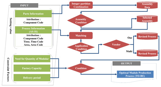
Figure 4.
Model architecture.
2.2.4. Defining Component Information
The component code must be defined to enter the information related to components. The code is in three digits, where the first and the second digits indicate the assembly location. The short side wall is SW, the long-side wall is LW, the exterior wall is EW, the floor is BT, the ceiling is CL, the pipe shaft is PS, and the bathroom is TW. The last digit is from 1 to n to indicate the number of components. In addition, to analyze the components and the production line together, we need to map each process. To this end, component code, working time, and required area were all assigned unique codes (shown in Table 6).
Table 6.
Attributes for each process.
The data in Table 6 is used to create a simulation model using Python, a programming language. The model integrates the information in Table 1, Table 2, Table 3, Table 4 and Table 5. For example, column assembly and beam assembly cannot be separated because the parts that make up the structure must always be together (Table 2 and Figure 5). In addition, when a prefabricated assembly replaces the existing process, the manufacturing time is changed. As shown in Figure 6, by applying the short-side wall assembly, the short-side wall assembly time is replaced by zero, and a new area code was assigned.
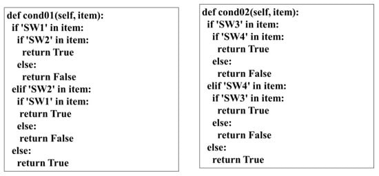
Figure 5.
Example of the code of the constraints of component combination.
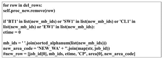
Figure 6.
Example of the code of time calculation.
2.2.5. Prefabricated Component Combination Results
The number of combinations for module components is 11 for the short-side prefabricated components, 6 for the long-side prefabricated components, 3 for the exterior wall panel, 10 for the floor panel, 7 for the ceiling, 2 for the pipe shaft, and 3 for the bathroom. If all seven parts were applied to the entire model, there would be 83,160 possibilities for prefabrication. However, it is reasonable to maintain the process that causes a bottleneck to analyze the effect of prefabricated components. In addition, because the prefabricated components of exterior wall panels and pipe shafts are not Critical Path (CP), the prefabricated components have no effect; therefore, they were excluded. Therefore, the prefabricated components to be applied in the lean production method were applied to the short sidewall and long sidewall.
For the short-side wall, the components for the Station are SW3 and SW13. Categorizing the prefabricated and non-prefabricated components based on the constraint factors yielded 10 cases. The prefabricated components for the short-side wall are components that can be assembled based on steel frames. Using the same method on the long side yields a total of six cases. Other components are assembled and sent as prefabricated components based on the long sidewall track (LW1) and stud (LW2).
Based on the process defined from the 60 different cases in Table 7, different times and working areas were allocated. Assuming a total of 100 modules were produced, the result is shown in Table 8. The component combination in Table 8 shows the combination of the short sidewall and the long sidewall of Table 7. The number of stations indicates the number of stations after the prefabricated components were applied. The internal factory area is the sum of the needed working area and the material area for the production process, and the production time is the time needed to produce 100 module units (Table 8). In Table 8, the first case when the number of stations decreased is Category 5, with the combination of prefabricated components of LW1, LW2, LW3, LW4, LW6, LW7, LW8, and LW9. However, the number of stations did not decrease for Category 6, which consists of LW1, LW2, LW3, LW4, LW5, LW6, LW7, LW8, and LW9. That is because when the prefabricated component that includes all components is produced, additional time is required to connect the prefabricated component to the module unit steel frame. This study added 20 min for the difficulty in the task to reflect as many real variables as possible.
Table 7.
Number of cases of prefabricated parts on short and long sides.
Table 8.
Simulation results for each case of prefabricated components for short and long sides.
The table above only shows the results of simulating the prefabricated components of the long sidewall and the short sidewall, but various other simulations are also possible. For example, if concrete in the floorplate production process is produced in the module factory, the production time can be shortened by changing all the work related to the floorplate production to prefabrication. That is, a number of simulations are possible by applying various types of prefabricated components according to the construction period given to the project. By doing so, we can adjust the overall module production planning.
3. Results and Discussion
3.1. Model Application
3.1.1. Virtual Project Information
A hypothetical scenario based on a real modular construction factory was designed to investigate the applicability of the results of this study and analyze the effect indirectly; that is because only a few cases in the linear production method were used, but applying the case is judged to be the most suitable for verifying the usefulness of this model given that the assumptions closely reflect reality [39]. The hypothetical project used for the case study was based on the factory layout and module working time of a company with the highest module production performance in Korea. In this scenario, the module production time in a total area of 4550 m2 was analyzed using the linear production method (Table 9).
Table 9.
Overview of virtual project.
3.1.2. Analysis of Existing Factory Manufacturing Process
The existing processes of the modular factory include 11 Pre-Station processes, nine Station processes, and 13 Post-Station processes. There are nine Pre-Station working areas, nine Station working areas, and one Post-Station working area. The analysis showed that the application of wet construction methods and four curing processes resulted in bottlenecks and idle times. As shown in Figure 7, a certain number of floor frames must be completed to place the deck concrete (Pre-S2), and additional time is required for curing. Cured bottom plates are sent for the following assembly. However, a bottleneck occurs because the multiple floorplates cannot be assembled for the module unit at the same time. A delay occurs as a result of the consequential delay in module unit assembly. For the same reason, the installation of the heating pipe is delayed due to the pouring and curing of lightweight concrete. Due to curing of the floor plastering after the installation of the heating pipe, there is a delay in finishing and packaging. Therefore, the first module production period was set as 15 days (Table 10).
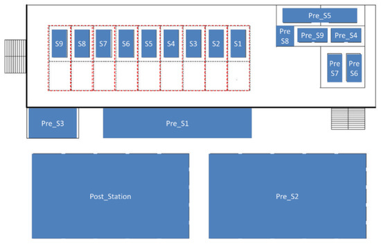
Figure 7.
Existing factory layout.
Table 10.
Analysis of existing factory manufacturing process.
3.2. Model Application Result and Discussion
To analyze the application effect of prefabricated components, the prefabrication process of the short sidewall and the long sidewall analyzed in Table 7 was applied (but maintaining the existing process). The number of stations was reduced to four, and it was expected that the total module production time would be shortened accordingly (Table 11).
Table 11.
Module productivity analysis after prefabricated component application.
The result of a simulation is shown in Figure 8. The x-axis indicates duration, and the y-axis represents the number of modules. Therefore, Figure 8 shows that the revised process reduces the duration required to produce 200 modules from 81 days to 41 days. The slope of each graph indicates the production rate speed, similar to the Line of Balance Method in the construction schedule management. Therefore, a steeper slope for the revised process implies a faster production speed than the baseline process. In other words, applying prefabricated components enabled continuous production at the station, and production efficiency was further increased as the bottleneck of the existing linear production process disappeared.
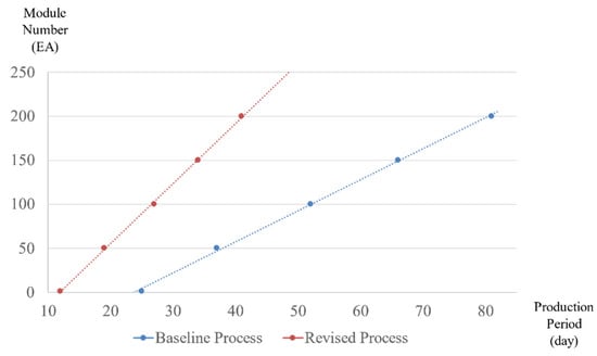
Figure 8.
Comparative analysis of module production period between processes.
As a result of the model application, a new process using assembly parts was mainly derived from wall construction (Table 10 and Table 11). The reason is that the application of assembly parts in wall construction can be optimized in various ways. However, in some cases, it can also be applied to concrete deck construction. In the baseline process, a bottleneck can occur because it is necessary to wait for a certain number of deck frames to gather the amount of concrete, and the assembly of the module units for subsequent work is delayed due to waiting and curing time [13,14]. However, if a prefabricated deck is applied, assembly of the module unit can begin immediately on the first day. Accordingly, it is possible to complete other finishing work in a linear production without delay due to removing the curing task from the existing process. Therefore, production without any changes to the factory production ratio within the given production period is possible. It is also possible to shorten the production period using prefabricated components, such as floorplates and toilets.
4. Summary and Conclusions
The modular construction method is a more sustainable construction method compared to the existing construction method like Cast-in situ construction, and in that perspective, modular can be recycled and reduce site waste. However, the problem with the existing modular construction production process is that it is a mix of processes with a long period and a short period. These can often create the causes of challenges in labor management and bottlenecks. Therefore, the study attempted to apply prefabricated components to shorten production time and reduce the production area by removing any tasks that cause the bottleneck phenomenon. To this end, the study generalized the module production process through the analysis of the general modular manufacturing process and the relationships between each part of the process. In addition, the objective function according to the factory area, delivery period, and the number of parts was defined and implemented to derive the optimal combination of prefabricated components. Then, a case study was performed to analyze the applicability and effectiveness of the findings from this study. The model eliminated any elements that caused a bottleneck, and as a result, a smoother production line and shortened production time were possible. This model can be a tool for measuring and judging the pre-assembled degree when project conditions are different for each project, and determining the level of prefabricated components.
Sustainable construction has been gaining increasing interest from academia and industry due to the increasing importance of sustainability in our society. Industrialized construction has been proposed and adopted in the construction industry as a new production system to improve sustainability. Industrialized construction can reduce construction waste and improve the reuse and recycling of materials by manufacturing building components in a factory and assembling the components on the construction site. Among the diverse levels of industrialized construction, modular construction involves the highest prefabrication level (i.e., prefabrication of volumetric modules in a factory). In this sense, the optimization of the module production process suggested in this paper may contribute to improving the sustainability of the construction industry. Optimized configuration of the prefabricated components may reduce the waste and delay, which may hamper the sustainability of the production process. In response to this comment, the following statements have been added in the summary and conclusion to emphasize this paper’s contribution with respect to sustainability.
However, it should be noted that the assumptions presented in this paper could be a limitation. Data for input variables presented in this paper, such as the production time, are collected from residential modular projects in South Korea. Therefore, it may not be easy to apply the same values in other situations. Although the model in this study used input values from the analysis of modular housing projects, it does not necessarily mean that the values of the input variables are fixed in the model. The values of input variables can vary based on project conditions. For example, the duration of each work task for other projects could differ from the values in the case project model based on the productivity data. In this sense, the current study developed a framework that integrates the DSM and process optimization model to identify the optimal prefabricated components in a given situation. Furthermore, this study focused on wall prefabrication, which may not differ across the globe. Therefore, the model developed in this study may have generalizability to other conditions by applying different values to input variables.
Nevertheless, this study confirmed that the prefabrication of components in a single module could result in a smoother production line and shorter production time by removing any elements that cause bottlenecks. In addition, it will be possible to minimize any on-site construction since it is possible to manage the factory production ratio. The results of this study contribute to selecting factory production processes suitable for module construction factories of various sizes or factories that perform multiple projects, as it decreases the timeline and required area. As such, the results can be used as a preliminary analysis for the application of flying factories.
Author Contributions
Conceptualization, S.N.; methodology, S.N., B.C. and K.K.; validation, S.N. and J.Y.; formal analysis, S.N.; writing—original draft preparation, S.N. and J.Y.; writing—review and editing, J.Y. and B.C.; supervision, B.C. and K.K. All authors have read and agreed to the published version of the manuscript.
Funding
This research was supported by grant number 20RERP-B082884-07 from the Housing Environment Research Program funded by the Ministry of Land, Infrastructure and Transport of the Korean government.
Conflicts of Interest
The authors declare no conflict of interest.
References
- Lee, C.-J.; Lim, S.-H. An Analysis on Architectural Characteristics of Domestic Modular Housing and Building Material Standardization Effect through MC Design. J. Korean Hous. Assoc. 2015, 26, 103–113. [Google Scholar] [CrossRef][Green Version]
- Nam, S.; Lee, D.; Cho, B.-H.; Kim, K. Integrated Management Software for Factory Production of Modular Buildings. Adv. Civ. Eng. 2019, 2019, 1–10. [Google Scholar] [CrossRef]
- Mohsen, O.M.; Knytl, P.J.; Abdulaal, B.; Olearczyk, J.; Al-Hussein, M. In Simulation of modular building construction. In Proceedings of the 2008 Winter Simulation Conference, Miami, FL, USA, 7–10 December 2008; pp. 2471–2478. [Google Scholar]
- Quale, J. Design in Modular Construction. J. Arch. Educ. 2017, 71, 119–120. [Google Scholar] [CrossRef]
- Yoon, J.; Shin, D.; Cha, H.; Kim, K. A Business Model for Application of the Modular Building in the Rental Market. Korean J. Constr. Eng. Manag. 2015, 16, 3–11. [Google Scholar] [CrossRef][Green Version]
- Lee, J.; Hyun, H. Multiple Modular Building Construction Project Scheduling Using Genetic Algorithms. J. Constr. Eng. Manag. 2019, 145, 04018116. [Google Scholar] [CrossRef]
- Alvanchi, A.; Lee, S.; Abourizk, S. Dynamics of Working Hours in Construction. J. Constr. Eng. Manag. 2012, 138, 66–77. [Google Scholar] [CrossRef]
- Bae, B.-Y.; Kim, K.; Cha, H.-S.; Shin, D.-W. To Improve Production Process of the Modular Using the Conveyor System. Korean J. Constr. Eng. Manag. 2012, 13, 103–112. [Google Scholar] [CrossRef][Green Version]
- Martinez, P.; Livojevic, M.; Jajal, P.; Aldrich, D.R.; Al-Hussein, M.; Ahmad, R. Simulation-Driven Design of Wood Framing Support Systems for Off-Site Construction Machinery. J. Constr. Eng. Manag. 2020, 146, 04020075. [Google Scholar] [CrossRef]
- Taghaddos, H.; AbouRizk, S.; Mohamed, Y.; Hermann, R. In Integrated simulation-based scheduling for module assembly yard. In Proceedings of the Construction Research Congress 2009: Building a Sustainable Future, Seattle, WA, USA, 5–7 April 2009; pp. 1270–1279. [Google Scholar]
- Moghadam, M.; Al-Hussein, M.; Al-Jibouri, S.; Telyas, A. Post simulation visualization model for effective scheduling of modular building construction1This paper is one of a selection of papers in this Special Issue on Construction Engineering and Management. Can. J. Civ. Eng. 2012, 39, 1053–1061. [Google Scholar] [CrossRef]
- Abu Hammad, A.; Senghore, O.; Hastak, M.; Syal, M. Simulation Model for Manufactured Housing Processes. Inf. Technol. Civ. Eng. Int. 2002, 286–297. [Google Scholar] [CrossRef]
- Kim, T.-Y.; Park, M.-S.; Lee, H.-S.; Suh, S.-W.; Lee, J.-H.; Kim, S.-Y. Optimization methodology of modular unit factory production process using DSM. J. Archit. Inst. Korea Struct. Constr. 2013, 29, 113–122. [Google Scholar]
- Lee, D.-Y.; Nam, S.-H.; Lee, J.-S.; Jung, D.-I.; Kim, K.-R.; Cho, B.-H. Factory Production Management of Modular Units Using MFD 2019. J. Archit. Inst. Korea Struct. Constr. 2019, 35, 139–146. [Google Scholar]
- Narasimhan, K. The Goal: A Process of Ongoing Improvement. Meas. Bus. Excel. 2005, 9, 76. [Google Scholar] [CrossRef]
- Lee, J.; Park, M.; Lee, H.-S.; Kim, T.; Kim, S.; Hyun, H. Workflow dependency approach for modular building construction manufacturing process using Dependency Structure Matrix (DSM). KSCE J. Civ. Eng. 2016, 21, 1525–1535. [Google Scholar] [CrossRef]
- Browning, T.R.; Yassine, A.A. Resource-constrained multi-project scheduling: Priority rule performance revisited. Int. J. Prod. Econ. 2010, 126, 212–228. [Google Scholar] [CrossRef]
- Anavi-Isakow, S.; Golany, B. Managing multi-project environments through constant work-in-process. Int. J. Proj. Manag. 2003, 21, 9–18. [Google Scholar] [CrossRef]
- Senghore, O.; Hastak, M.; Abdelhamid, T.S.; Abuhammad, A.; Syal, M.G. Production Process for Manufactured Housing. J. Constr. Eng. Manag. 2004, 130, 708–718. [Google Scholar] [CrossRef]
- Abu Hammad, A. Simulation modeling for manufactured housing processes. Master Thesis, University of Cincinnati, Cincinnati, OH, USA, 2001. [Google Scholar]
- Abu Hammad, A.; Hastak, M.; Syal, M. Comparative Study of Manufactured Housing Production Systems. J. Arch. Eng. 2004, 10, 136–142. [Google Scholar] [CrossRef]
- Mehrotra, N.; Syal, M.; Hastak, M. Manufactured Housing Production Layout Design. J. Arch. Eng. 2005, 11, 25–34. [Google Scholar] [CrossRef]
- Banerjee, D.; Syal, M.; Hastak, M. Material Flow-Based Facility Layout Analysis of a Manufactured Housing Production Plant. J. Arch. Eng. 2006, 12, 196–206. [Google Scholar] [CrossRef]
- Review of Factory Design for Modular Homebuilding: Equipping the Modular Factory for Success by Michael A. Mullens. J. Arch. Eng. 2012, 18, 198. [Google Scholar] [CrossRef]
- Moghadam, M.; Alwisy, A.; Al-Hussein, M. In Integrated BIM/Lean base production line schedule model for modular construction manufacturing. In Proceedings of the Construction Research Congress 2012: Construction Challenges in a Flat World, West Lafayette, Indiana, 21–23 May 2012; pp. 1271–1280. [Google Scholar]
- KICT. Representative examples of domestic modular construction. In Smart, Speedy, and Sustainable Modular Building; Korea Institute of Civil Engineering and Building Technology: Goyang, Korea, 2020. [Google Scholar]
- Yang, S.-C.; Lee, J.-S. Evaluation on the Fire Resistance Performance for High-Rise Modular Walls. J. Korea Inst. Struct. Maint. Insp. 2019, 23, 15–22. [Google Scholar]
- Frenken, K.; Mendritzki, S. Optimal modularity: A demonstration of the evolutionary advantage of modular architectures. J. Evol. Econ. 2011, 22, 935–956. [Google Scholar] [CrossRef][Green Version]
- Browning, T. Applying the design structure matrix to system decomposition and integration problems: A review and new directions. IEEE Trans. Eng. Manag. 2001, 48, 292–306. [Google Scholar] [CrossRef]
- Eppinger, S.D.; Browning, T.R. Design Structure Matrix Methods and Applications; MIT Press: Cambridge, MA, USA, 2012. [Google Scholar]
- Yassine, A. An introduction to modeling and analyzing complex product development processes using the design structure matrix (DSM) method. Urbana 2004, 51, 1–17. [Google Scholar]
- Yang, Q.; Yao, T.; Lu, T.; Zhang, B. An Overlapping-Based Design Structure Matrix for Measuring Interaction Strength and Clustering Analysis in Product Development Project. IEEE Trans. Eng. Manag. 2014, 61, 159–170. [Google Scholar] [CrossRef]
- Hölttä-Otto, K.; De Weck, O. Degree of Modularity in Engineering Systems and Products with Technical and Business Constraints. Concurr. Eng. 2007, 15, 113–126. [Google Scholar] [CrossRef]
- KICT. Technical Development of Modular Construction in Mid-High Rise Building and Higher Productivity. Unpublished work. 2015. [Google Scholar]
- Vrijhoef, R.; Koskela, L. The four roles of supply chain management in construction. Eur. J. Purch. Supply Manag. 2000, 6, 169–178. [Google Scholar] [CrossRef]
- Lee, J.; Park, M.; Lee, H.-S.; Hyun, H. Classification of Modular Building Construction Projects Based on Schedule-Driven Approach. J. Constr. Eng. Manag. 2019, 145, 04019031. [Google Scholar] [CrossRef]
- Wu, S.-Y.D.; Wysk, R.A. An application of discrete-event simulation to on-line control and scheduling in flexible manufacturing. Int. J. Prod. Res. 1989, 27, 1603–1623. [Google Scholar] [CrossRef]
- Riley, D.; Sanvido, V. In Space planning for mechanical, electrical, plumbing and fire protection trades in multi-story building construction. In Proceedings of the 5th ASCE Construction Congress, San Diego, CA, USA, 5–7 April 1997. [Google Scholar]
- Rausch, C.; Nahangi, M.; Perreault, M.; Haas, C.; West, J. Optimum Assembly Planning for Modular Construction Components. J. Comput. Civ. Eng. 2017, 31, 04016039. [Google Scholar] [CrossRef]
Publisher’s Note: MDPI stays neutral with regard to jurisdictional claims in published maps and institutional affiliations. |
© 2020 by the authors. Licensee MDPI, Basel, Switzerland. This article is an open access article distributed under the terms and conditions of the Creative Commons Attribution (CC BY) license (http://creativecommons.org/licenses/by/4.0/).