1. Introduction
When a concrete building is subjected to a fire disaster, the ultimate strength and stiffness of the reinforced concrete (RC) columns may be seriously degraded after exposure to fire. In many cases, the concrete elements cannot be fully replaced. To increase the strength of post-fire RC columns, the technique of wrapping thin-walled steel tubes is explored in this paper. At first, two steel half-tubes are placed outside the concrete column after removal of the damaged surface and the installation of the post-drilled rebars if required, then the half-tubes are welded together. Finally, free flow non-shrink grout is infilled in the gap to form a new combined structure. A similar method is widely used in the enhancement of damaged structures by steel tubes. Due to the restraint of the steel tube, the core concrete is placed under triaxial compressions, and the compressive strength is improved, resulting in an enhancement in the ultimate strength and deformation capacity of the member. The thin-walled steel tube for strengthening can be used as a formwork for new concrete to be infilled. Compare with other enhancement methods, it has the advantages of minimum space occupation, easy installation, less pollution, and good durability under high temperatures.
There are several theoretical and experimental studies that have introduced the structure performance wrapping tube enhanced RC column. Isleem and Wang et al. [
1] built a numerical model to estimate the strength of un-reinforced and reinforced rectangular concrete columns confined with fibre-reinforced polymer wraps. The effects of aspect ratio and the size of the cross-section, effective rupture strain of the polymer, corner radius and internal hoop steel reinforcement were discussed. Janwaen and Barros [
2] introduced an efficient confinement method on rectangular reinforced concrete (RC) columns under axial compression using the strips of carbon fiber reinforced polymer (CFRP) wet layup sheets together with a certain level of prestress. The influence of the cross-section aspect ratio of columns on the axial stress–strain response, the strain field in the CFRP and strength increase provided by the different adopted strengthening configurations was investigated. It may be difficult using FRP wet layup sheets to enhance post-fire column structural strength, because any surface of a column above 500 °C should be removed before enhancement and core concrete after a fire with the high temperatures of 250 °C to 500 °C can only be used with weaken strength.
In 1991, K. Yoshimura, K. Kikcuri, and M. Kuroki [
3] published the test results of reinforced concrete columns of square sections enhanced with steel tubes of square hollow sections. Two L-shape steel elements were welded on the roughed surface of the damaged reinforced concrete column, then the gap was infilled by epoxy resin cement aggregate. The experiment data indicated that the ultimate bending strength of the short column was enhanced, and could be fully developed without brittle failure from the shear actions. This strengthening method has been verified to also be valid for the short columns damaged due to brittle shear failure. M. J. Nigel Priestley, Frieder Seible, Yan Xiao, and Ravindra Verma [
4,
5] used elliptical steel tubes to enhance circle and square concrete columns, and carried out experimental and theoretical analysis on the shear strength. The study demonstrated that the enhancement by the wrapping steel tube can significantly improve the shear strength and bending stiffness of the strengthened column. The work was related to the shear failure mode of an RC bridge designed and built before 1971. The models were applied to predict the shear strength of the structure enhanced by circular or elliptical jackets. The axial load level, strength of longitudinal reinforcement, and aspect ratio as well as section shape were investigated and analyzed in an experimental test program. As-built and retrofitted columns were compared. It was shown that all columns enhanced by circular or elliptical jackets have a large improvement on the shear strength.
In 2000, Hui Wu [
6] proposed a method to use a combination of welded steel tubes and stiffeners to enhance square columns. The stiffeners were placed in the area where plastic hinges may occur at the end of the column. The test results verified that the stiffened steel jacketing can prevent brittle shear failure and significantly improve the deformation capacity. The efficiency of the partially stiffened rectilinear steel jacketing was verified, and the ductility of the strengthened elements were significantly improved.
Studies on thin-wall steel tube strengthened post-fire concrete structures, based on the numerical simulation of the temperature field model and mechanical properties, have been carried out [
7,
8]. Considering the effects from the steel tube, concrete reinforcement ratio and strength of the new added concrete, the strength and ductility of RC columns were investigated and discussed. The results indicated that the RC columns were well strengthened by the thin-walled steel tube, and the strength and stiffness of the strengthened specimens were obviously improved, with increased ductility.
In this work, the axial strength and ultimate deformation capacity of the post-fire RC columns after enhancement are tested and presented. The effect of steel tube thickness, the enhancement method and the cross-section are studied and investigated. The practical equations for the axial strength of post-fire RC columns strengthened by thin-wall steel tubes are proposed. Besides the practical calculation equations, the efficiency of axial compression equations and standards of concrete filled steel tube are compared and verified in detail.
2. Experimental Program
2.1. Specimen Details
A total of twelve RC specimens, designed following “Chinese Concrete Structure Design Code” [
9], were fabricated and tested, including eight RC columns of square sections and four RC ones of circular sections.
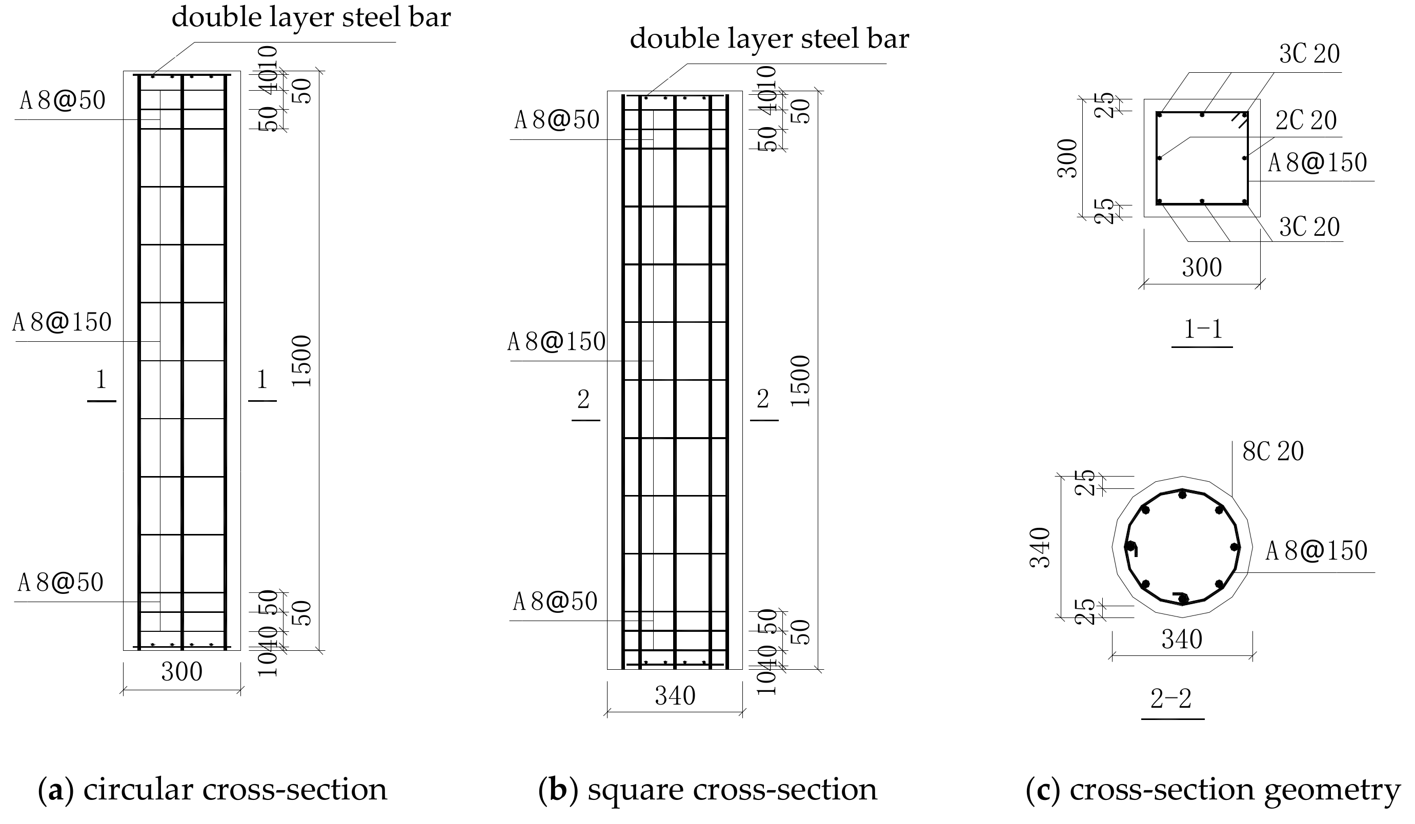
In order to obtain the effect of the section geometry on the efficiency axial compression performance of post-fire RC columns enhanced by thin-walled steel tubes, the similar cross-section geometries of the specimens were adopted. The side length of the square column was 300 mm (the area was 90,000 mm2), and the diameter of the circular was 340 mm (an area of 90,792 mm2), and all the specimens were 1500 mm long.
The parameters of each specimen are given in
Table 1. There are two unfired specimens, SC1 and C1, and two fired specimens without strengthening, SC2 and C2, as bench marks. The specimens SC3, SC4, SC5, SC6, S-C1, S-C2, C3, C4 were fabricated to investigate the effects on the failure mode, stiffness, axial compressive strength and ultimate deformation capacity. The variables of the effects include the thickness of the steel tube (2 mm, 3 mm), the strengthening methods (the steel tube only acting as a restraint, or both restraint and load bearing material), and the section geometry (including square, circular, or section change after strengthening).
The geometry dimensions and reinforcement of each test specimen are shown in
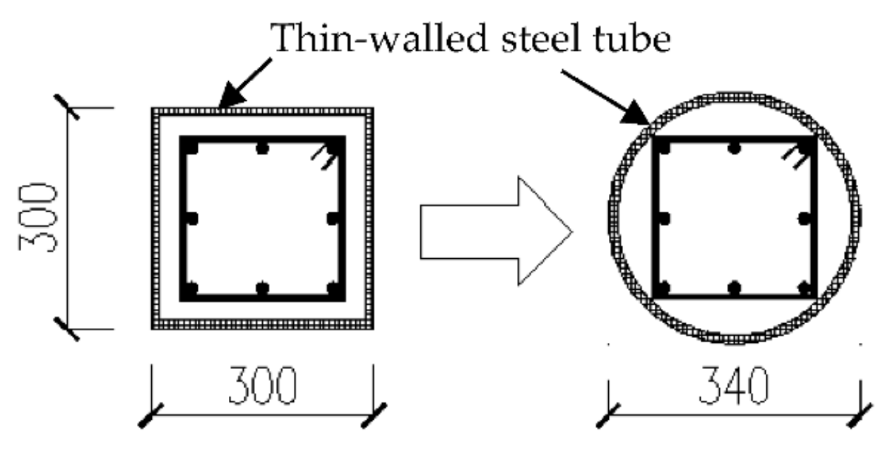
Figure 1. After removing the damaged surface, the test specimens can be enhanced using the thin-walled steel tubes. Keeping the similar cross section geometry as undamaged concrete columns, the grout is infilled in the gap between the tube and column. Steel tube manufacturing is illustrated in
Figure 2a,b. The cross-section geometry was changed from the original 300 × 300 mm square, and strengthened into a circular cross-section with 340 mm diameter after fire; the modified geometry is shown in
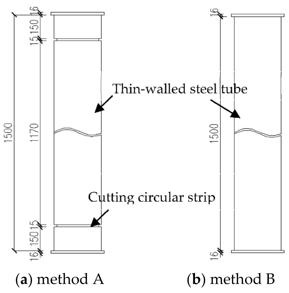
Figure 2c. The strengthening method A was applied to test specimens SC3, SC4, S-C1, C3, where the thin-walled steel tube only acts as a restraint by cutting a circular strip of 15 mm wide at each end of the steel tube at a distance of 150 mm from the end, as shown in
Figure 3a. Strengthening method B was applied in test specimens SC5, SC6, S-C2, C4, where the thin-walled steel tubes bear longitudinal loads in addition to acting as restraints wrapping the whole column.
2.2. Material Properties
The test specimens were poured in two batches sequentially. The first batch included C2, C3 and all square columns, and the second batch included C1 and C4. Three groups of standard test blocks of two batches were made, each side length was 150 mm, in order to check the cube compression strength at 28 days, the day of the fire test and of the axial compression performance test. The post-fire specimens were strengthened by C50 free flow non-shrink grout. A standard cubic mortar block of the side length 70.7 mm was made for testing compressive strength at 28 days (just before the axial compression test). All test blocks and test specimens were cured under the same conditions, and the compression test was carried out in a microcomputer-controlled electro-hydraulic servo universal testing machine according to the Standard Test Method for Mechanical Properties on Ordinary Concrete (GB/T50081-2016) [
10]. The test results are shown in
Table 2.
According to the “Metallic materials—Tensile testing at ambient temperature” (GB/T 228-2002) [
11], the material properties of the steel were tested. All the longitudinal reinforcements were made of HRB400 steel by 20 mm diameter. The stirrups were made of HPB300 steel by 8 mm diameter. The steel plate for enhancement was made of Q235B steel. The tensile test specimen of steel plate was fabricated and formed in the factory. The test results on the mechanical properties of the steel reinforcement and steel plates are shown in
Table 3. The elastic modulus of steel is 203GPa, and Poisson’s ratio is 0.3.
2.3. Fire Test
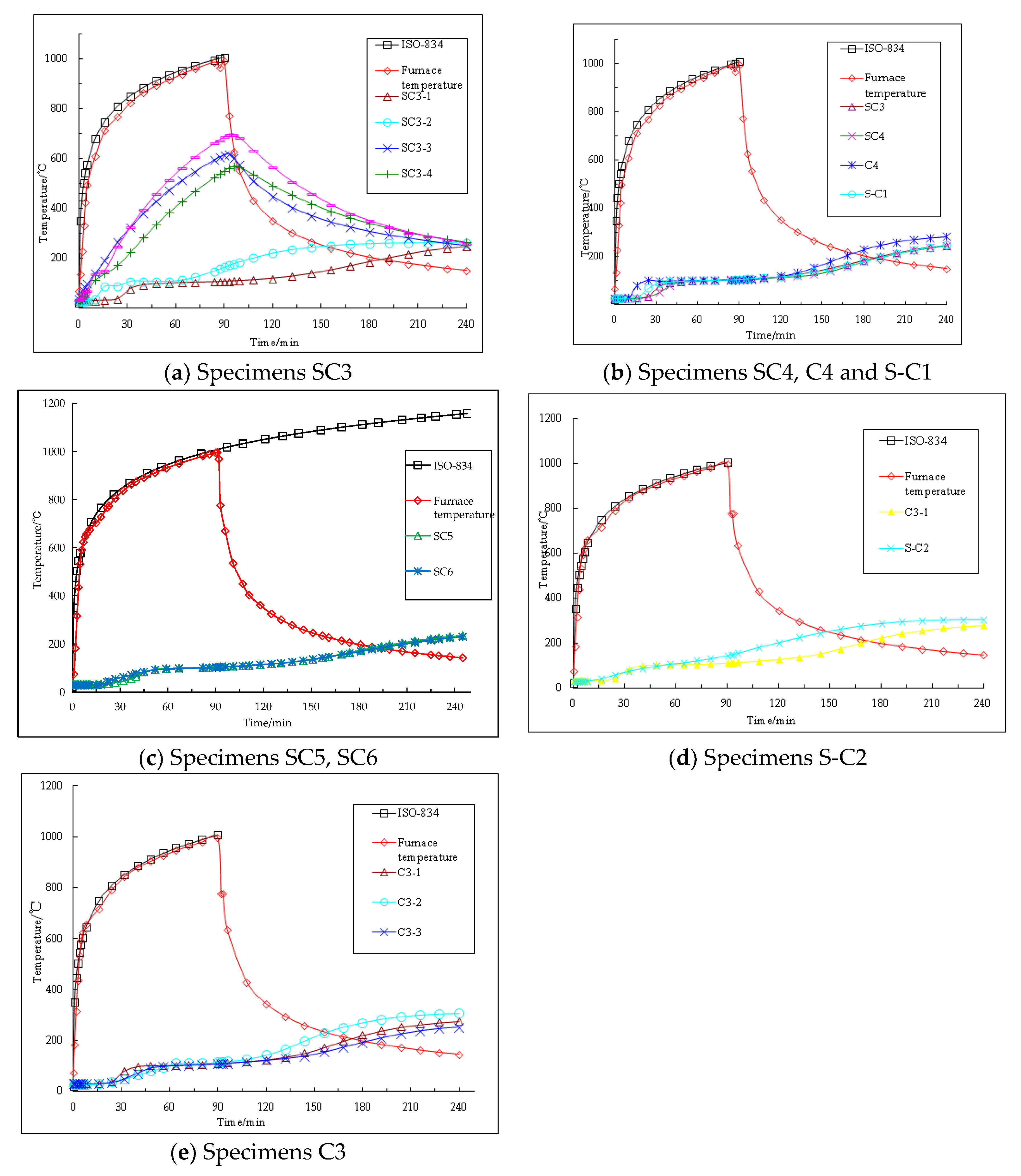
The fire test was carried out in the structural fire-resistance laboratory of the South China University of Technology. A large-scale horizontal component fire-resistant test furnace was used. The size of the furnace was 4 × 3 × 1.65 m. The gas used was fuel, and 12 combustion nozzles were evenly arranged on both sides of the north and south. After ignition, the measurement was carried out by using the sheathed thermocouple. The gas temperatures at 10 different locations in the furnace were recorded and averaged as furnace temperature. During the fire test, the temperature control and data collection were all carried out by computer. The heating curve was adopted following the building fire standard heating curve specified in China’s “Fire-resistance tests elements of building construction (GB/T9978-2008)” [
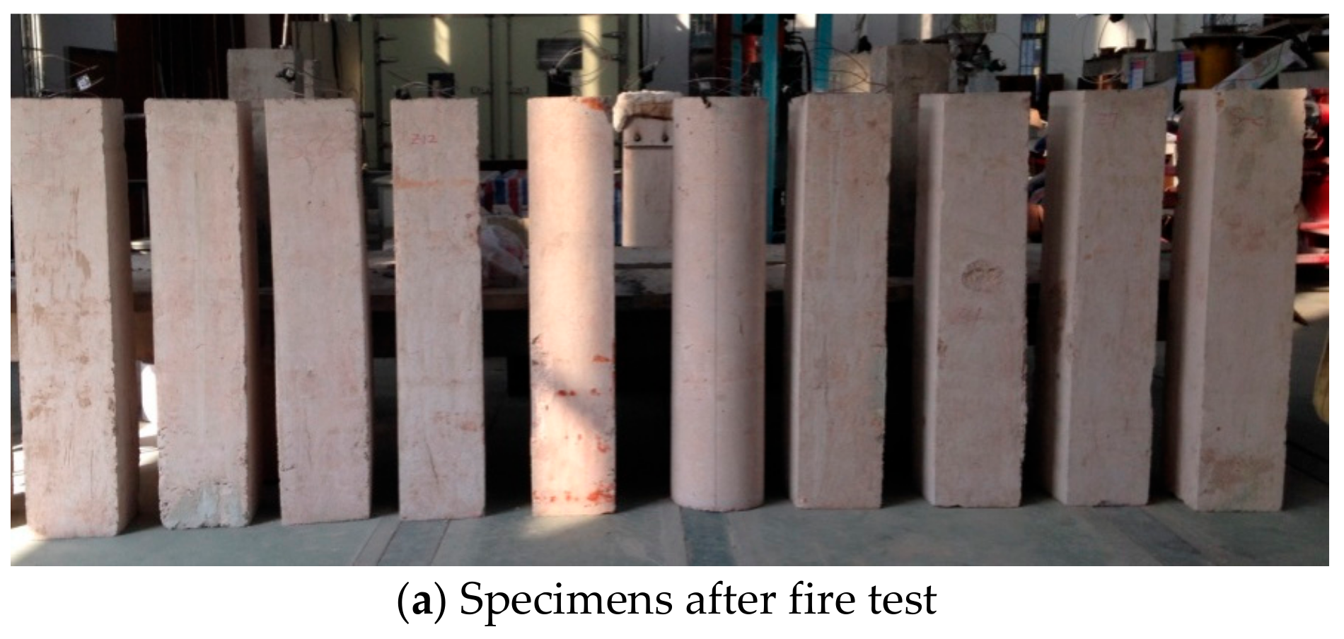
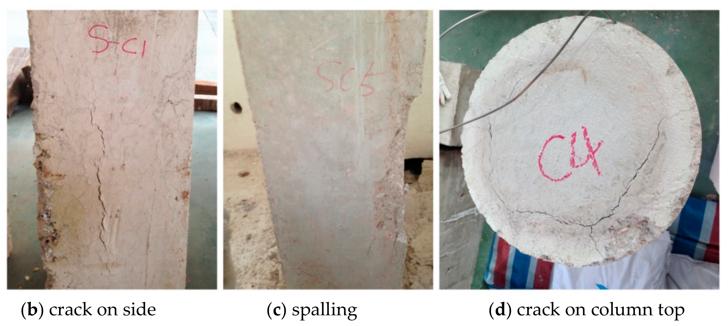
12]—the ISO834 standard heating curve. The temperature distribution inside the column during the heating and cooling process was measured using WRNK-101D3 armored thermocouples, see
Figure 4 and
Figure 5a illustrating the test specimens after the fire test. In
Figure 5b, after the fire test, the concrete surface color of all the test specimens changed from ash to brown, and irregular micro-cracks appeared on the surface. The corners of some square columns were partially spalling in
Figure 5c, and a significant ring crack at the upper end was observed, as shown in
Figure 5d.
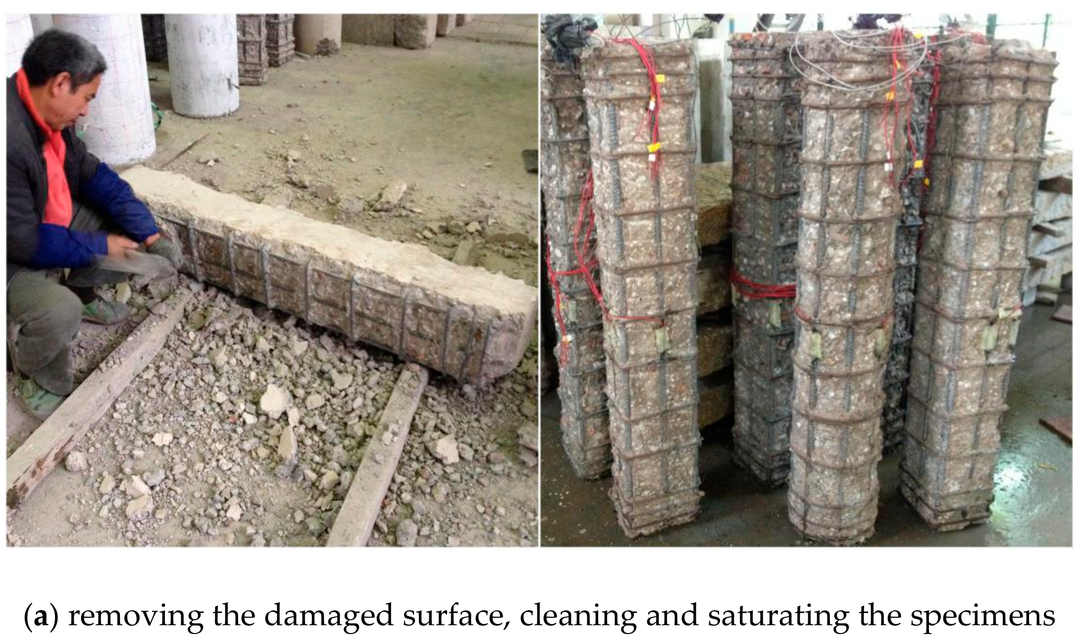
2.4. Strengthening Using Thin-Wall Tubes
The surface of the RC column was seriously damaged after exposure to fire. The first step of surface preparation was to remove a 30 mm thick damaged surface. Then the surface of the specimen was cleaned and saturated, with no treatments on the reinforcing bars. Finally, the specimen was wrapped by the steel tube, the gap was filled by C50 free flow non-shrink grout, to ensure that all parts achieve a good combination. Due to the narrow gap between the tube and concrete, to prevent a broken column, the grout was not infilled too much at signal pouring. The external wall of the steel tube was tapped with a hammer to check whether the gap was infilled or not. The grout was filled slightly above the upper end of the steel tube. The surface was levelled after curing, then the epoxy resin glue was evenly applied. The column was aligned with the geometric center of the upper end plate section. After the end plate and concrete surface were tightly combined, the test specimens were inverted, and the steel tube and the end plate were welded together. In the strengthening mode A, a circular strip of 15 mm wide was cut at 150 mm distance from each end of the tube. The strengthening procedure of the specimen is shown in
Figure 6.
2.5. Axial Compression Test
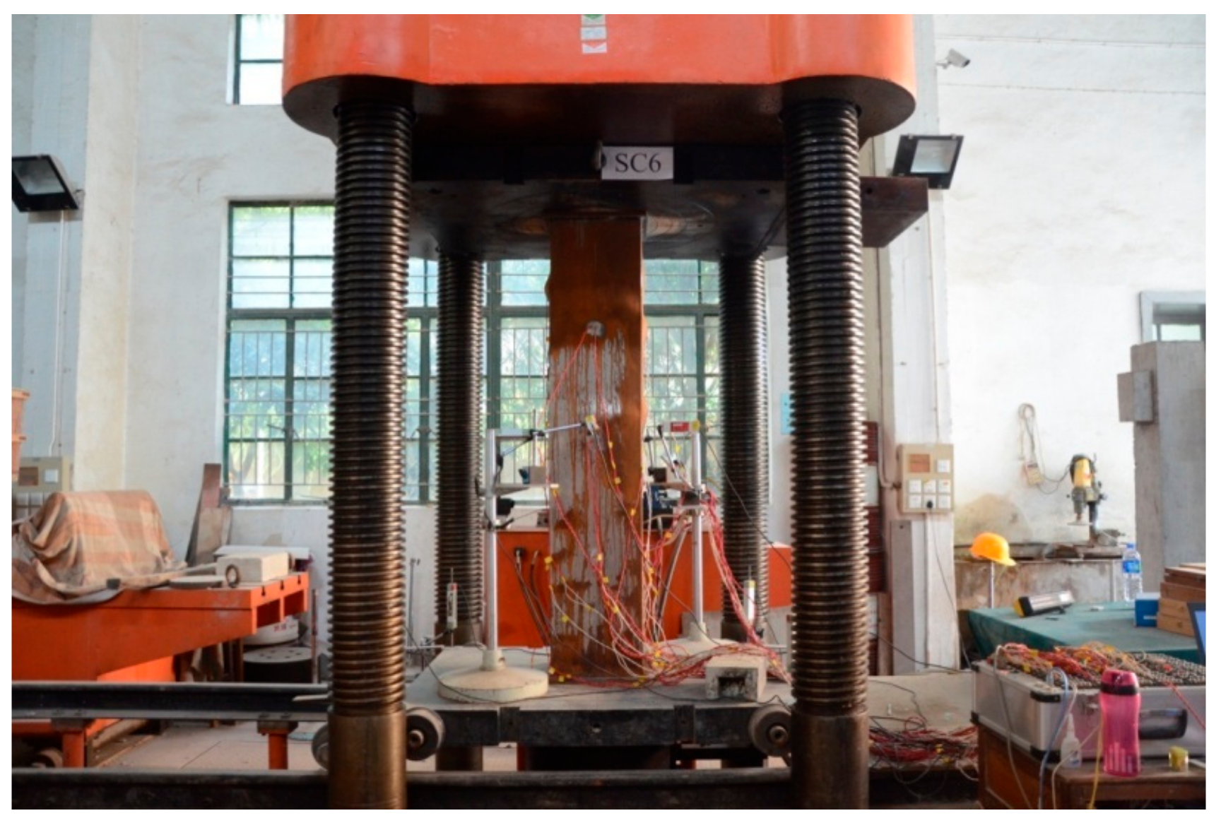
The test was carried out by a 10,000 kN electro-hydraulic servo compression shear test machine. The loading test was divided into two stages: Preloading and formal loading. To obtain the load-displacement curve, including the de-loading process accurately, the displacement control was adopted in the late stage of the loading test.
The preloading was subsequently divided into three levels. In each level, 5% of the estimated ultimate load was added. In formal loading, the load was carried out by increasing the load until 80% of the estimated ultimate load. The loading increase at each stage was 10% of the estimated ultimate load. When loading reached 80% of the estimated ultimate load, the test was carried by increasing the displacement, the load increase per stage was changed to 5% of the estimated ultimate load, and the loading rate was 0.5 mm/min. Each load stage was maintained for at least 3 min after the previous loading, until the loading drops reached 60% of the measured limit load, then loading was stopped. The loading device is shown in
Figure 7, and the lower steel plate is placed above the ball joint and can be rotated during the loading process. The hydraulic cylinder was located under the testing machine. The upper steel plate remains stationary during the loading process, and the lower steel plate moves upward.
The axial and transversal deformation were measured by using displacement gauge. The strain of the steel tube and the steel bar were measured by strain gauges. The force, displacement and strain signals during all loading were recorded by a DH3816 data acquisition instrument.
The arrangement of the displacement meters is shown in
Figure 8.
A electrical strain gauge was used to measure the strain of the steel bar. The longitudinal rebars were measured by 3 × 5 mm electrical strain gauges, and 2 × 3 mm resistance strain gauges for stirrups. Except for SC1 and C1, on which strain gauges were pre-installed, most specimens to be subject to fire had strain gauges installed after fire. The strain gauges were uniformly arranged on the stirrups of the middle section to monitor the lateral expansion during the axial compression. Four strain gauges were arranged on the unenhanced test specimens, and two strain gauges were arranged on the enhanced test specimens. The arrangement positions of the strain gauges for steel RC columns are shown in
Figure 9a–d.
Steel tube strain was measured by 3 × 5 mm electrical strain gauges. Four pairs of longitudinal and transverse strain gauges were pasted in the middle section, and four transverse strain gauges were attached to the steel tubes near the upper and lower annular strips on the test specimens enhanced by method A. For the test specimens enhanced by method B, divided into the upper, middle and lower three measuring sections, four pairs of longitudinal and transverse strain gauges were respectively attached to the steel tube. The arrangement of the steel tube strain gauge is shown in
Figure 10.
3. Result Discussion
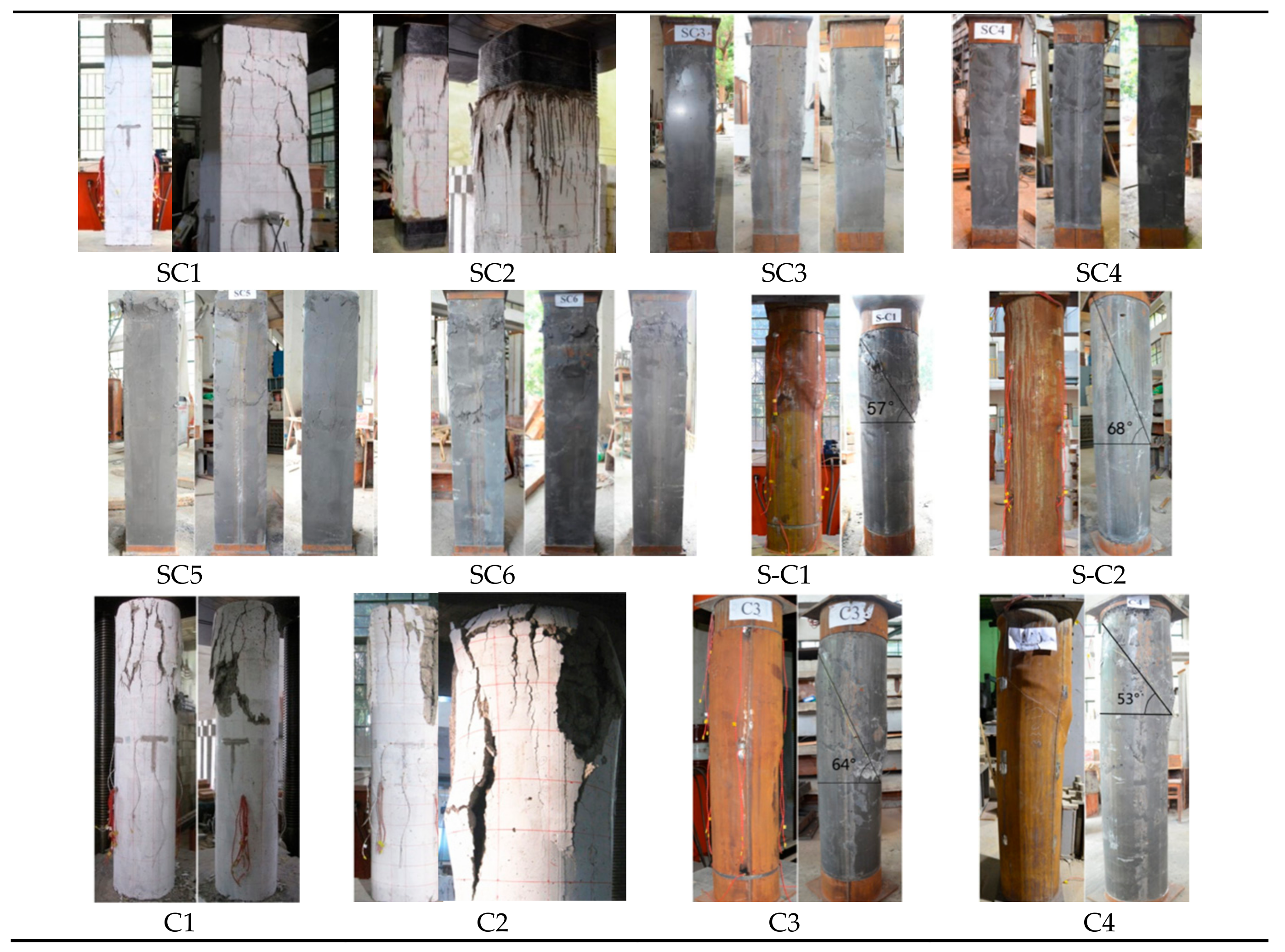
The failure modes of each test specimen are shown in
Figure 11. It is observed that when the thin-walled circular steel tube was subjected to the ultimate load, a diagonal crack of about 50 degrees to horizon occurred in the concrete, and then the steel tube was inclined and failed by shear. While the thin-walled square steel tube RC column was buckling, the column reached the ultimate load. After steel tube was cut off, the concrete near the buckling was crushed, and the other parts were not damaged.
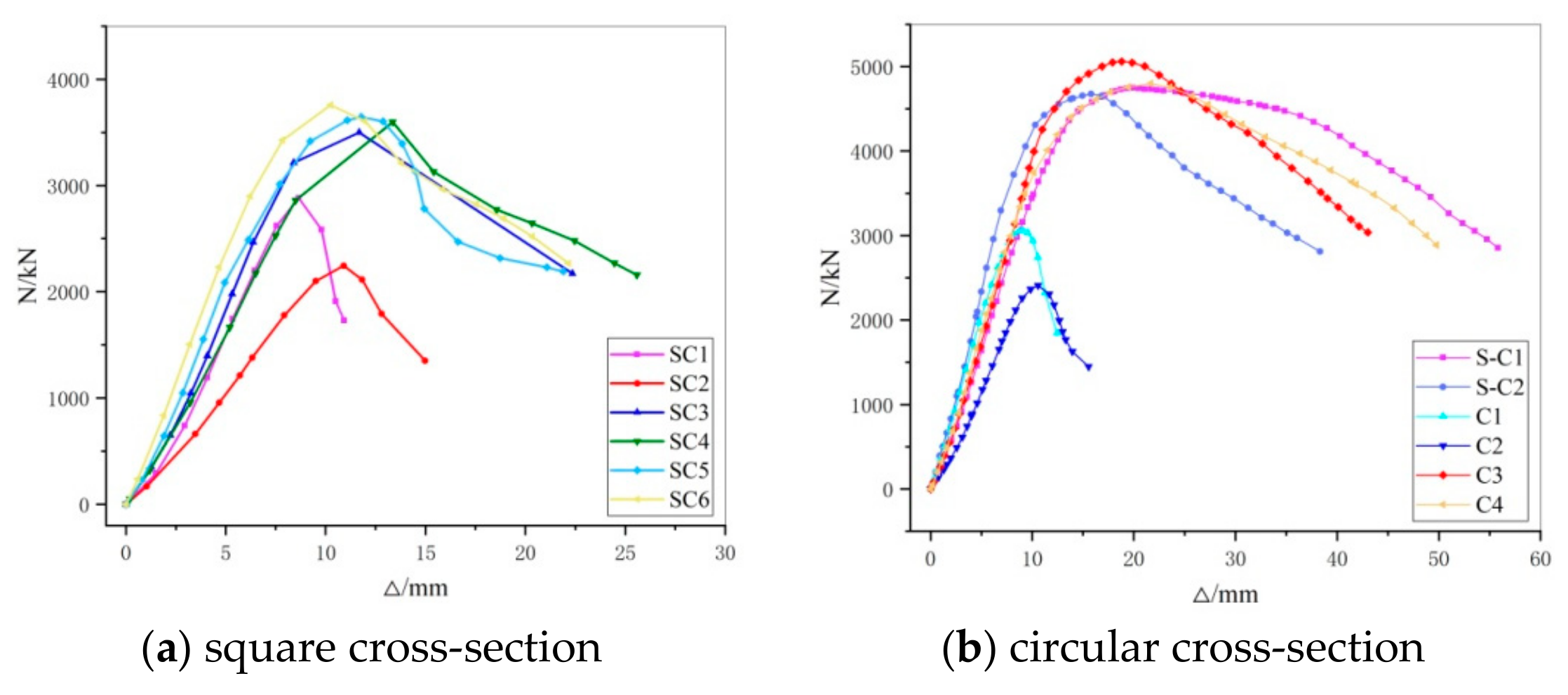
Table 4 gives the main characteristic points and test results of the post-fire RC columns strengthened using thin-walled steel tubes. All specimen N-Δ curves are given in
Figure 12a,b.
From the experimental observation and data, the main findings are summarized as follows: (1) The failure mode of the post-fire RC square column wrapped by a thin-walled square steel tube is the local bulking, and the column wrapped by the round steel tube failed by shear. (2) The test specimens appear to be “softened” after fire, with decreased axial stiffness and strength. The axial stiffness, axial compressive strength, and deformation capacity of the post-fire RC columns are significantly improved in strength by the thin-walled steel tubes. (3) Within the range of designed tube thickness (2 and 3 mm), the axial strength of the RC square column wrapped by the thin-walled square steel tube increases with the thickness of the tubes. (4) Different strengthening modes have no significant difference on the axial strength of the enhanced elements, it is more sensitive to axial deformation. Except the C3 specimen with a damaged welding, the rest of the specimens enhanced using mode A have larger axial deformations than the specimens enhanced by method B. (5) For the square column, the axial strength and the axial compression deformation of the columns whose cross-section were changed to a circle after strengthening are larger than those which remained as square cross-sections.
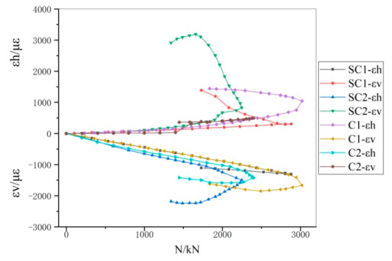
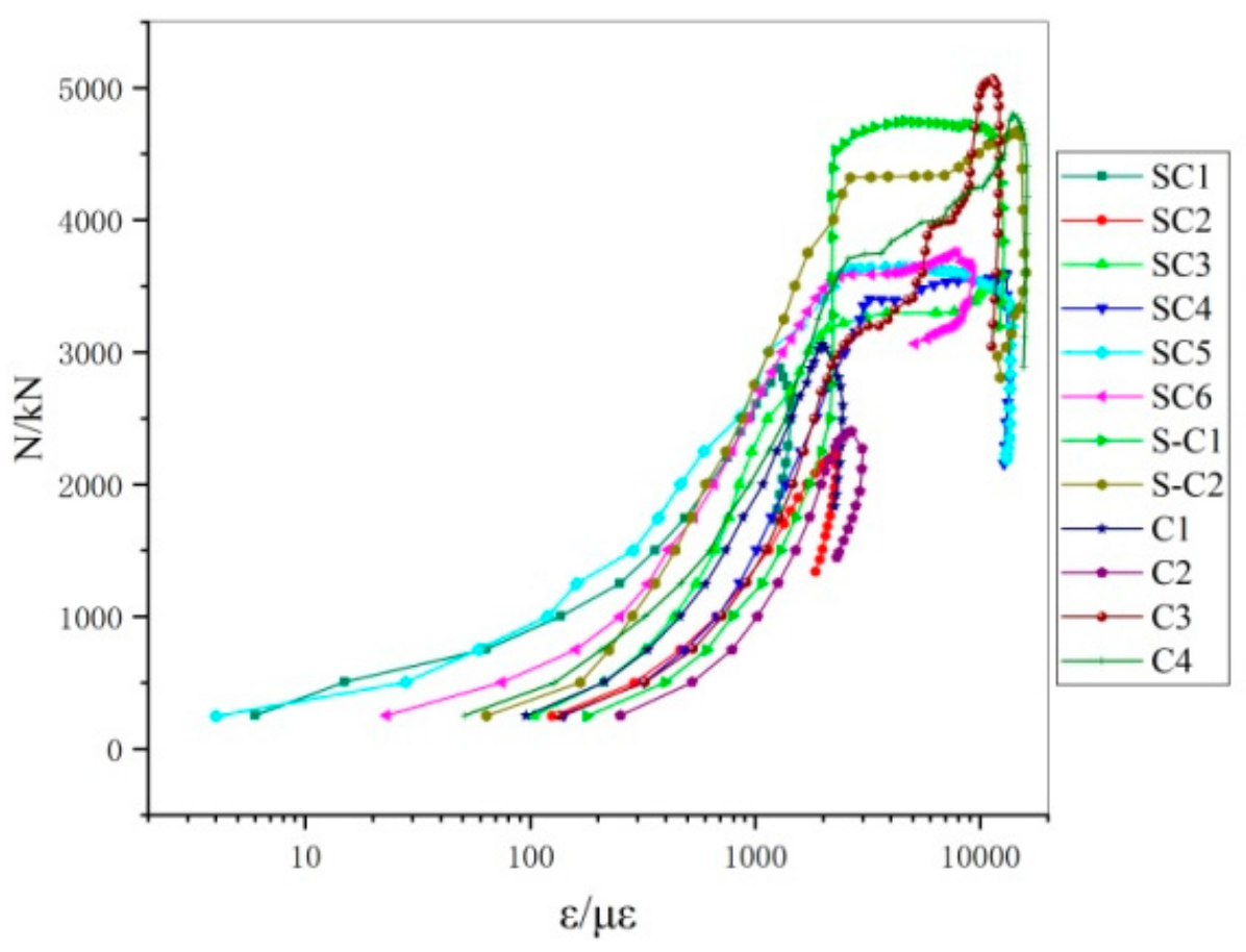
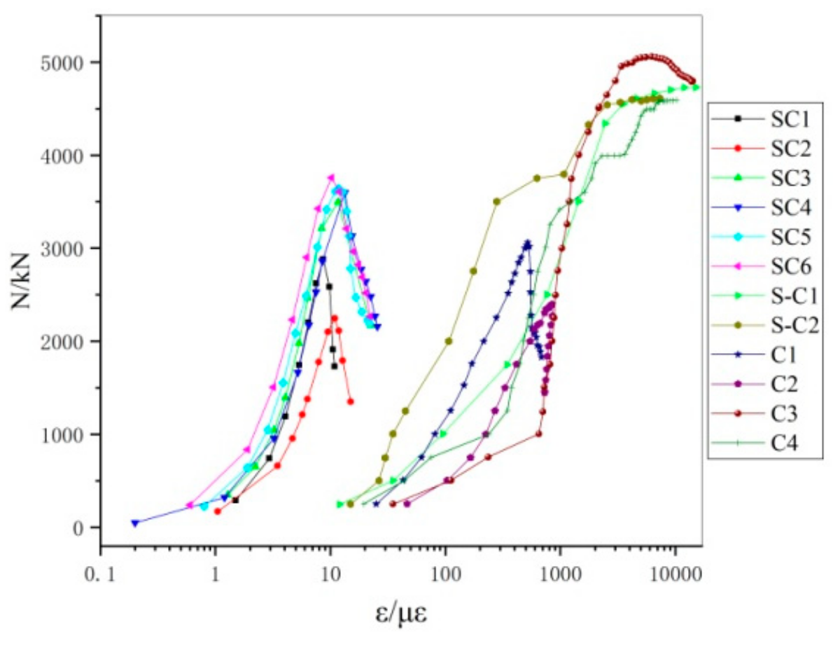
Eight strain gauges were installed at 1/2 height of the test specimen, and the average longitudinal strain and shear strain measured under the same load denote as
and
.
Figure 13 compares the load–concrete strains of the unconfined test specimens;
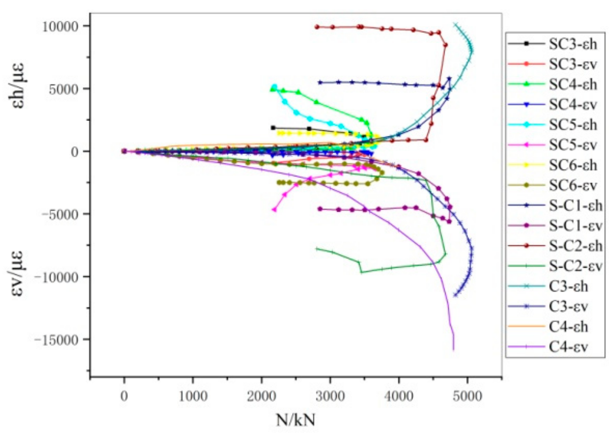
Figure 14 gives the load–steel line strain of the strengthened test specimens.
Figure 15 shows a longitudinal load–strain diagram of test specimens; and the load–strain diagram of the stirrup is shown in
Figure 16.
It is observed from the
Figure 13,
Figure 14,
Figure 15 and
Figure 16 that (1) the behaviors of the steel tubes are greatly affected by the enhancement methods. The steel tubes using strengthening mode A, which is merely subjected to circumferential strain, almost in belt tension and provide a strong restraint to the core concrete. The tubes using strengthening mode B, are mainly subject to compression, which are likely to buckled under with a resulting strain along the longitudinal direction. (2) The middle part of the square tube for strengthening yielded until the ultimate strength, and the middle part of the circular tube yielded before the ultimate strength was achieved. Compared with the square steel tube, the circular tube can achieve better material efficiency of the steel, with larger axial strength and axial compression deformation value. (3) The longitudinal reinforcement and stirrup of the strengthened specimen yielded before the ultimate load. Then most of the reinforcements are in post-yield stiffening status, indicating that the test specimen obtained good ductility after enhancement.
3.1. Analysis Method on the Structural Strength
The experimental research indicates that the confining coefficient of a thin-walled circular steel tube wrapping a concrete column is very small, and shear failure occurs under axial compression. The thin-walled square steel tube concrete column failed by buckling.
In the calculation of the axial strength of the post-fire RC column strengthened using thin-wall tubes, the following assumptions are made:
(1) The strengthened component still conforms to the Bernoulli hypothesis of flat sections.
(2) The post-cast concrete, the original concrete after the surface treatment and the steel tube, can be effectively bonded together, and no interface slip occurs before the ultimate strength is approached.
(3) The confining effect in the original column from the stirrup is small and negligible.
(4) The concrete section of the original column after high thermal action is assumed to be an equivalent cross-section of uniformed strength. The temperature field of the cross-section column subjected to fire is determined [
13], and the uneven temperature field is simplified into an equivalent cross-section of uniform strength [
14], as Equations (1) and (2).
In the Equation:
—the cubic compressive strength of concrete after high thermal action;
—the cubic compressive strength of concrete in air temperature.
(5) The thin-walled steel tube is under a uniformly distributed load across the wall thickness, ignoring the radial direction stress along.
(6) When the column reaches the ultimate axial strength, the lateral stress of the thin-walled steel tube is assumed to reach the yield strength .
3.2. Post-Fire RC Column Stengthened by Thin-walled Circular Steel Tube
Assuming that when the specimen reaches the ultimate axial strength, the longitudinal stress of the wrapping steel tube is zero, and the hoop stress reaches the yield strength of the steel. At this time, the wrapping steel tube provides maximum restraint on the core concrete.
Considering the influence of the high temperature on the strength of concrete and steel, and the enhancement of the core concrete by the thin-walled circular steel tube, the ultimate strength of the RC column
consists of the confined concrete strength and the longitudinal reinforcement strength. The equation as follows:
where
is the constrained concrete axial compressive strength [
15]. According to the Willam–Warnke failure criterion [
16] of the concrete under uniformed lateral stresses, the equation of the concrete strength is given as
where
is the axial compressive strength of unconstrained concrete;
is uniformed pressure, i.e., the restraint stresses on the concrete; calculated following Equation (5)
where
is the yield strength of the wrapping steel tube; D is the cross-sectional diameter of the strengthened specimen;
is the wall thickness of the wrapping steel tube;
is the cross-sectional area of the core concrete;
is the cross-sectional area of the No.
longitudinal reinforcement in the original column;
is the yield strength of No.
longitudinal reinforcement in the original column after exposed to fire, using the temperature field during the fire test, reduced according to the literature [
17].
The axial compressive strength of the unconstrained concrete in the strengthened test specimen is taken as the combined strength of the concrete exposed to high temperature, and post-cast concrete, as Equation (6).
where
and
denote the cross-sectional area of the post-fire concrete after removing damaged concrete outside from the longitudinal reinforcements and the concrete axial compressive strength after the high temperature, respectively;
and
denote the cross-section area of the newly poured concrete and its axis compressive strength, respectively.
The comparison between the test results
and estimate values
from Equation (3) for the axial strength of enhanced RC column is shown in
Table 5. The calculated results match well with the test results, indicating that Equation (3) can be used as a reference for the strengthened post-fire specimen design.
3.3. Post-Fire RC Column Enhanced by Thin-Walled Square Steel Tube
The force model shown in
Figure 17 [
18] indicates that the square steel tube exerts non-uniform constraints on the core concrete, and can effectively restrain the corner and cross-section center of the concrete, but not the edge part between the corners. In
Figure 17, b is the side length of the core concrete. The concrete within the range of 0.1 b from the corner is the zone under boundary confinement, and the concrete in the range of the edge 0.8 b is the unconstrained zone, and the curve of the unconstrained zone is a quarter circle. The shaded parts in the figure are unconstrained areas. The calculation based on the geometry indicates the effective confinement area of the core concrete is 63.5% of the total cross-sectional area, and the effective constraint coefficient of the defined square steel tube to the core concrete is
In the equation, is the effective confined area of the core concrete; is the cross-section geometry of the concrete.
The effective constraint stress of the square steel tube to the core concrete
is obtained by the effective constraint coefficient:
where
is the restraint stress of the square steel tube on the core concrete, calculated following Equation (9).
where
denotes the yield strength of the wrapping steel tube;
b denotes the cross-section side length of the specimens; and
denotes the wall thickness of the wrapping steel tube.
According to William’s five-parameter failure criterion of concrete under uniformed lateral stresses, the core concrete strength inside the thin-walled square steel tube is given as
The effective confined area of the core concrete is basically the cross-section of the specimen after removing the damaged surface, and the unconstrained area is the newly poured concrete section after strengthening. In order to simplify the calculation without compromising it significantly, the cross-section of the specimen removed from the damaged surface is defined as the effective constraint zone, and the newly poured concrete section is assumed to be the unconstrained zone. The axial strength
of the RC column wrapped square steel tube consists with the strength of confined concrete, unconstrained concrete, and the longitudinal reinforcement strength. Equation (11) is as follows:
where
denotes the axis compressive strength of the RC column enhanced using a square tube, according to the Mander model [
15] (see Equation (4)); The computed axial strength of the enhanced post-fire RC columns with square sections and the experimental results are shown in
Table 6.
3.4. Comparison and Validation
In China and other countries, there are many design standards [
19,
20,
21,
22,
23,
24,
25,
26] and research [
27] on the axial strength calculation of concrete filled steel tubes.
In order to investigate whether the existing calculation methods of concrete filled steel tubes are suitable for the post-fire RC columns wrapping thin-walled steel tubes, in accordance with JCJ01-89 [
19], CECS28:90 [
20], DL/T5085-1999 [
21], DBJ13-51-2003 [
22], ACI318-08 [
23], AIJ-1997 [
24], EC 4-2004 [
25], GJB 412-2000 [
26] and other literature [
27], the axial strength of the circular specimens and the square specimens were calculated, as shown in
Table 7.
In retrofit specifications, the strength calculation method of the CFST axial compression short column is used to calculate the axial strength of the post-fire RC column wrapped thin-walled steel tube. In JCJ01-89, the strength of columns with different slenderness ratios can be calculated by adjusting the stability factor of the axial compression column. In CECS28:90, the reduction factor of the slenderness ratio and the eccentricity of the component are taken into account, and the ferrule coefficient of the reinforced concrete is used to modify the calculated value. In DL/T5085-1999, DBJ13-51-2003, and GJB 412-2000, the design value combined with the steel tube concrete axial strength is used. In ACI318-08, the concrete-filled steel tube is simulated to equivalent reinforced concrete elements to calculate the structural strength. EC4-2004 is commonly used for the strength of the concrete wrapped by steel tubes of square, circle and rectangular shapes. The constraint from the circular steel tube onto core concrete is taken into account. The design code in both China and other countries are proposed mainly for ordinary concrete-infilled steel tubular columns. The strengthening elements on post-fire RC in this research are thin walled tubes. The enhanced column strength developed in this paper, was compared the design values calculated in accordance with ACI318-08 [
23], then verified by the test results. The calculated results of DBJ13-51-2003 and AIJ-1997 agreed with the test results of average variations—5.8% and −3.8%, respectively. As shown in
Table 7, the calculations following the Chinese Standards and ACI318-08 [
23] seem higher than the test results because the formulas specified in the national codes are generally developed based on a consistent theory, considering the constraint effects of steel pipes on concrete. In the US code, Eurocode, and Japan code, superposition theory is generally adopted, and concrete strengthening from the steel tubes is not considered, therefore the calculated design resistance in accordance with the codes are lower than the experiment results.


