Abstract
This paper describes an integrated control strategy that utilizes semi-active suspension and differential braking to enhance lateral stability while maintaining roll performance. The integrated control architecture adopts a hierarchical structure consisting of an estimator, a supervisor, a controller, and an allocator. In the estimation layer, an algorithm is proposed to robustly estimate the side slip angle and roll angle in various situations. The control mode is established by the supervision layer based on the state of the vehicle. The maneuverability mode tracks the driver’s intentions, and the lateral stability mode ensures the vehicle’s stability. Reference values such as yaw rate and roll angle are determined by the control mode. In the controller layer, the yaw and roll moments are generated using sliding mode control to achieve the target yaw rate and roll angle. Brake torque and suspension damping force are distributed to each wheel in the allocator layer. In particular, a damping distribution method based on the roll region index is proposed. The proposed method is compared with conventional methods, such as full stiff damping and yaw-assisted damping, through simulation and real-world evaluation. The tests demonstrate that the proposed approach enhances lateral and roll stability, particularly regarding maximum side slip and roll angle values. The roll-region-index-based distribution method reduces the maximum roll angle by about 17.4% and the maximum side slip angle by about 8.7% compared to each conventional method. Compared to conventional methods, the proposed method showed more stable driving performance by ensuring stability in both directions in extreme lane change situations.
1. Introduction
The trend of mobility has been rapidly shifting toward autonomous driving and electrification. The electrification of not only the drivetrain but also the chassis system, which determines the vehicle’s dynamic behavior, is also developing quickly. Motor-based electrification of the chassis has the advantage of accurate control response, and modularization of the system enables independent operation of each actuator. Furthermore, the development of autonomous driving enables more information to be used for chassis control. Therefore, future chassis control should optimize the performance of vehicle systems with multiple actuators by using various inputs. Conventional chassis systems generally operate independently, with one function targeting a single dynamic direction. Such an independent chassis control has difficulties in the cooperative control of multiple targets. In addition, as the number of actuators increases, there is a limit to the allocation of control to optimize overall performance. In other words, downstream-based independent control has limitations in optimizing the vehicle’s overall performance. Therefore, recent studies of integrated chassis control adopt a control mode selection method or a centralized, hierarchical control architecture that aims to improve the overall dynamic performance by coordinating multiple chassis systems [1].
In previous studies of hierarchical integrated control, much of the research was based on control mode switching. Braking and steering, which can directly affect the vehicle, were widely used to improve lateral performance, such as maneuverability and lateral stability. The authors of [2] used hierarchical structure-based control using active front steering control (AFS) and electronic stability control (ESC). This was achieved by switching between maneuverability and stability modes depending on the control mode. The authors of [3] set the nonlinear index of an AFS with direct yaw moment control according to the stability region, distributing target yaw moments to the brakes and steering.
On the other hand, the suspension control was similarly control-mode-based and mainly focused on the vehicle’s ride comfort or tire grip on the ground. Some suspension control based on the control mode was configured using a rule-based method. The authors of [4] divided the control mode into six finite states and preset whether the brakes function was engaged and the gain of the suspension accordingly. In this case, the suspension uses the preset PID control gain for each mode. The authors of [5] assigned the desired moments to the suspension via a weighting coefficient in the upper controller, which is then distributed via optimal control. The weighting coefficient is pre-selected with an appropriate value through trial and error. The authors of [6] distinguished between ride comfort and stability modes based on steering angle and lateral acceleration and configured a rule-based fuzzy control logic accordingly. The above fuzzy logic is activated simultaneously with the brakes, but the suspension’s control method is tuned in advance. In a recent study, suspension control is performed in control modes that target tire-to-road adhesion or ride comfort [7]. The study, considering the independent drive, presented an integrated control scheme combining an active suspension system and a brake system for a four-wheel independent-drive electric vehicle [8]. As shown above, the suspension control method has been preset for different situations and mainly controls the tire grip and roll stability. These conventional methods are considered as full hard damping methods in this study because they stiffen the suspension for attitude control.
Next, the suspension control method of influencing the vehicle’s yaw moment using the load transfer of the tire’s front and rear wheels was studied. The author of [9] used differential brake, suspension damping control, and active roll control to improve lateral stability and roll stability by regulating the vertical force on the tires through the suspension to influence lateral behavior [9]. The author of [10] divided the control of an MR damper into maneuverability control and attitude control modes depending on whether it is cornering or in a straight line. In this case, the maneuverability mode of the MR damper uses the tire’s load transfer to the front and rear wheels. These conventional methods correspond to the yaw assist method by damping control in this study.
In a recent study on semi-suspension, especially for multiple directions, attitude control in three directions, such as yaw–roll–pitch, was optimized using weight adjustment through suspension damping control [11]. However, even in this study, assisting in one direction comes at the expense of the other’s performance. In other words, within the identical control mode, one direction must be sacrificed to assist another direction. While these existing studies are based on switching control modes to achieve the proper suspension control mode for different situations, there is a trade-off between yaw assist performance and roll performance in semi-active suspension. This issue becomes more problematic in extreme situations because both lateral and roll performance are required in severe conditions.
This paper notes that the yaw assist method, which uses front and rear load transfers, only considers models of the relationship between the tire and the ground. The real-world evaluation of the previous yaw assist method showed that even the negative control method improved the lateral stability performance under some conditions. This means that the vehicle’s lateral behavior is influenced not only by the relationship between the tire and the ground but also by the change in the sprung mass as the damping softens. Based on the movement of sprung mass, this study proposes a method for improving roll and lateral performance by controlling damping according to the roll region index without switching the control mode. Especially in extreme conditions where lateral stability is required, such as sudden lane changes, the attitude of the vehicle also becomes important. In previous studies, this was solved by changing the control mode. This study shows that the roll region index improves roll performance in the same control mode without switching control modes.
The validity and effectiveness of the proposed method are verified through simulations and real-world tests. The test results show the limitations of conventional methods, such as full stiff damping and yaw assist, and confirm that the proposed method significantly improves performance in both directions.
In addition, this study considers some physical models linearly to demonstrate the method but, in the future, nonlinearities can be addressed to improve performance further. For example, the control performance can be improved in the suspension using a nonlinear dynamics model fluid inertia-based suspension model [12]. In addition, the tire model’s cornering stiffness is also assumed to be linear but, in sudden lane changes in actual conditions, the tire force shows nonlinearity. In this study, a roll model assuming linear stiffness and damping is used, and a lateral and yaw model with a linear tire model is applied. However, the model error is compensated by a sliding mode control that is robust to nonlinearity. The above assumptions did not affect the performance of the proposed control method when the appropriate linear coefficients were used for the limited conditions in the real-world evaluation. However, it should be considered that nonlinearities are necessary for applying the proposed algorithm commonly under various conditions. Note that this study focuses on the hierarchical control structure and the description of the suspension control distribution method through the roll region index, which is assumed to be linear for simplicity.
Section 2 describes the overall control mode with a flow chart. Section 3 expresses how to robustly estimate the vehicle’s state variables for integrated control. Section 4 and Section 5 describe the implementation of control-mode-based integrated chassis control in this work. Section 6 describes the logic by which yaw assist control by damping is implemented by distributing the yaw and roll moments obtained through the controller. Then, in Section 6.2.2, the suspension damping method using the roll region index is presented. Section 7 discusses evaluation results obtained by simulation and real-world tests. Finally, Section 8 presents the conclusions, limitations of this study, and future work.
2. Overall Control Scheme
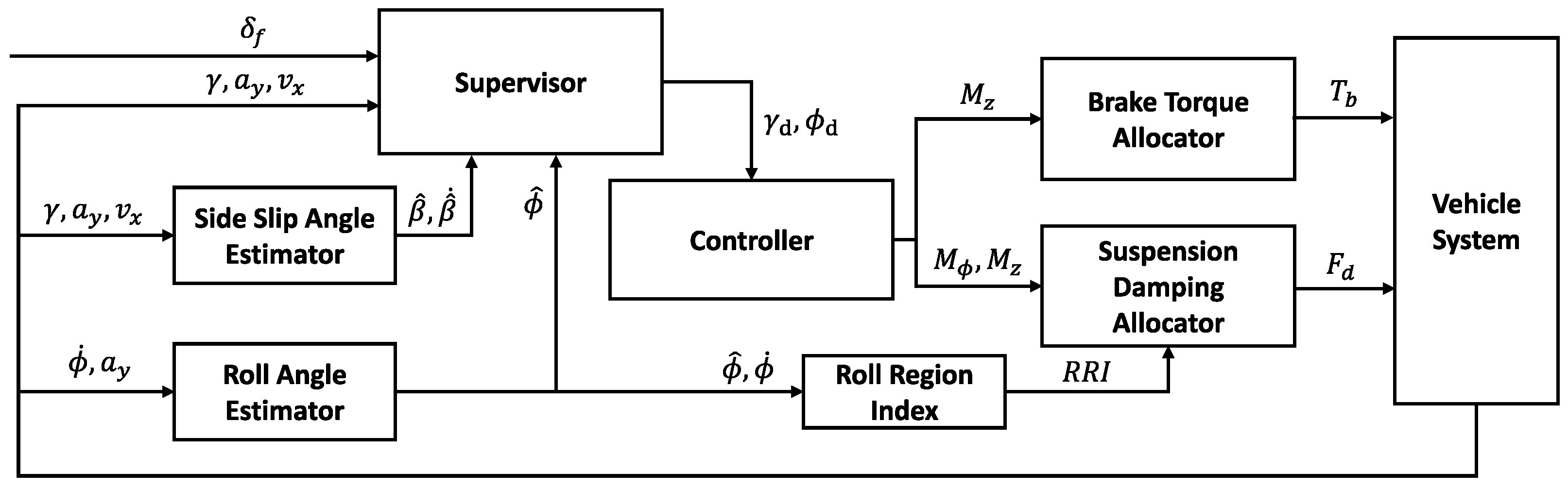
The hierarchical architecture is used for integrated control of suspension and brake, as shown in Figure 1. This structure maximizes the dynamic performance of integrated control and allows for scalability and flexibility, which are advantages of a centralized processing architecture. The integrated control structure is composed of four layers. The first layer is the estimator, responsible for estimating information about the vehicle’s state. An accurate and robust vehicle state estimation is important because driving mode decisions and control amounts are determined based on estimated values. In other words, precise state information is required for the other layers to generate the appropriate reference and control. The second layer is the supervisor, which determines the vehicle’s control mode and reference motion. In this step, the control mode is determined by various parameters, and the reference value is changed according to the control mode. For example, maneuverability mode generates a reference value that aims to follow the driver’s steering intentions, and lateral stability mode creates a reference that aims to increase the vehicle’s lateral stability. The third layer is the controller, which determines the global vehicle input, such as the force and moment of the vehicle. In this study, the yaw moment and roll moment are determined by sliding mode control to ensure robustness against nonlinear characteristics. Lastly, the fourth layer is the control allocator. This layer distributes the appropriate amount of control to each chassis system based on optimal distribution. In addition, a distribution method using the roll region index is presented. Compared to conventional suspension control, this method improves performance in both the roll and lateral directions.
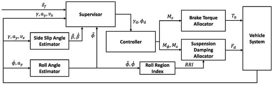
Figure 1.
Overall control scheme.
3. Estimator Layer
Integrated chassis control requires an accurate estimation of the state variables, but some values are difficult or expensive to measure with commercial sensors. For example, the side slip angle is the difference in angle between the vehicle’s direction of travel and its heading angle. It is used as an important factor in the vehicle’s lateral stability. However, obtaining accurate side slip angles directly from commercial sensors is complex and requires additional devices, such as a global positioning system and image sensor, which increases cost. This paper needs the roll and side slip angles to control lateral and roll stability. In general, when estimating the roll angle, uncertainties in the vehicle’s rotational stiffness, damping coefficient, and changes in the vehicle’s center of rotation cause errors from the model to the actual outcome. In addition, the nonlinearity of tire force decreases the accuracy of the side slip angle estimation. Therefore, it is necessary to improve the precision of the modeling and design a robust estimator of uncertainties for reliable estimation. In this study, a sliding mode observer based on the sliding theory is adopted, and a Kalman filter with a kinematic model is used to improve the performance of the side slip angle observer.
3.1. Design of Roll Angle Observer
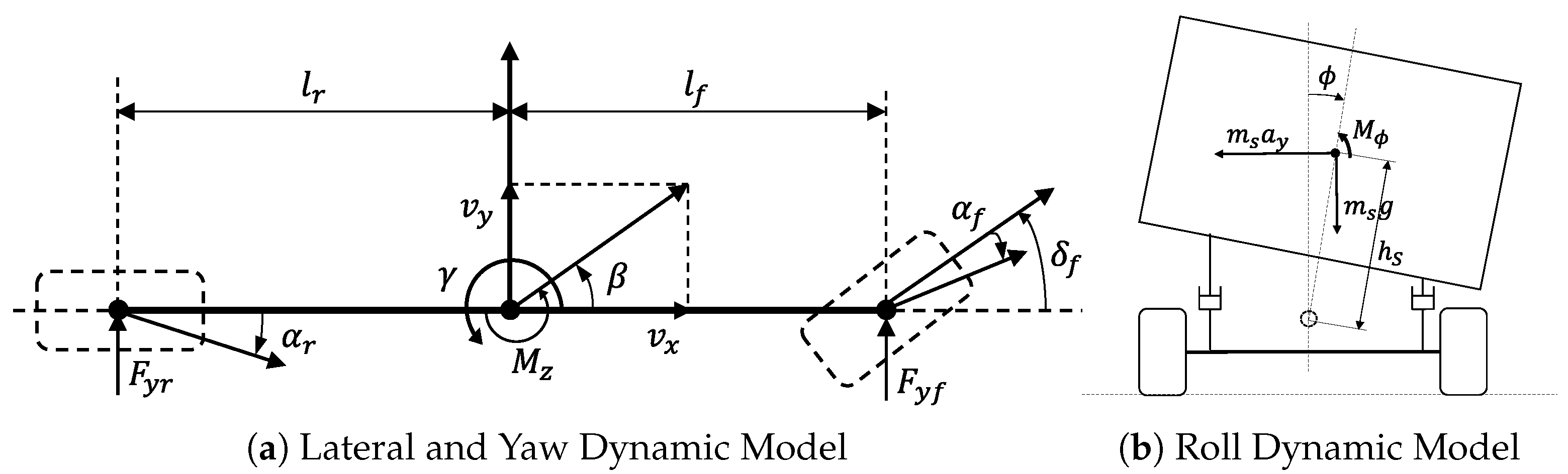
As illustrated in Figure 2b, the vehicle’s roll dynamics are represented as follows:
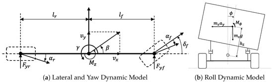
Figure 2.
Dynamic model of vehicle.
When defined as a state vector , input vector , and output vector , Equation (1) can be rewritten as follows:
The Utkin observer is expressed by Equation (3).
The system is asymptotically stable when a Lyapunov function exists that satisfies Equation (4), and the sliding surface is defined as Equation (5).
To derive the error dynamics of the output, the augmented matrix is defined as follows:
In this case, is the null space of matrix C. If , the augmented system is represented by Equation (6)
Using Equations (3) and (7), the error dynamics can be represented as follows:
When , Equation (8) can be written as follows:
Finally, the output error for the dynamics for the estimated output error can be written as follows:
Thus, for any that satisfies , the output error converges to zero in finite time because . Finally, the observer of the roll angle is given by Equation (12).
3.2. Design of Side Slip Angle Observer
In previous research, side slip angle estimation can be broadly categorized into kinematics-based and dynamics-based estimation. Kinematic-based estimation can be obtained using the vehicle’s heading angle and yaw angle from the global positioning system and the internal measurement unit [13,14]. However, this method has good performance at high-speed changes, but errors in integration and the low update rate degrade estimating performance. On the other hand, studies on dynamics-based estimation have used observers such as a Kalman filter and sliding mode observer to estimate the slip angle based on dynamics models. These dynamics-based estimates are advantageous for the cumulative error and update rate, and because linear tire models are typically easily available, the performance of these estimates is good in linear domains such as low speed and smooth steering. However, the estimation performance decreases as the error between the model and the actual outcome becomes larger, such as the nonlinearity of the tire and the error with simplified models. Thus, nonlinear tire models and an unscented Kalman filter were used to improve performance in nonlinear regions [15], dimensionless coefficients were introduced to account for the nonlinearity of the tire [16], a 7 DOF vehicle model and longitudinal forces were considered to reduce model error [17], and estimation performance was improved using a combined model based on frequency with a kinematic model [18]. These studies can improve performance in extreme conditions but, in real applications, additional costs are needed to tune the nonlinear model and estimate other variables by a vehicle test. In this study, in order to develop an estimator with good performance without the above additional costs, a sliding mode observer based on a linear tire model and the rate of side slip angle derived from the kinematic model are combined using a Kalman filter to obtain a modified side slip angle. As illustrated in Figure 2a, the lateral dynamics of the vehicle are expressed as follows:
Using the lateral tire force and the tire slip angle, the equation can be expressed as follows:
The side slip angle of the vehicle is presented as follows:
3.3. Combined Model of Side Slip Angle Observer with Kinematic Model
The kinematic model and a Kalman filter are used to calibrate the estimation to improve the estimation performance of the nonlinear region of the tire. Since the kinematic model does not include the uncertainty of the tire, the side slip angle rate derived from the model has a relatively accurate value. However, when it is used as an integral, there are problems of error accumulation, and its performance is poor under noisy conditions. Therefore, using the beta rate of the kinematic model based on the sliding mode observer can construct a stable estimator that reflects rapid changes while compensating for the weaknesses of both methods. The beta rate obtained from the kinematic model is as follows:
The algorithm for the sliding mode observer and kinematic model using a Kalman filter is as follows. The predictive model of the side slip angle and its rate are represented in the discrete-time state space form as Equation (21).
where Q is the covariance matrix for system noise, R is the covariance matrix for the measurement noise, and H is the relationship matrix between the measurements and the state variable. With the Kalman filter, the side slip angle is updated every cycle time by the predictive state model, while the rate of change is blended with the value obtained from the kinematic model. This means that the proposed method accurately estimates the rapid change in the side slip angle by using the kinematic model, which removes the uncertainty of the model while ensuring the stability of the estimation error based on the sliding mode theory.
4. Supervisor Layer
In this layer, the control mode index is based on the vehicle state and the driver’s input. The reference yaw rate is determined by the control mode, ensuring that the vehicle behaves appropriately in each mode.
4.1. Control Mode
4.1.1. Maneuverability Mode
Maneuverability mode means that the yaw rate error becomes larger than a threshold and the vehicle does not follow the intention of the driver. The maneuverability index is defined as follows:
where is the vehicle yaw rate and is a yaw rate error criterion, which means the magnitude of the yaw rate error in which the entry is the control mode. If exceeds 1, it means entering the maneuverability mode, if it is positive, an understeer control is performed, and if it is negative, an oversteer control is performed.
4.1.2. Lateral Stability Mode
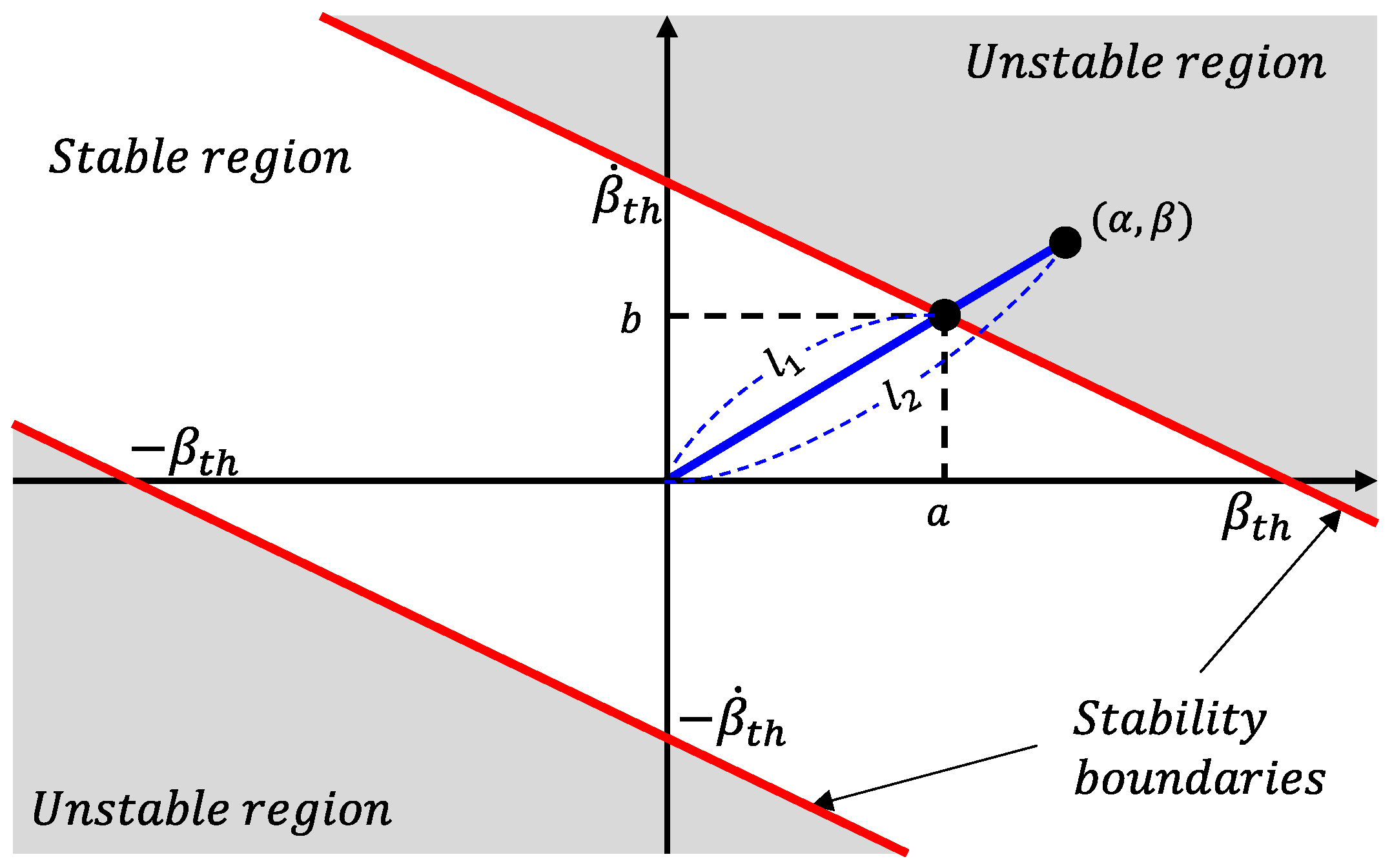
If a side slip occurs above a certain level, the side slip angle control is performed to ensure the stability of the vehicle. In general, it is known that the driver feels unstable when the side slip angle is more than 3 degrees. As shown in Figure 3, the stable and unstable regions can be distinguished according to the side slip angle and its rate.
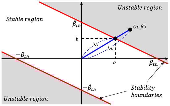
Figure 3.
Lateral stability mode.
The lateral stability mode index is summarized as Equation (23) and enters the lateral stability mode when the index is greater than 1.
4.2. Reference Value
In maneuverability mode, depending on the driver’s steering intention, the target yaw rate as a function of the steering angle is expressed as follows:
where are the distance from the center of gravity to the front/rear axle, are the stiffness of the cornering of the front and rear tire, m is the mass of the vehicle, and is the longitudinal velocity of the vehicle. In lateral stability mode, a reference yaw rate is derived that minimizes the side slip angle as represented in Equation (25):
To obtain a smooth transition between modes, a weight factor is defined as shown in Figure 4.

Figure 4.
Weight factor for reference yaw rate.
The final desired yaw rate is shown below.
The desired roll angle for ride comfort is defined as follows:
5. Upper Controller Layer
The upper controller determines the global control input of the vehicle, which determines the amount of control needed to obtain the desired yaw rate and the desired roll angle. The desired yaw moment and desired roll moment were determined using sliding mode control for robustness against tire cornering stiffness and vehicle state model error. The yaw dynamics of the vehicle and the uncertainty are expressed as follows:
where is the inertia of the yaw moment of the vehicle and is an additional yaw moment. The sliding surface needed to track the yaw rate is defined as Equation (29):
According to the Lyapunov direct theorem, the desired yaw moment needed to stabilize the system is given by Equation (30). The system is asymptotically stable if the value of gain is greater than .
The roll dynamics can be written as follows:
The second-order sliding surface for the roll angle is defined below.
The estimated stiffness and damping coefficient for the center of rotation are and , respectively, and the desired roll moment is obtained as follows:
The system is asymptotically stable when the value of is greater than .
6. Control Allocator Layer
In the control allocation layer, the global control input is distributed to each actuator, taking into account the actuator constraints. In particular, a method used to simultaneously maximize the roll and lateral performance is introduced, and an algorithm is applied to allocate the damping force of the semi-active suspension using a lower computational load.
6.1. Brake Torque Distribution
The braking torque of each wheel and the yaw moment are expressed as follows:
where is the brake force of each wheel and are the track width of the front and rear axle. The distribution of each wheel can be obtained by quadratic programming as follows:
The weight matrix Q is a diagonal matrix and is positive semi-definite. Then, the state variables, constraints, and weight matrix are represented as follows:
To solve the above problem, the Hamiltonian and necessary conditions are expressed as follows:
Equations (37) and (38) can be rewritten as
Substituting expression (40) into expression (37), the solution is given by
6.2. Damping Force Distribution
6.2.1. Yaw Assist by Front/Rear Damping Distribution
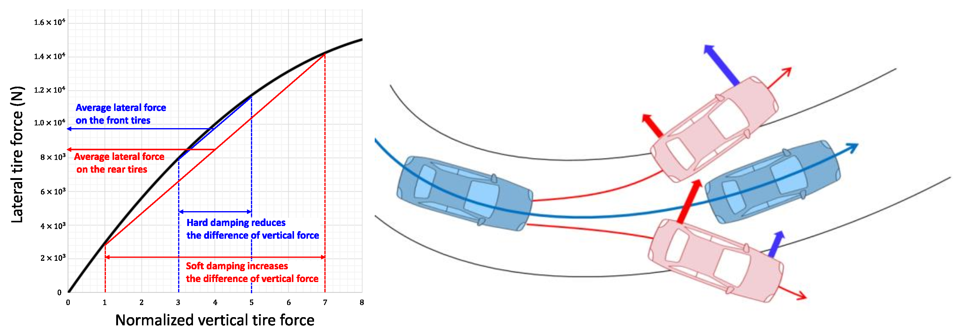
The mechanism for generating yaw assistance through the front and rear damping distribution is as follows. As shown in Figure 5, the lateral force of the tire is determined by the angle of slip, the friction coefficient, and the vertical force. In this context, the vertical force of each wheel can be changed by modifying the damping ratio. Depending on the left and right deviation of the tire’s vertical force, the lateral force of the left and right wheels changes nonlinearly, and the sum of the lateral forces becomes smaller. This allows the vehicle to assist in preventing understeer when the front wheel is applied a larger lateral force than the rear wheel and to improve oversteer when the rear wheel is applied a larger lateral force than the front wheel.
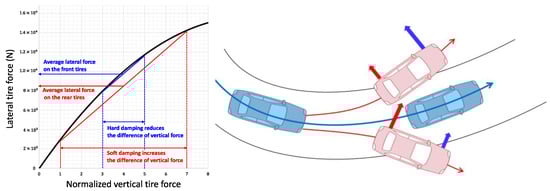
Figure 5.
Relationship between lateral tire force and vertical tire force.
In this study, the roll moment of the front and rear wheels is distributed according to the direction and magnitude of the understeer and oversteer. The effect of the roll moment is to restrain the roll change of the vehicle, which means that the sum of the left and right lateral forces increases by distributing the vertical force equally to the left and right wheels. The roll moment of the front and rear wheels is distributed as follows using the yaw rate error:
The quadratic problem with the same expression as (35) is given by
The solution is expressed in the same manner as Equations (36)–(40), as follows:
6.2.2. Control Utilization by Roll Region Index
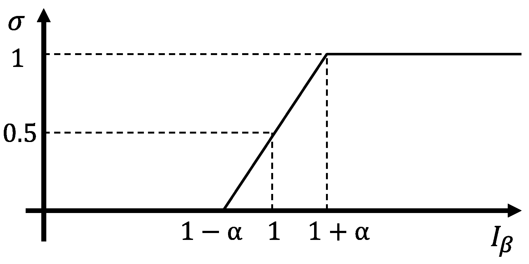
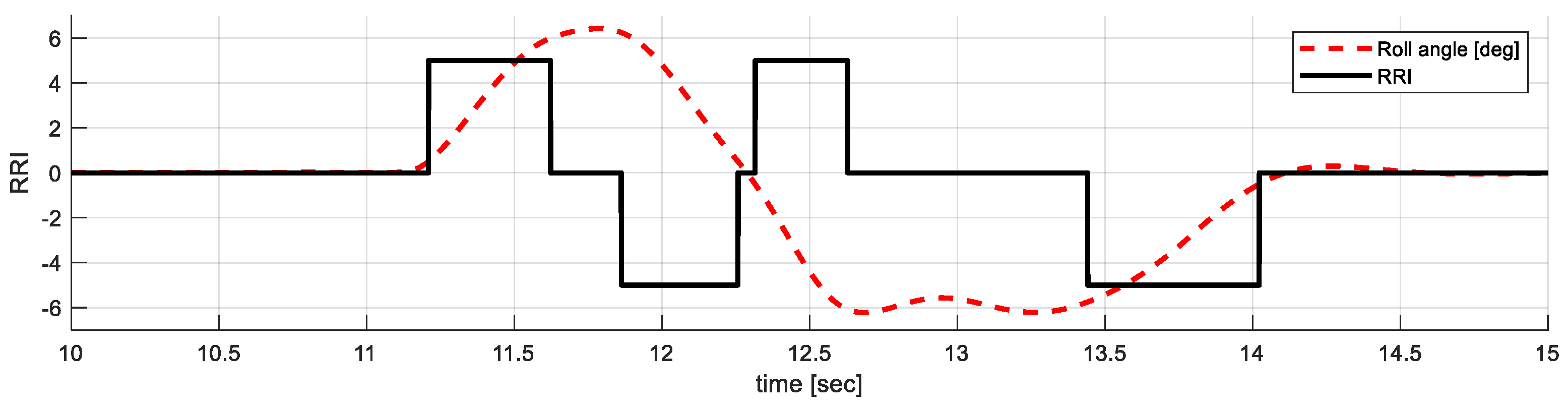
The above method that yaw assists control by the front/rear suspension damping distribution improves lateral stability, but the method has two problems. The first problem is a decrease in roll performance. When the conventional semi-active suspension control detects a turn of the vehicle, it keeps the full hard damping to minimize the roll angle. In contrast, if the front or rear wheels are softened for yaw assist control, the total roll damping coefficient of the vehicle is decreased, which causes a large roll angle in the driving. Thus, the previous yaw assist method improves lateral stability but loses roll performance. The second problem is that the effect of lateral acceleration due to changes in roll damping is neglected. As shown in the roll dynamics in Equation (31), the change in roll damping has a direct effect on the lateral acceleration. In addition, since the suspension is actually mounted along the kingpin angle, it further affects the lateral behavior more than the simplified roll dynamics model. Therefore, if the direction of change in the lateral acceleration due to roll damping is in a way that decreases lateral stability and minimizes roll behavior, and vice versa, increasing the roll behavior is advantageous for lateral stability. In this study, a suspension control method using the roll region index (RRI) is proposed to solve the above two problems. The roll region index is defined as follows:
where is the roll angle, is the roll rate, and is the roll rate threshold for transition. As shown in Figure 6, the RRI is used to determine whether the roll is increasing, decreasing, or in a transition state. Using this index, when the roll angle increases, the damping coefficient is increased to minimize the roll angle. On the other hand, when the vehicle’s roll angle returns to the origin, the damping is reduced to enhance the roll change.
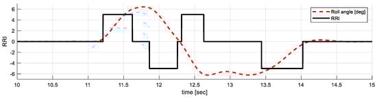
Figure 6.
Roll region index.
In view of the lateral motion of the sprung mass of the vehicle, during the increased roll period, the vehicle is forced to the side by inertia, so a large damping force must be applied in the opposite direction of the roll to improve the lateral behavior of the vehicle. On the other hand, if the direction of decreasing roll angle is in the same direction as the vehicle’s behavior or the driver’s steering direction, reducing the damping force leads to a faster change in the lateral behavior of the sprung mass. Thus, the RRI method not only reduces the maximum value of the roll angle but also increases the response of the roll control and, through it, improves the lateral behavior, such as yaw rate response, lateral acceleration response, and maximum side slip angle.
7. Result
The proposed algorithm is evaluated in simulation and on a real-world test. Because the suspension stroke variation must be considerable enough to allow the damping system to influence the vehicle’s lateral movement, a severe lane change maneuver is selected as the evaluation case. In general, these conditions require both lateral and roll stability, so the differential brake and damping control operate simultaneously to stabilize the vehicle. Three methods are evaluated to compare vehicle control performance. The first method is independent chassis control, with brake control for lateral stability and damping control (full hard, FH) for attitude stability. In other words, each chassis system is an independent control method that controls one of the yaw or roll directions. The second method is yaw assist control by damping (YAC), which assists lateral behavior by distributing front and rear suspension damping. In short, two chassis controls are integrated to maximize performance in one direction. The YAC method supports yaw behavior by switching the damping ratio of the front and rear wheels when understeer and oversteer are repeated during a sharp lane change. The third method, the proposed method, performs attitude control and yaw assist control according to the roll region index (RRI). When the RRI is 1, FH control is performed; otherwise, YAC control is executed, that is, the two chassis systems optimize the two directions according to the conditions.
7.1. Simulation
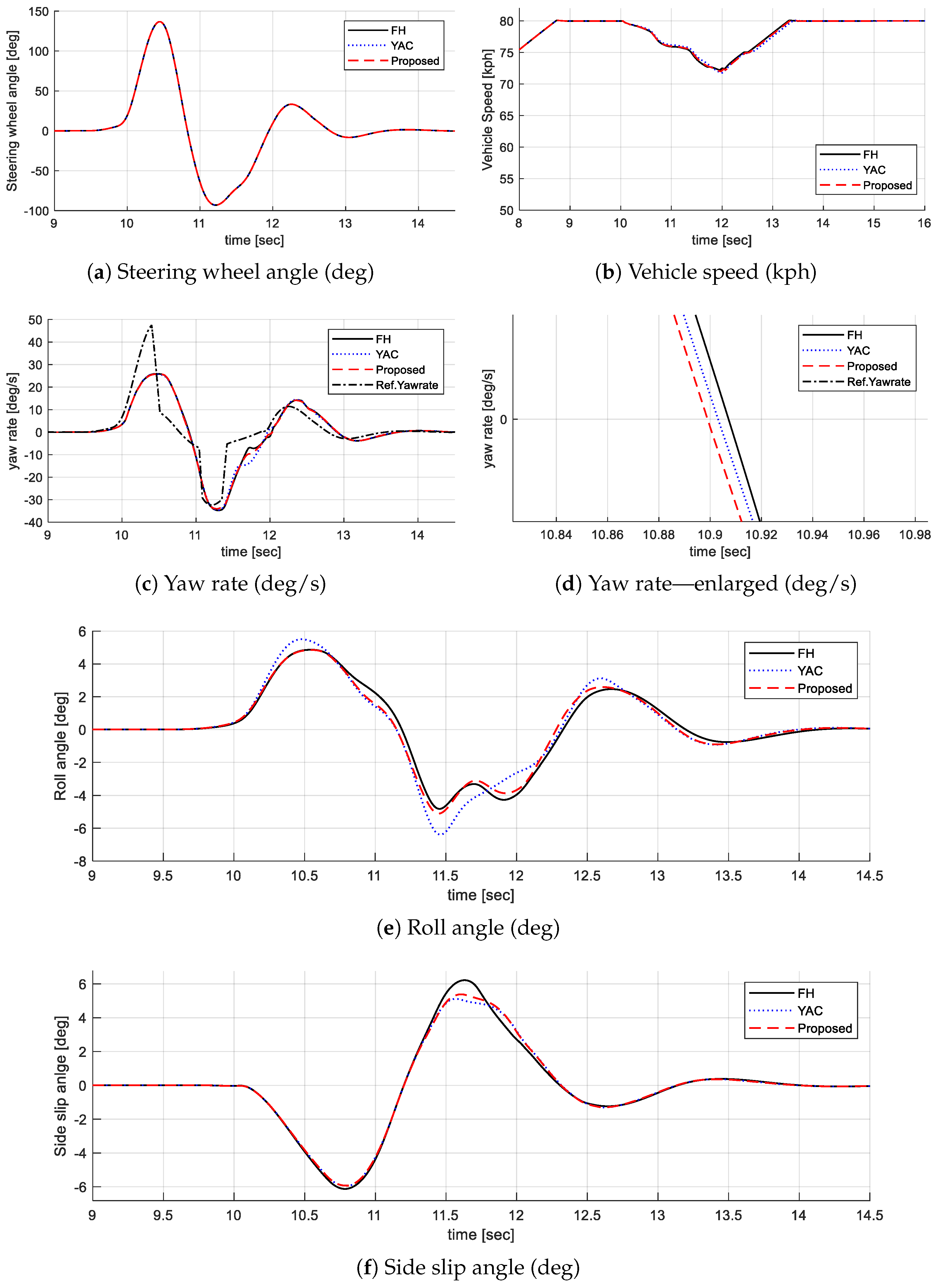
The simulation is executed in the Carsim/MATLAB environment, and vehicle parameters are set based on Hyundai Motors’ Electrified G80, which has specifications identical to those of the real-world test environment. The simulation assumes dry asphalt and uses a coefficient of friction of 0.9 for the road surface. The performance of each method was compared under the 80 km/h condition by applying the same steering angle as shown in Figure 7a,b. The test results are shown in Table 1 and Figure 7. The effect of the proposed method can be described in two aspects. The first is improvement in lateral performance. The YAC method makes a difference in lateral behavior by generating a difference in front and rear lateral force through damping distribution. As a result, as shown in Figure 7f, the proposed method and the YAC method reduce the side slip angle by 14.4% and 20.2% compared to the full hard method, respectively, improving the lateral stability of the vehicle. Furthermore, as shown in Figure 7c,d, the maximum value of the yaw rate is not significantly different, but the yaw rate response is improved by about 10~20 ms. In this case, the driver feels that the vehicle more quickly follows the driver’s intention, resulting in improved maneuverability. The second is improvement in roll performance. As shown in Figure 7e, the proposed method prioritizes attitude control according to the RRI when the roll increases and keeps the damping hard, which prevents the increasing roll. As a result, the maximum roll angle of the proposed method is about 5.09 degrees, which is 20.2% better than 6.38 degrees when the YAC method is applied, and it is almost as good as the performance when fully hard, with a difference of 5.8%. In addition, when the roll angle decreases, the total damping is softened by the yaw assist control, which makes the roll movement respond more quickly to the driver’s intention. In other words, the period where the steering phase and roll phase are reversed is decreased, so the vehicle’s heading direction and vehicle roll direction are aligned, and the driving feel is improved.
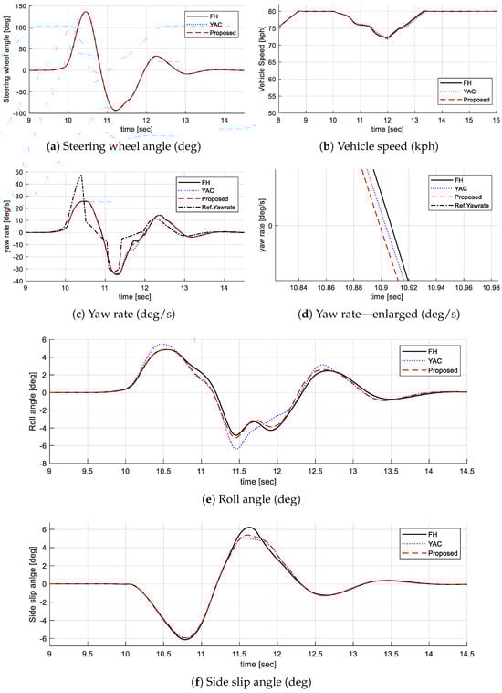
Figure 7.
Simulation result.

Table 1.
Simulation result.
7.2. Vehicle Test
7.2.1. Evaluation of Estimator
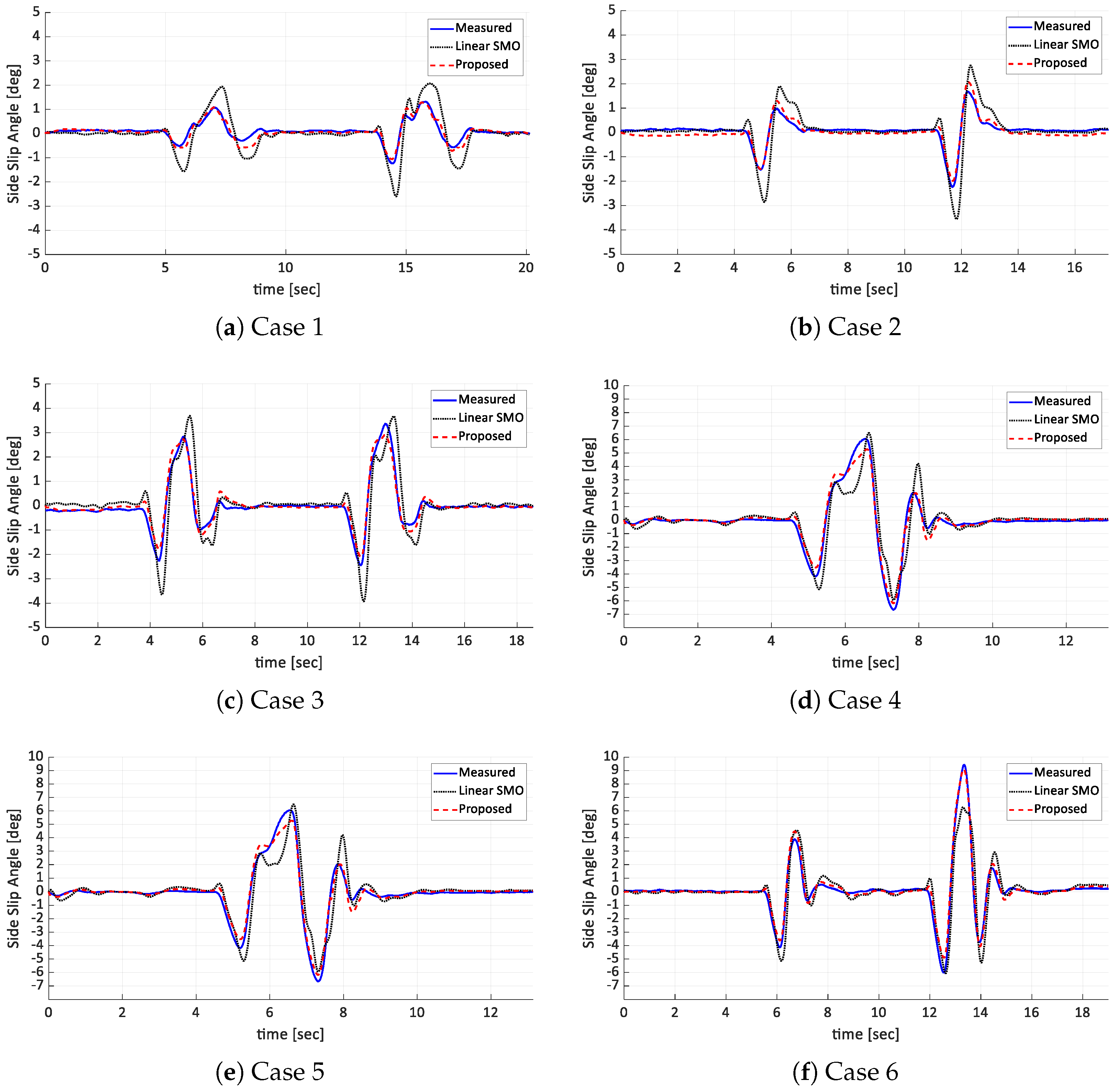
The test maneuver for estimator validation is selected as lane changes ranging from about 50 to 100 kph, with side slip angles measured from about 1 to 10 degrees. In practice, it is known that drivers feel nervous when the side slip angle is greater than about 3 degrees, and the range from 0 to 10 degrees includes almost all conditions that can occur in a driving situation. The performance of the estimator is verified by comparing it with the measured values of the RT3000. The sliding mode observer using the linear model is selected as a comparison group to check the performance of the combined model proposed in Section 3.3.
The evaluation result showed that, in most cases, the estimation error is within 1.0 degrees of the measured value with the RT3000, as shown in Table 2. Regarding the error with RT3000 measurements, the maximum error of the linear SMO was 2.9 degrees on average, while the proposed method improved the performance by about 72%, with a maximum error of 0.8 degrees on average. The average error of the total period is 0.42 degrees for the linear SMO and 0.18 degrees for the proposed method, which is an improvement of about 58%, showing the better performance of the proposed method. Figure 8 shows that the proposed method outperforms the linear SMO method in all cases. For linear SMO, the performance of the estimator was highly dependent on how the cornering stiffness constant is determined. As shown in Figure 8, the linear SMO has similar maximum values for conditions where the maximum side slip angle is around 5 to 6 degrees but tends to overestimate the true measurement in the 0 to 5 degrees range and underestimate the true measurement above 7 degrees. In other words, the linear SMO is ineffective for estimating a variety of conditions. However, the proposed method estimates the maximum side slip angle similarly under all conditions by using the side slip angle rate obtained from the kinematic model. In addition, the proposed method has a shorter time lag with the actual measurement than the conventional SMO, which significantly reduces the error at the same time.
Table 2.
Test result of estimator.
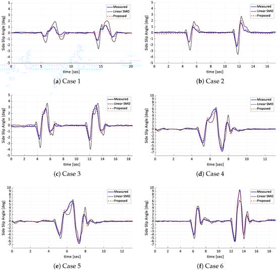
Figure 8.
Test result of estimator.
7.2.2. Validation of Integrated Chassis Control
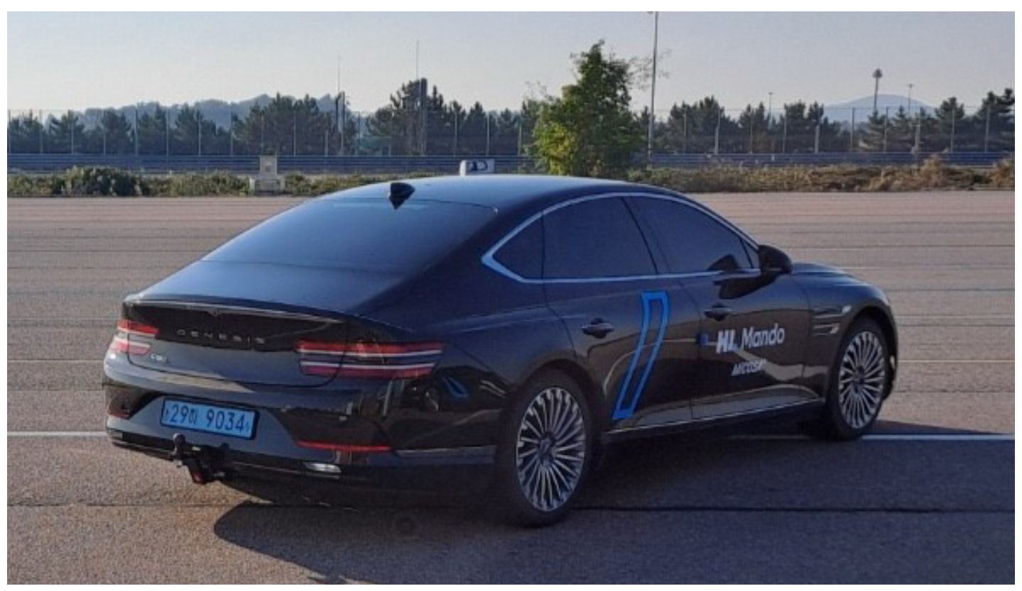
The test configuration is shown below. The test vehicle is an electrified G80 of Hyundai Motors, as shown in Figure 9. The vehicle has an electronic damping control suspension and brakes for chassis control. It is also equipped with an HL Mando steer-by-wire system. The road wheel actuator of the steer-by-wire system has a separate driver’s and tire’s steering wheel, allowing for independent tire wheel steering control. This allows us to pass the rack position corresponding to a predefined steering profile to the road wheel actuator, as shown in Figure 10a, and to use the trigger to start the steering profile at 80 km/h, as shown in Figure 10b, to achieve the same input. The integrated control logic was implemented using a rapid control prototype machine, the AUTOBOX II from dSPACE, Paderborn, Germany. Each actuator ECU was given control instructions via CAN communication. The driving environment was performed on dry asphalt under high-mu conditions. The tire specifications were 275/40/R19 for the front tires and 245/45/R19 for the rear tires. Each method was repeated five times to analyze reliable data, and the average value is shown.

Figure 9.
Test vehicle with steer-by-wire.
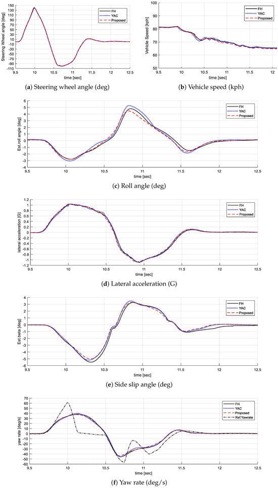
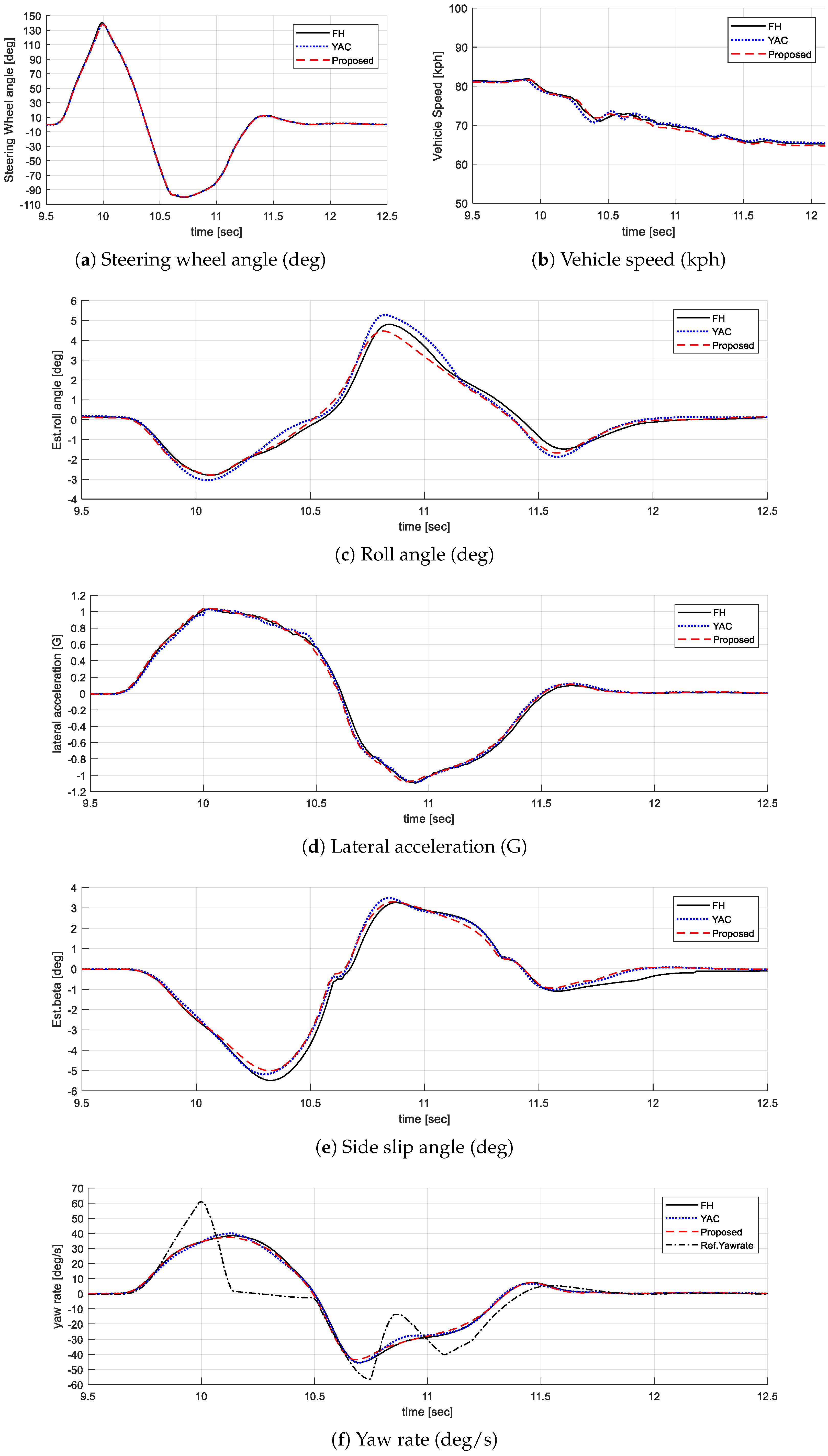
Figure 10.
Vehicle test result.
The validation results of real-world tests show improvements in roll and lateral performance, similar to the simulations. In terms of roll performance, as shown in Figure 10c, the maximum roll angle of the proposed method is 4.5 degrees, which is an improvement of approximately 7.3% and 17.4%, respectively, compared to the maximum roll angle of the FH method (4.8 degrees) and YAC method (5.4 degrees). In addition, the proposed method reduces the roll response by about 40–50 ms. The proposed method improves roll performance with a smaller maximum roll angle and a faster phase, similar to the result of simulations. This change in phase affects not only the roll but also the lateral behavior. As shown in Figure 10d, the lateral acceleration of the proposed method responds about 20 ms faster than the FH method, which also affects the side slip angle in Figure 10e, which is the integrated value. The results of the side slip angle show that the maximum value of the proposed method is 5.0 degrees, which is 8.7% and 3.6% better than the FH and YAC methods, respectively. In addition, the phase is reduced by about 30~40 ms. As shown in Figure 10f, the YAC method helps the yaw rate to rapidly track the reference yaw rate. Overall, only YAC control has the smallest error and, in some sections where the direction changes, such as 10.2 s and 10.7 s, the proposed method shows better performance.
This phenomenon is expected to result from the change in lateral behavior starting from a more stable state than vehicle attitude control. Consequently, by controlling attitude and yaw assist through classification of the roll region, both the maximum roll angle and maximum side slip angle are reduced. The response times of the roll angle, lateral acceleration, side slip angle, and yaw rate all improve, enhancing the vehicle’s response to the driver’s intentions.
8. Conclusions
This article presented an integrated chassis control of lateral and roll dynamics based on differential brake and suspension damping control using a hierarchical structure. The robust estimation algorithm of side slip angle is proposed in the estimation layer to determine the vehicle’s lateral stability. The supervision layer determines the control mode based on the vehicle’s state variables and generates control target values accordingly. Sliding mode control theory is applied to ensure robust control performance for nonlinearities in the vehicle model. The distribution layer distributes the yaw and roll moments to the brakes and suspension based on optimal distribution. Suspension control logic using the roll region index is proposed to satisfy roll and lateral performance simultaneously. The main contributions of this study are as follows.
- Previous hierarchical structure-based studies have performed suspension control under different conditions by switching the control mode, e.g., when roll stability is required, damping control is performed by reducing the roll angle. When lateral control is required, damping control assists the yaw moment by causing the front and rear wheel load transfer. However, since the limitation of the yaw assist method is that it only considers the relationship between the tire and the ground, this study proposes a method to maintain stiff damping when the movement of the sprung mass degrades the lateral stability.
- Two cases are selected for comparison with conventional suspension. The fully hard method does not improve lateral performance because it only considers attitude control by stiff damping, and the yaw assist control by damping method improves lateral performance but it has the disadvantage of decreasing roll performance. The proposed method can improve the overall performance of roll and lateral motion by controlling according to the roll region index. In a real-world evaluation, assuming a sharp lane change at 80 kph, the maximum roll angle was improved by about 17.4% compared to the yaw assist method, and the side slip angle was improved by about 8.7% compared to full hard damping.
- In a severe situation, it is important to have stability in both directions, not only lateral or roll stability. The proposed algorithm has the advantage of simultaneously improving both roll and lateral performance, making it more suitable for sudden situations.
Author Contributions
Conceptualization, K.L.; methodology, K.L.; software, J.S. and K.L.; validation, J.S. and K.L.; formal analysis, J.S. and K.L.; investigation, J.S. and K.L.; resources, J.S. and K.L.; data curation, J.S.; writing—original draft preparation, K.L.; writing—review and editing, K.L.; visualization, J.S. and K.L.; supervision, K.L.; project administration, K.L.; funding acquisition, K.L. All authors have read and agreed to the published version of the manuscript.
Funding
This research was conducted as part of an internal project supported by HL Mando, which provided the experimental environment. No external funding was received for this study.
Data Availability Statement
The datasets presented in this article are not readily available because the data are part of an ongoing study. Requests to access the datasets should be directed to the corresponding author.
Conflicts of Interest
Kyungtack Lee and Jinwoo Seol are employees of HL Mando. The paper reflects the views of the researchers and not the company.
References
- Mazzilli, V.; De Pinto, S.; Pascali, L.; Contrino, M.; Bottiglione, F.; Mantriota, G.; Gruber, P.; Sorniotti, A. Integrated chassis control: Classification, analysis and future trends. Annu. Rev. Control 2021, 51, 172–205. [Google Scholar] [CrossRef]
- Cho, W.; Choi, J.; Kim, C.; Choi, S.; Yi, K. Unified chassis control for the improvement of agility, maneuverability, and lateral stability. IEEE Trans. Veh. Technol. 2012, 61, 1008–1020. [Google Scholar] [CrossRef]
- Cheng, S.; Li, L.; Liu, C.Z.; Wu, X.; Fang, S.N.; Yong, J.W. Robust LMI-based H-infinite controller integrating AFS and DYC of autonomous vehicles with parametric uncertainties. IEEE Trans. Syst. Man, Cybern. Syst. 2020, 51, 6901–6910. [Google Scholar] [CrossRef]
- Xia, G.; Guo, D.; Tang, X.; Chen, W. Coordinated control of a semi-active suspension system and an electronic stability program on a finite-state basis. Int. J. Veh. Perform. 2019, 5, 187–212. [Google Scholar] [CrossRef]
- Zhao, J.; Wong, P.K.; Ma, X.; Xie, Z. Chassis integrated control for active suspension, active front steering and direct yaw moment systems using hierarchical strategy. Veh. Syst. Dyn. 2017, 55, 72–103. [Google Scholar] [CrossRef]
- Soltani, A.; Bagheri, A.; Azadi, S. Integrated vehicle dynamics control using semi-active suspension and active braking systems. Proc. Inst. Mech. Eng. Part K J. Multi-Body Dyn. 2018, 232, 314–329. [Google Scholar] [CrossRef]
- Chen, X.; Wang, M.; Wang, W. Unified chassis control of electric vehicles considering wheel vertical vibrations. Sensors 2021, 21, 3931. [Google Scholar] [CrossRef] [PubMed]
- Zhao, Z.; Zhang, L.; Ding, X.; Zhang, Z.; Li, S.; Gu, L. Integrated Active Suspension and Anti-Lock Braking Control for Four-Wheel-Independent-Drive Electric Vehicles. Chin. J. Mech. Eng. 2024, 37, 20. [Google Scholar] [CrossRef]
- Her, H.; Suh, J.; Yi, K. Integrated control of the differential braking, the suspension damping force and the active roll moment for improvement in the agility and the stability. Proc. Inst. Mech. Eng. Part D J. Automob. Eng. 2015, 229, 1145–1157. [Google Scholar] [CrossRef]
- Cheng, Y.; Hu, R.; Xu, W.; Yu, L. Integrated control strategy of semi-active suspension and in-wheel motors for handling limit of electric race car. Proc. Inst. Mech. Eng. Part D J. Automob. Eng. 2024, 238, 4486–4504. [Google Scholar] [CrossRef]
- Cho, W.; Suh, J.; You, S.H. Integrated motion control using a semi-active damper system to improve yaw-roll-pitch motion of a vehicle. IEEE Access 2021, 9, 52464–52473. [Google Scholar] [CrossRef]
- Yang, Y.; Liu, C.; Lai, S.K.; Chen, Z.; Chen, L. Frequency-dependent equivalent impedance analysis for optimizing vehicle inertial suspensions. Nonlinear Dyn. 2024, 1–26. [Google Scholar] [CrossRef]
- Chen, B.C.; Hsieh, F.C. Sideslip angle estimation using extended Kalman filter. Veh. Syst. Dyn. 2008, 46, 353–364. [Google Scholar] [CrossRef]
- Bevly, D.M.; Sheridan, R.; Gerdes, J.C. Integrating INS sensors with GPS velocity measurements for continuous estimation of vehicle sideslip and tire cornering stiffness. In Proceedings of the 2001 American Control Conference. (Cat. No. 01CH37148), Arlington, VA, USA, 25–27 June 2001; IEEE: New York, NY, USA, 2001; Volume 1, pp. 25–30. [Google Scholar]
- Baffet, G.; Charara, A.; Lechner, D. Estimation of vehicle sideslip, tire force and wheel cornering stiffness. Control Eng. Pract. 2009, 17, 1255–1264. [Google Scholar] [CrossRef]
- Joa, E.; Yi, K.; Hyun, Y. Estimation of the tire slip angle under various road conditions without tire–road information for vehicle stability control. Control Eng. Pract. 2019, 86, 129–143. [Google Scholar] [CrossRef]
- Chen, Y.; Ji, Y.; Guo, K. A Sliding Mode Observer for Vehicle Slip Angle and Tire Force Estimation; Technical report, SAE Technical Paper; SAE: Warrendale, PA, USA, 2014. [Google Scholar]
- Piyabongkarn, D.; Rajamani, R.; Grogg, J.A.; Lew, J.Y. Development and experimental evaluation of a slip angle estimator for vehicle stability control. IEEE Trans. Control Syst. Technol. 2008, 17, 78–88. [Google Scholar] [CrossRef]
Disclaimer/Publisher’s Note: The statements, opinions and data contained in all publications are solely those of the individual author(s) and contributor(s) and not of MDPI and/or the editor(s). MDPI and/or the editor(s) disclaim responsibility for any injury to people or property resulting from any ideas, methods, instructions or products referred to in the content. |
© 2025 by the authors. Published by MDPI on behalf of the World Electric Vehicle Association. Licensee MDPI, Basel, Switzerland. This article is an open access article distributed under the terms and conditions of the Creative Commons Attribution (CC BY) license (https://creativecommons.org/licenses/by/4.0/).