Abstract
This study proposes an in-wheel assembly with a variable speed-reduction device designed to maximize torque and vehicle speed, enabling high-performance vehicle-level driving characteristics in front-engine, rear-wheel drive (FR), internal combustion engine (ICE) vehicles, where conventional EV motors cannot facilitate e-4WD. The proposed system integrates a motor and speed reducer within the wheel while avoiding interference from braking, steering, and suspension components. Through various innovative approaches, concepts for an integrated wheel-bearing planetary reducer and a variable speed planetary reducer were derived. The developed system achieved twice the maximum torque and a 35% increase in top speed compared to previously developed in-wheel systems, all without altering the front hard points. Multi-body dynamic analysis and component testing revealed wheel lock-up issues during reverse driving, and instability in the one-way clutch at high speeds. To address these issues, the power transmission structure was improved, and the type of one-way clutch was modified. Additionally, deficiencies in lubrication supply to the friction surface of the one-way clutch were identified through flow analysis and visualization tests, leading to design improvements. The findings of this study demonstrate that even in in-wheel systems where the application of large and complex transmission devices is challenging, it is possible to simultaneously enhance both maximum torque and top vehicle speed to achieve high-performance vehicle-level driving dynamics. Consequently, implementing an in-wheel e-4WD system in ICE FR vehicles is expected to improve fuel efficiency, achieve high-performance vehicle capabilities, and enhance market competitiveness.
1. Introduction
Recently, automotive manufacturers have been making significant efforts to develop electrification technologies to gain a competitive edge in the electric vehicle (EV) market. Among these technologies, the in-wheel system is gaining attention as a promising future technology. The in-wheel system integrates a motor and a speed reducer within the wheel, in addition to the suspension, steering, and braking components, to drive the wheel directly. By eliminating the drive shaft, this system enables independent driving and regenerative braking at each wheel, thereby improving both driving performance and energy efficiency [1,2]. From a vehicle packaging perspective, the in-wheel system may be the only viable solution for implementing e-4WD in front-engine, rear-wheel drive (FR), internal combustion engine (ICE) vehicles and fuel cell electric vehicles (FCEVs) without interference from the engine or hydrogen tank.
Due to these advantages, various companies have been actively researching and developing in-wheel systems for many years [3]. Toyota has developed an in-wheel system with a power output of 55 kW and a maximum wheel torque of 1200 Nm, which can be integrated with a front-wheel caliper in a 17-inch wheel. The company is also developing various control logics for four-wheel in-wheel vehicles [4]. Schaeffler developed the E-Wheel Drive system by further integrating the drive motor, electrical equipment, and braking and cooling systems [5]. Protean proposed the concept of integrating the motor and brake and connecting the motor directly to drive the wheels [6].
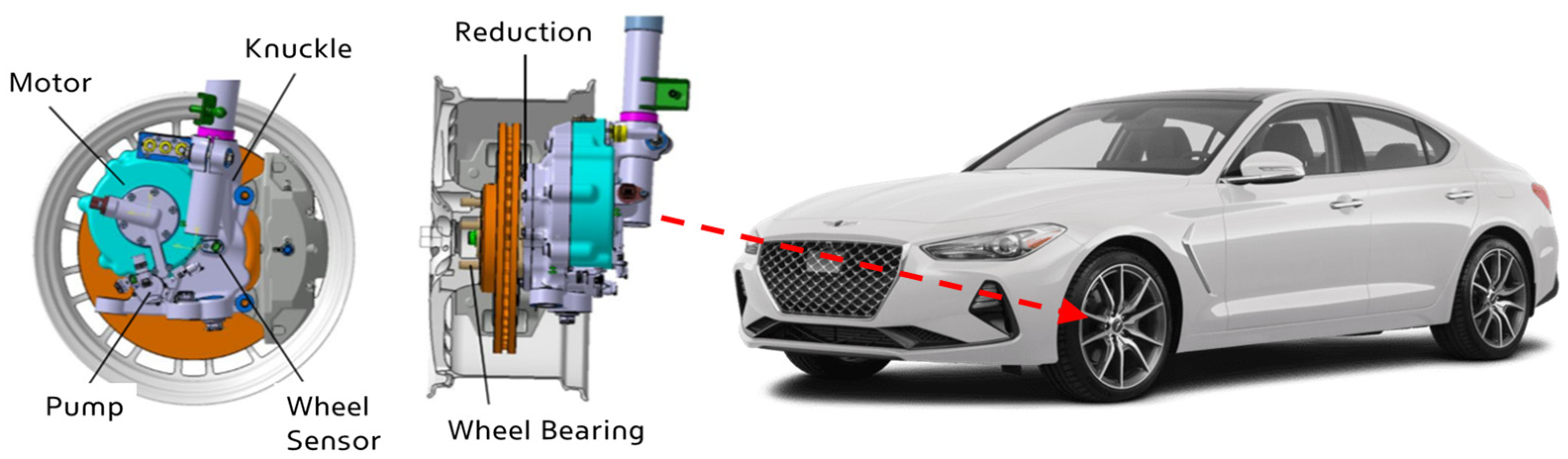
As presented in Table 1, Hyundai Mobis has been developing in-wheel systems since 2010, validating in-wheel e-4WD performance across various vehicle models. In 2013, an in-wheel system was installed in the rear wheels of the Ray EV, enhancing cornering stability and low-friction split escape performance, thereby achieving 6+ to 7− 4WD performance. In 2015, the system’s e-4WD performance was tested at a winter proving ground in China [7]. In 2016, the in-wheel system was applied to the front wheels of the Genesis G80, demonstrating improved yaw stability in one-circle turns, step steer, sine sweep, and double lane change tests, as well as enhanced climbing performance on low-friction surfaces compared to mechanical 4WD systems [8,9]. In 2017, an in-wheel system was developed for the rear wheels of the NEXO, achieving 6 to 6+ 4WD performance, which was 1.5 levels superior to 2WD, and enabling an 8% gradient ascent on snowy roads. The in-wheel system developed in 2019 featured a motor output of 30 kW, a maximum torque of 650 Nm, and a top speed of 200 km/h. It was installed on the front wheels of the high-performance G70 without modifying the hard points. As presented in Figure 1, in 2021, Hyundai Motor Company’s high-performance vehicle development team verified that in-wheel torque vectoring control could enhance the agility and responsiveness of high-performance vehicles [10].

Table 1.
Developed in-wheel e-4WD specifications.

Figure 1.
In-wheel e-4WD configuration of G70.
Previous in-wheel e-4WD systems have faced challenges in achieving sufficient 4WD performance due to motor size limitations within the confined wheel space. To achieve maximum torque equivalent to mechanical 4WD without increasing motor size, a higher reduction ratio is required. However, in in-wheel gearboxes composed of planetary gears and external gears, the external gear reduction ratio is constrained by the center distance between the wheel shaft and the motor shaft, while the planetary gear reduction ratio is limited by the diameter of the ring gear, which is located inside the motor end coil. These constraints make it difficult to increase the overall reduction ratio.
In this study, a novel variable speed-reduction device is proposed to enhance both torque and vehicle speed simultaneously within the limited space of the wheel, without increasing motor size. The study further explores the entire process of design, analysis, and testing to assess the characteristics of the variable speed-reduction device and address any identified issues.
2. Structure and Characteristics
2.1. Hub Bearing Integrated Planetary Gear Set
The in-wheel motor and reduction ratio applied to the front wheels of the G70 were insufficient to meet the high-speed cornering performance requirements targeted by Hyundai Motor Company (HMC) for high-performance vehicles, necessitating more than a twofold increase in wheel torque. However, as shown in the rear view of the in-wheel motor within the wheel in Figure 1, increasing the motor size within the limited wheel space would interfere with the steering and braking systems. Therefore, instead of increasing the motor size, torque was enhanced by incorporating a reduction gear into the existing motor. However, adding a reduction gear increases the overall width of the assembly, causing the motor to protrude further inward toward the vehicle. As shown in the side view of the in-wheel system in Figure 1, this results in interference with the damper strut. To accommodate a reduction gear within these stringent packaging constraints, a hub bearing integrated planetary gear set (HB-PGS) was developed. The concept and block diagram of this HB-PGS are illustrated in Figure 2a,b.

Figure 2.
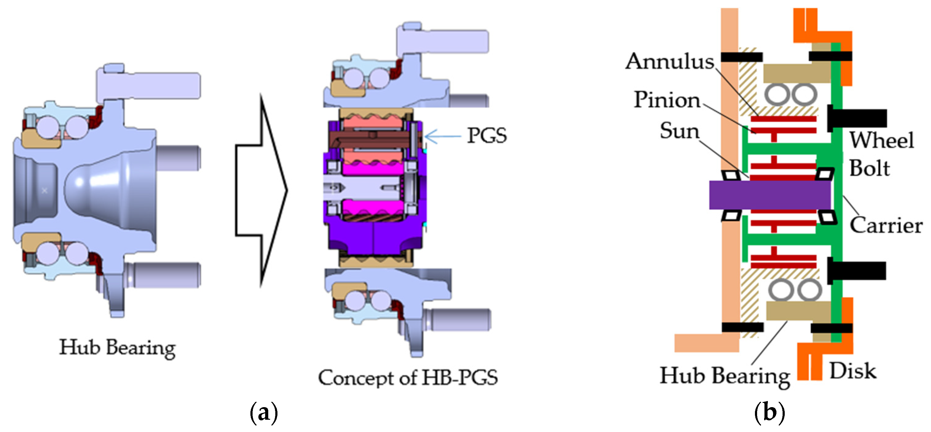
(a) Concept of hub bearing integrated PGS. (b) Block diagram of HB-PGS.
As shown in Figure 2a, the proposed concept involves integrating a planetary gear set—comprising a sun gear, planetary gears, a carrier, and a ring gear—within the hub bearing. To fit the PGS within the hub bearing, the ball pitch circle diameter (PCD) of the hub bearing was maximized within the available space inside the front disk hat. Additionally, instead of attaching the wheel bolts directly to the hub bearing, they were press-fitted into the PGS carrier. By maintaining the wheel bolt PCD identical to that of conventional systems, existing wheels could be used without modification. The carrier was bolted to the hub bearing, enabling the hub bearing to support both the wheel load and the output load from the carrier. This configuration effectively distributes the structural functions between the hub bearing and the carrier, with the hub bearing primarily supporting the wheel load while also assisting in output transmission.
Unlike conventional, third-generation hub bearings, in which the inner race rotates and the outer race is fixed, the proposed design features a fixed inner race and a rotating outer race. The ring gear was fixed to the hub bearing’s inner race, allowing the input power from the sun gear to be transmitted through the carrier to the wheel, thereby achieving the maximum reduction ratio. Additionally, to prevent the leakage of lubricating oil for the gears and bearings from the hub bearing integrated PGS, seals were carefully designed. The structural rigidity of the hub bearing, PGS assembly process, concentricity maintenance, and oil flow characteristics were all considered in the design process to ensure optimal performance.
2.2. Variable One-Way Clutch with PGS
When the HB-PGS is applied to the G70 in-wheel system to increase the reduction ratio, the maximum vehicle speed decreases due to motor speed limitations. Doubling the reduction ratio would result in a twofold increase in wheel torque, but it would also reduce the maximum vehicle speed by half. Therefore, to incorporate a reduction gear while still achieving the top high speed required for high-performance vehicles, a gear-shifting mechanism is necessary. However, conventional multi-speed transmission systems, such as hydraulic or shift fork-based transmissions, have complex structures and require additional actuators, making them unsuitable for integration within the constrained space of an in-wheel system.
Since the G70 in-wheel system is used as an auxiliary drive system rather than a primary propulsion system, unlike the main engine, it is not required to deliver driving performance under all conditions. Therefore, a new, efficient, and compact clutch solution was needed—one that would provide maximum torque to assist during vehicle launch and hill climbing while enabling freewheeling rotation at high speeds to prevent exceeding the motor’s maximum speed. To address this challenge, a variable speed-reduction device was devised by combining two OWCs with the PGS. This mechanism ensures a high reduction ratio during driving and a low reduction ratio during freewheeling or regenerative braking.
The variable one-way clutch (VOWC), which enables the transition between reduction ratios, consists of two OWCs arranged in opposite orientations on the rotor, with one OWC connecting the rotor to the sun gear and the other connecting the rotor to the carrier in a symmetrical configuration. The rotor extends through the sun gear to the carrier, with both OWCs linking the rotor to the respective components. During torque transmission, only one of the two OWCs locks, while the other remains in a freewheel state, thereby altering the reduction ratio. The block diagram illustrating the entire power transmission system, including the VOWC, PGS, and external gears, as well as the target T-N (torque–speed) curve for the real vehicle when this system is applied, is shown in Figure 3a,b.
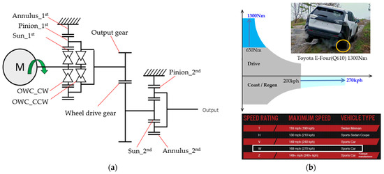
Figure 3.
(a) The block diagram of power transmission. (b) The target T-N (torque–speed) curve.
2.3. Gear Shifting Process of VOWC and PGS
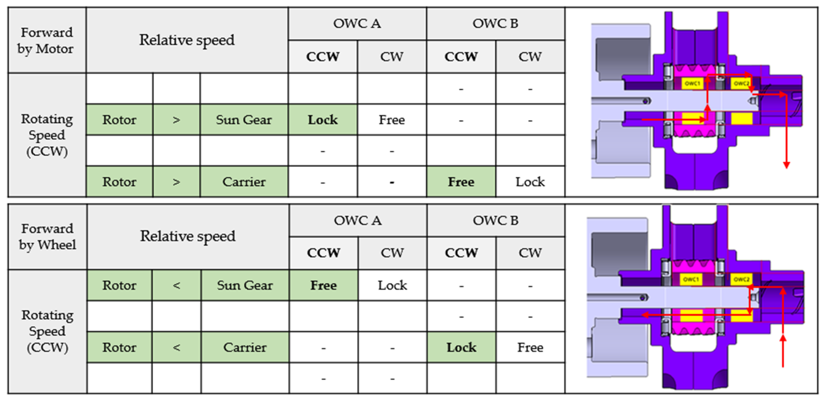
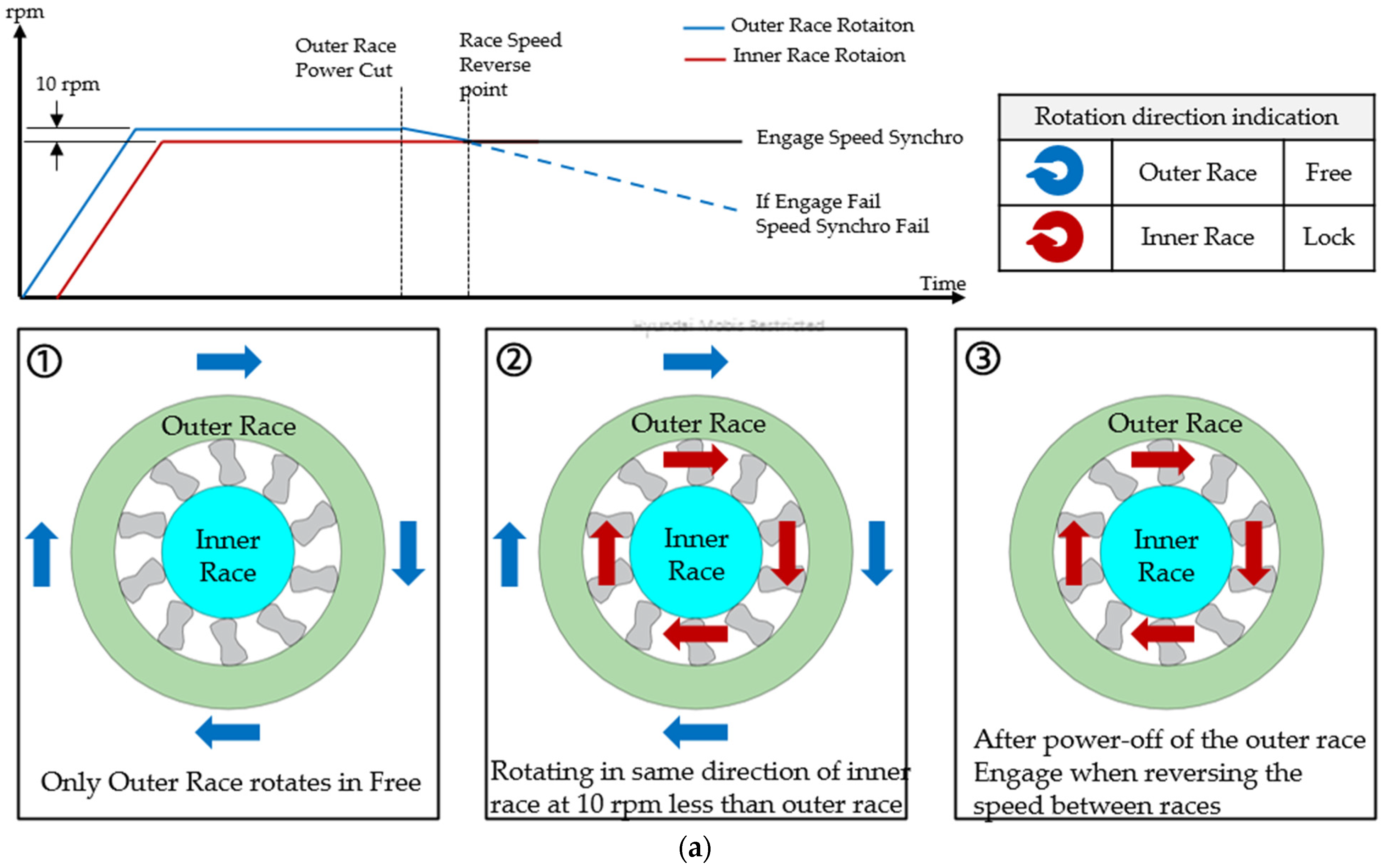
The gear ratio shifting process through the combination of the PGS and VOWC can be explained as follows. When torque is generated by the motor, the transmission sequence is as follows: rotor → sun gear OWC lock (rotor rotational speed > sun gear rotational speed) → sun gear → planetary gears (reduction) → carrier. As a result, the torque is amplified according to the reduction ratio. Conversely, when torque is generated at the wheel, the transmission sequence is as follows: carrier → carrier OWC lock (rotor rotational speed < carrier rotational speed) → rotor. In this case, the torque is directly transmitted to the rotor. Figure 4 illustrates the operational state of each OWC based on the location of torque generation and the relative rotational speeds of the components.
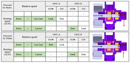
Figure 4.
The operational state of each OWC based on the location of torque generation and the relative rotational speeds of the components in forward.
The gear ratio shifting process during driving consists of two phases: the torque transmission phase and the speed synchronization phase.
- Torque Transmission Phase: In this phase, the rotor shaft engages with one of the two OWCs to transmit torque. This phase ends once the required torque is achieved.
- Speed Synchronization Phase: In this phase, the rotor shaft is not engaged with either OWC, and its speed transitions between the rotational speeds of the sun gear and the carrier. This phase ends once the speed difference between the rotor and either component is eliminated.
The transition between the torque transmission phase and the speed synchronization phase is controlled entirely through motor speed and torque control, eliminating the need for an additional actuator. The rotor speed varies only within the range between the carrier speed (minimum) and the sun gear speed (maximum), and since it is proportional to the reduction ratio of the PGS, the speed difference increases at higher speeds. Therefore, precise rotor speed control is required in the low-speed range to ensure smooth synchronization.
When transitioning from 2WD to 4WD to provide auxiliary driving force, the rotor is initially connected to the carrier OWC and synchronized with the carrier speed in the 2WD driving state. To shift to 4WD, the rotor speed is first increased until it matches the rotational speed of the sun gear. Once synchronization with the sun gear is achieved, the motor torque is increased to lock the sun gear OWC, completing the transition to the 4WD mode. Conversely, when transitioning from 4WD to 2WD at high vehicle speeds, the rotor—initially connected to the sun gear OWC—has its rotational speed reduced to a level between the speeds of the carrier and the sun gear. This ensures that at high speeds, the motor does not act as a resistance force. During regenerative braking in either the 2WD or 4WD mode, the rotor speed is first synchronized with the carrier speed, after which reverse torque is generated to lock the carrier OWC, enabling effective energy recovery.
2.4. Resolving the Interlock Issue in the PGS and VOWC Combination
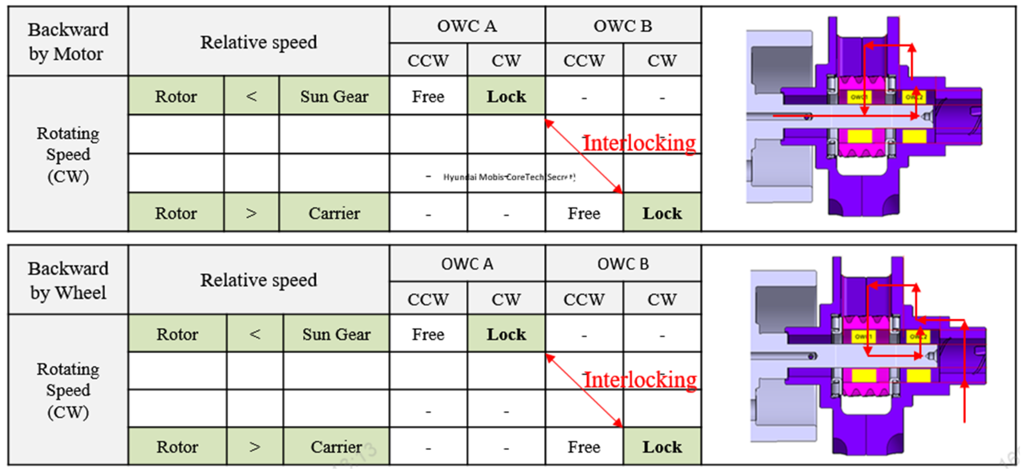
A key issue with the combination of the PGS and the VOWC arises during clockwise (CW) rotation, where both OWCs lock simultaneously regardless of the torque generation point. As illustrated in Figure 5, when torque is generated at the rotor in the CW direction, the rotor’s rotational speed exceeds that of the carrier, causing the carrier OWC to lock first. As the carrier rotates, it accelerates the sun gear, eventually making the sun gear rotate faster than the rotor, thereby locking the sun gear OWC as well. This results in an interlock of both OWCs. Similarly, when torque is generated at the wheel in the CW direction, the carrier rotation accelerates the sun gear, causing the sun gear OWC to lock as the sun gear’s rotational speed exceeds that of the rotor. As the rotor then synchronizes with the sun gear’s speed, it eventually surpasses the carrier’s speed, causing the carrier OWC to lock, again leading to an interlock of both OWCs.
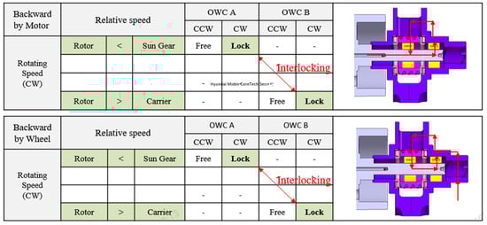
Figure 5.
The operational state of each OWC based on the location of torque generation and the relative rotational speeds of the components in backward.
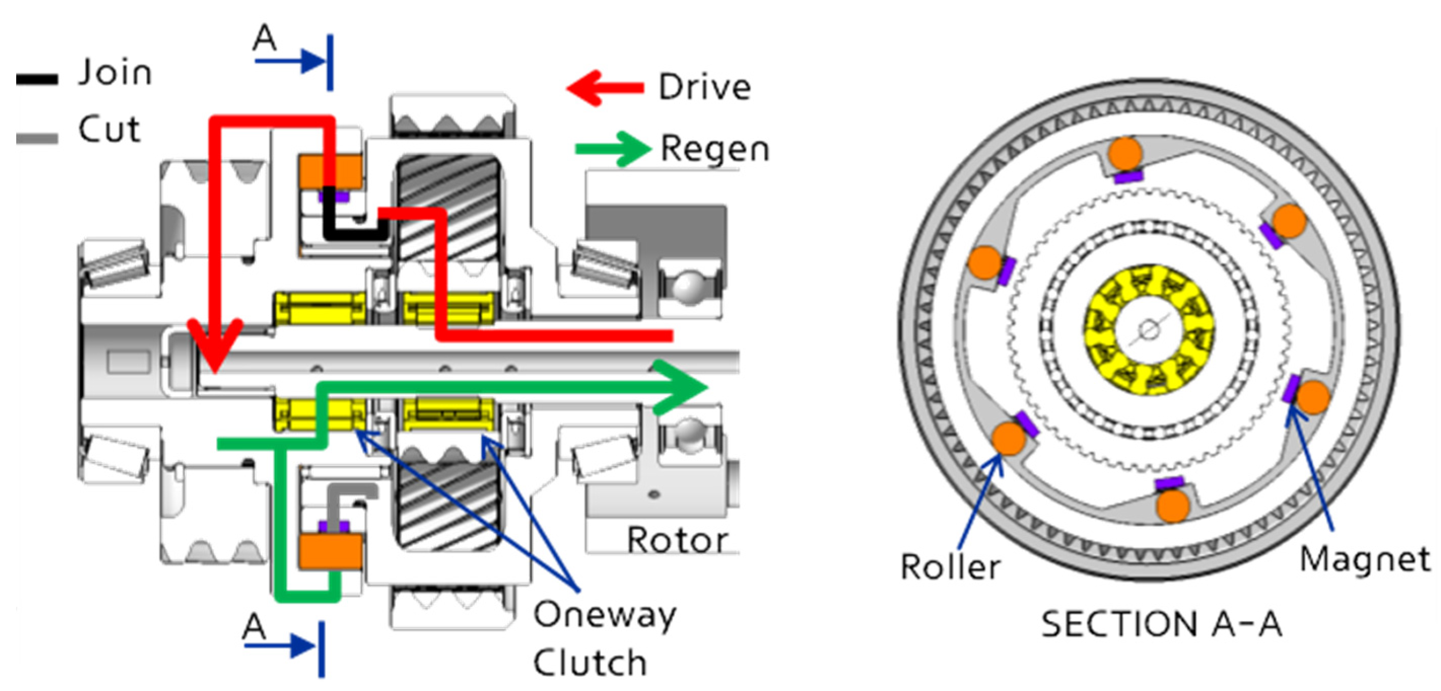
To resolve the OWC interlock issue during reverse rotation, the output gear was decoupled from the carrier and instead connected to a separate shaft. The OWC, which was previously linked to the carrier, was relocated to the new output gear shaft. Additionally, power transmission between the carrier and the output gear shaft was modified using a roller, magnet, and wedge mechanism.
- When torque is generated by the motor, the carrier rotates, inducing a centrifugal force on the roller. When the centrifugal force exceeds the magnetic force, the roller detaches from the magnet and becomes engaged in the wedge structure, thereby transmitting driving force.
- When torque is generated at the wheel, the output gear shaft rotates, but since the roller is not subject to centrifugal force, it remains fixed by the magnet and does not engage with the wedge structure. As a result, the PGS does not rotate, and the rotor, which is connected to the OWC and the output gear shaft, rotates together.
This design modification effectively prevents the OWC interlock issue, ensuring stable power transmission and improved system reliability. The structure of the new design is shown in Figure 6.
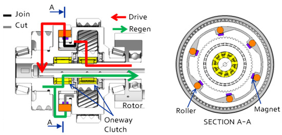
Figure 6.
The structure of the new design of preventing OWC interlock.
2.5. Overall Structure and Characteristics
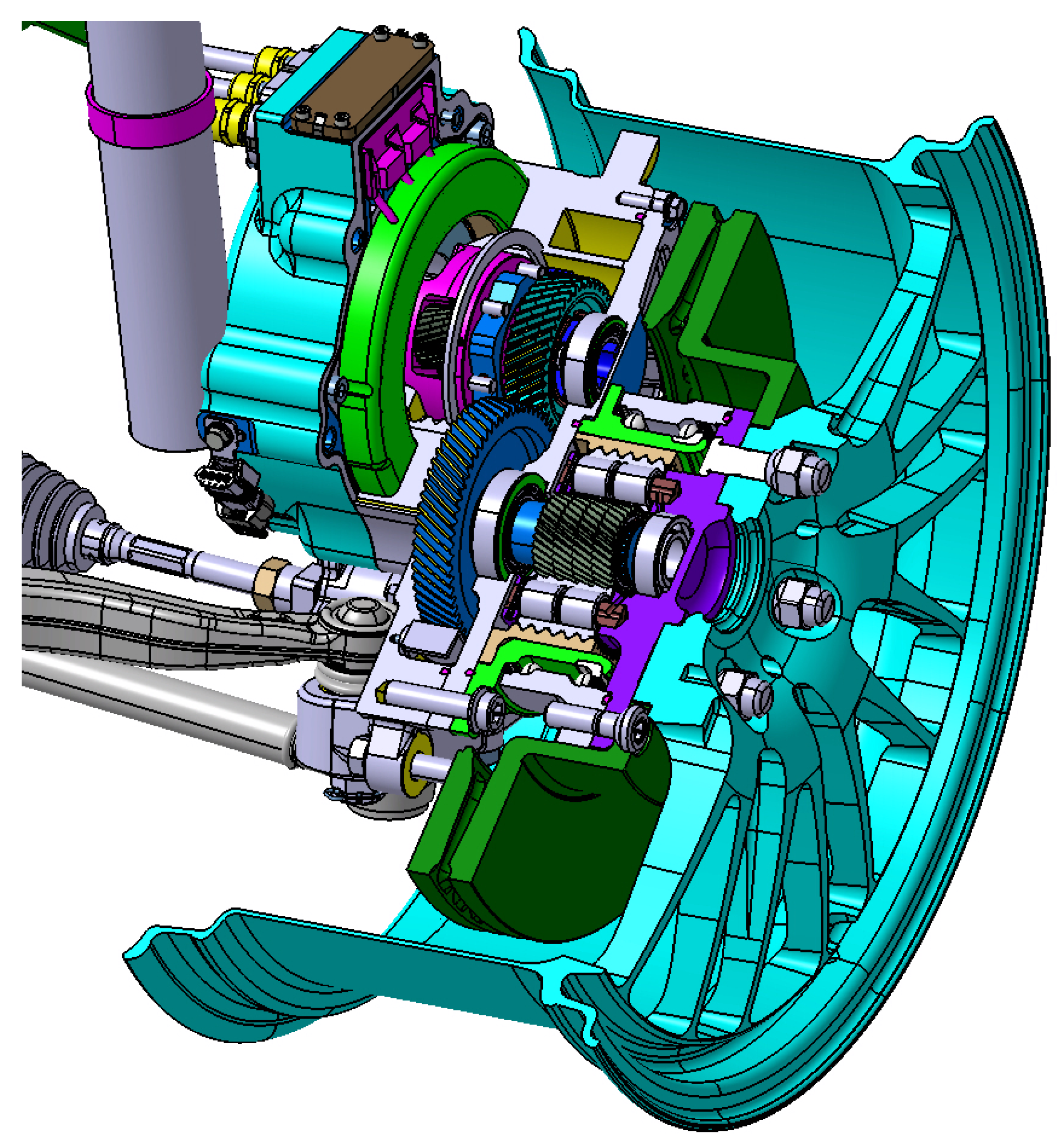
By integrating the hub bearing planetary gear set (HB-PGS) and the variable one-way clutch planetary gear set (VOWC-PGS) into the existing in-wheel system, it was possible to achieve both the maximum torque and top speed required for high-performance vehicles without modifying the suspension, steering, or braking systems. The one-way clutch (OWC) was designed by analyzing Hertzian stress at the sprag contact points, hoop stress in the inner (rotor shaft) and outer (sun gear) components, rollover torque, and service life to ensure optimal performance. The two PGS units were designed to provide maximum reduction ratios while ensuring sufficient gear strength and bearing durability. Additionally, the external gear reduction ratio was adjusted to set the overall reduction ratio at 1:18.7, as shown in Figure 7. As presented in Table 2, the proposed system achieves higher torque and greater vehicle speed compared to Toyota’s in-wheel system, highlighting its superior performance.

Figure 7.
Overall structure of in-wheel assembly with the HB-PGS and VOWC-PGS.
Table 2.
Comparison of the main technical parameters.
3. Simulation Model and Test Results
To verify whether the engagement between the inner and outer races of the one-way clutch (OWC) remains stable under centrifugal force and to analyze variations in the meshing load between the sun gear and planetary gears, a dynamic analysis model of the OWC and planetary gear set (PGS) was developed. The OWC model includes the inner race, outer race, sprag, and ribbon spring, while the PGS model consists of the sun gear, planetary gears, carrier, and ring gear. All components were modeled as flexible bodies to capture realistic deformation and interaction effects. The initial ribbon spring force in the OWC was determined based on X-ray imaging of the OWC structure and the drag torque in the freewheel state. The ribbon spring stiffness and preload were adjusted accordingly. A simulation of the sprag and inner race separation speed under centrifugal force was conducted, and the results are illustrated in Figure 8a. As shown, when the OWC rotates, the inner and outer races initially rotate together. However, at rotational speeds above 5000 rpm, the contact force between the sprag and inner race reaches zero, causing a relative speed difference between the components. After this point, even when a 1 Nm locking torque is applied to the inner race, it fails to engage and continues freewheeling.
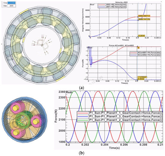
Figure 8.
(a) Dynamic analysis of the OWC. (b) Dynamic analysis of the PGS.
Additionally, a PGS analysis model was developed to investigate the meshing behavior of planetary gears. When a 100 Nm input torque was applied to the sun gear, the mesh phasing effect among the planetary gears caused the gear contact forces to be sequentially distributed, as illustrated in Figure 8b.
3.1. Dynamic Behavior Analysis of VOWC in Low Speed
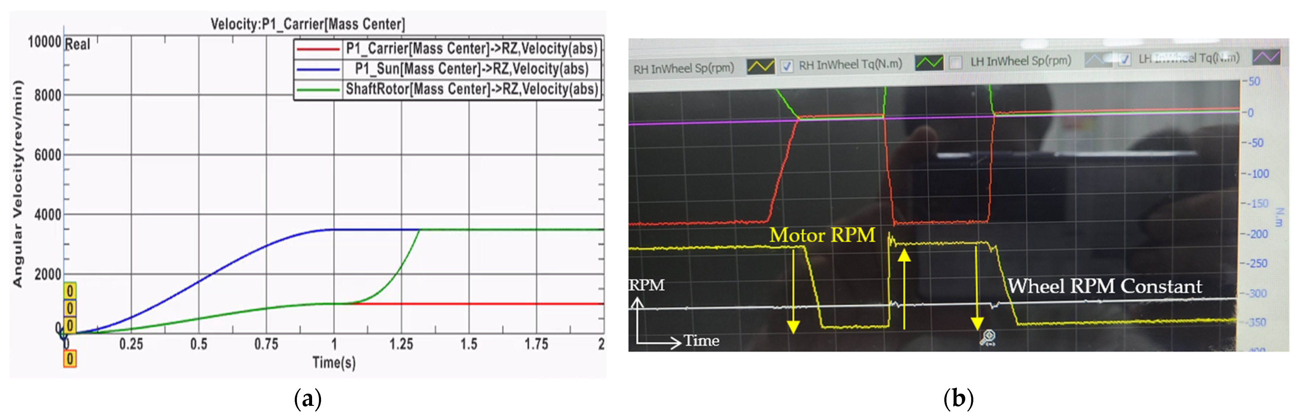
To analyze the dynamic behavior of gear meshing and the one-way clutch (OWC) under conditions where the reduction ratio increases (18.72:1) when auxiliary drive engagement is required during freewheeling, a simulation study was conducted. As shown in Figure 9a, in the initial freewheeling state, the planetary carrier (red) and rotor shaft (green) rotate together at a low speed (1000 rpm), while the sun gear (blue) rotates at a relatively high speed (3484 rpm) in a freewheel state. When a 6 Nm torque is applied to the motor, the rotor speed increases until it surpasses the sun gear speed (3484 rpm), at which point the rotor and sun gear engage, transmitting driving force to the sun gear. During this process, the carrier speed remains constant at 1000 rpm, while only the rotor speed increases (from 1000 rpm to 3484 rpm).

Figure 9.
(a) Dynamic analysis of the VOWC in low speed. (b) Test results of the VOWC.
Furthermore, the test results shown in Figure 9b confirmed the same behavior. When motor torque was applied and removed, the wheel rotation speed remained constant, while only the motor speed either increased or decreased, demonstrating the effectiveness of the proposed system in controlling gear engagement and speed variation.
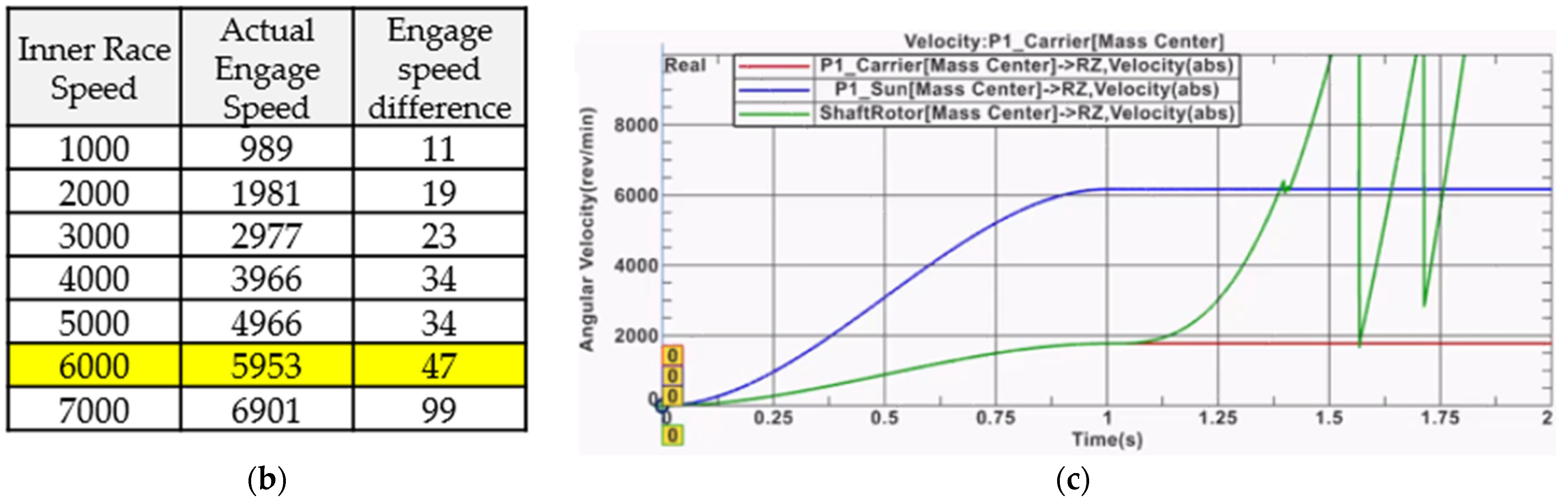
3.2. Dynamic Behavior Analysis of VOWC in High Speed
An experimental study was conducted to determine the difference in the engagement speed limit between the outer race and inner race of the one-way clutch (OWC) as rotational speed increased. As shown in Figure 10a, up to 6000 rpm, the engagement time increased proportionally with the speed difference between the inner race and outer race, while engagement remained stable. However, as shown in Figure 10b, beyond 6000 rpm, centrifugal forces destabilized the engagement, leading to further increases in engagement time. At higher rotor speeds, the speed difference at the point of engagement increases, causing higher impact forces when the rotor engages with the sun gear. This impact may lead to OWC rollover, as confirmed through computational analysis, as illustrated in Figure 10c.
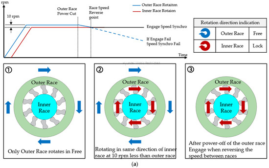
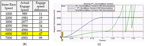
Figure 10.
(a) Test of VOWC engagement limits at high rotational speeds. (b) Test results of the engagement limits. (c) Dynamic analysis of the VOWC at high speed.
4. Improvement of the VOWC
4.1. Disengage-Type OWC
Based on the multi-body dynamic analysis and experimental results, the sprag design of the OWC was modified from a disengage type to an engage type to improve its stability at high rotational speeds. In general, the engage-type OWC reduces friction losses during freewheeling by allowing centrifugal forces to disengage the sprag from the inner race. However, it is not suitable for applications requiring stable engagement at high speeds. Conversely, the disengage-type OWC maintains stable engagement at high speeds because centrifugal forces press the sprag against the inner race. However, since the sprag and race remain in continuous contact, proper lubrication of the contact surfaces is critical to ensure durability and performance. A dynamometer test was conducted using the engage-type OWC, in which the output-side speed was increased in increments of 100 rpm, and the input torque was increased in increments of 10 Nm. During testing, OWC rollover occurred, and a post-test disassembly inspection revealed that thermal stress had developed at the contact interface between the rotor shaft and the OWC due to insufficient lubrication, as shown in Figure 11.
Figure 11.
Thermal stress in rotor shaft and OWC Rollover.
4.2. Simulation and Visualization of Oil
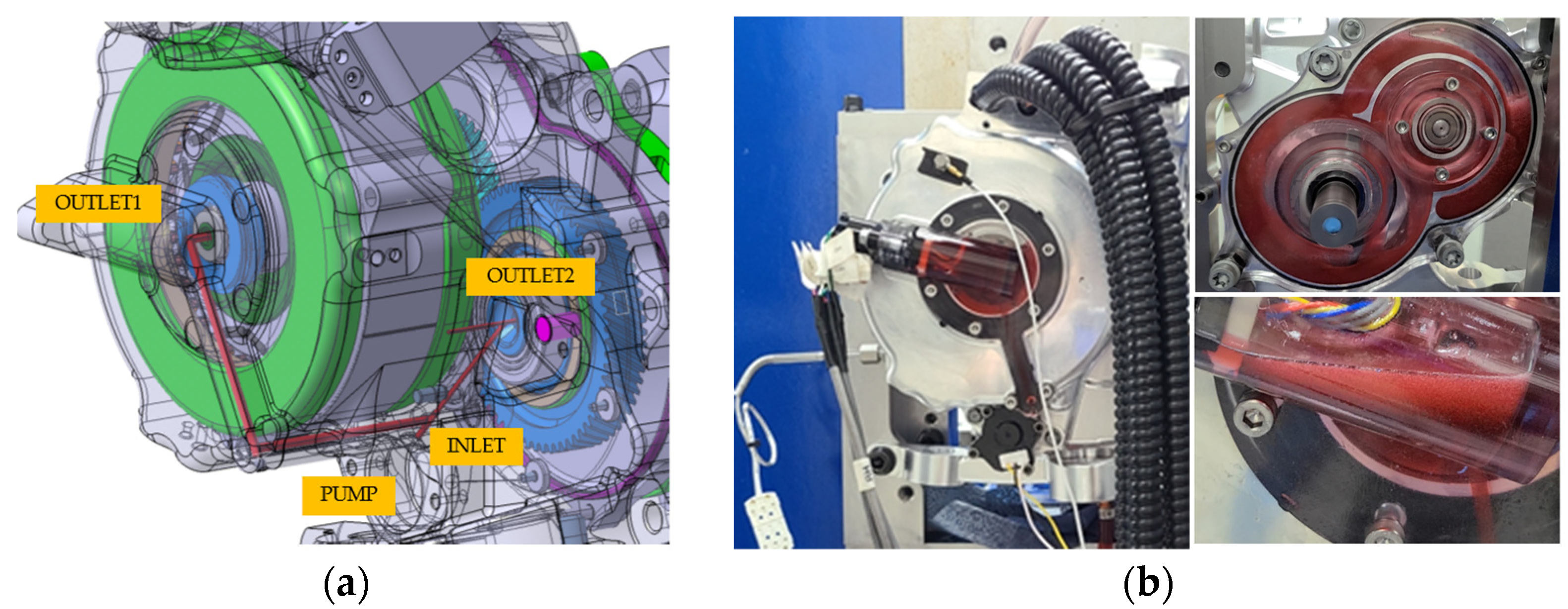
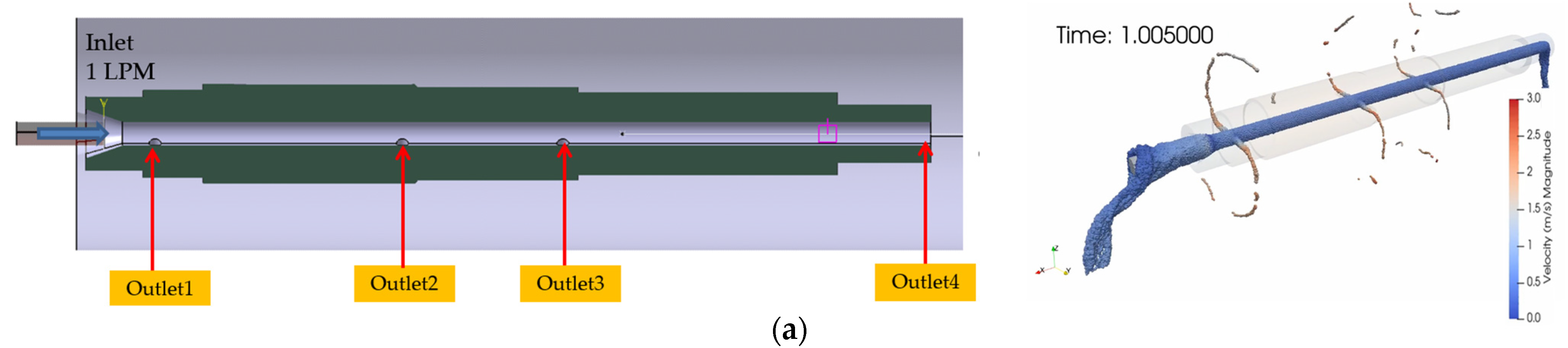
The internal lubrication flow of the system is designed so that oil supplied from the oil pump is divided into two branched flow paths: one directed to the first PGS and the other to the second PGS. The oil supplied to the first PGS flows through the hollow rotor shaft, lubricating the motor, PGS bearings, and the two OWCs. However, due to the location of the oil supply holes machined into the rotor shaft, oil is first delivered to the motor and PGS support bearings, potentially leading to an insufficient oil supply to the OWCs. To assess the oil distribution to the OWCs, a fluid dynamics analysis was conducted to evaluate the oil flow rates at the first planetary reducer flow path (OUTLET1) and the second planetary reducer flow path (OUTLET 2), as shown in Figure 12a. Additionally, experimental testing revealed an unaccounted-for factor in the analysis; oil churning caused by the rotation of external gears led to air bubble formation, which in turn resulted in a reduced oil supply within the rotor shaft. This phenomenon was confirmed through experimental validation, as illustrated in Figure 12b.
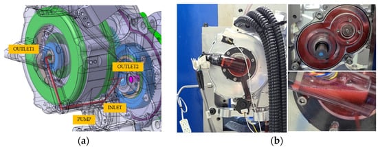
Figure 12.
(a) Oil flow analysis. (b) Supplied oil visualization.
To increase the oil supply to the one-way clutch (OWC), a particle-based fluid analysis (Nextflow) was conducted to evaluate the oil flow behavior and distribution during rotor shaft rotation, as shown in Figure 13a. The particle size was set to 0.4 mm for the simulation. The analysis results indicated that as rotor speed increased, a significant amount of oil escaped through the rotor oil inlet clearance, reducing oil supply to the rotor end (Outlet 4). Beyond approximately 4 s (8000 RPM), the oil supply at Outlet 4 was nearly depleted, and after 6 s, the oil supply to the OWC (Outlet 3) was also nearly depleted. Between 0 and 6000 RPM, the oil flow rate at Outlets 1 to 3 initially increased with rotor speed. However, as inflow through the rotor inlet decreased, a critical rotational speed threshold was reached, beyond which the oil flow at Outlets 1 to 3 also began to decrease. The oil flow distribution at each inlet is illustrated in Figure 13b. Based on the experimental and simulation results, the oil hole configuration in the rotor shaft was modified to redirect oil flow more effectively toward the rotor. As shown in Figure 13c, the oil holes were repositioned asymmetrically from both sides to a single-sided configuration to enhance oil distribution.
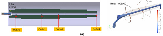
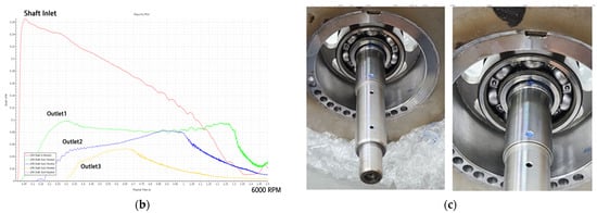
Figure 13.
(a) Oil flow according to rotational speed of rotor. (b) Changes in the amount of inlet/outlet oil over time. (c) Single sided oil holes in rotor shaft.
5. Results
5.1. Test of In-Wheel Assembly Performance
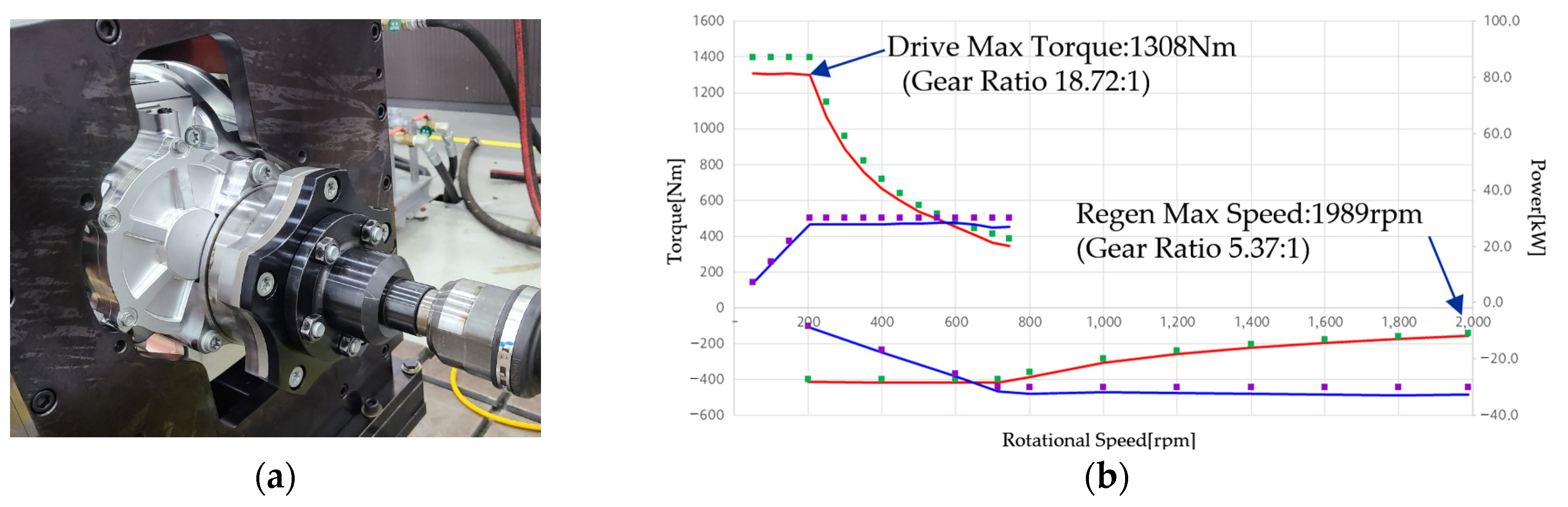
A prototype of the final designed variable speed-reduction in-wheel assembly was fabricated and subjected to functionality and performance testing using a dynamometer, as shown in Figure 14a. The T-N (torque–speed) characteristics were measured by applying maximum motor torque at various speeds. As illustrated in Figure 14b, the results confirmed a maximum driving torque of 1308 Nm and a maximum regenerative speed of 1989 rpm (equivalent to 270 km/h with a 19-inch wheel). The driving efficiency of the in-wheel assembly achieved an average of 81.4% with a peak efficiency of 88.1%, while the regenerative efficiency reached an average of 80% with a maximum efficiency of 85%. The efficiency map is presented in Figure 15. Furthermore, even at the maximum vehicle speed of 270 km/h, the rotor speed remained at 76% (10,681 rpm) of the motor’s speed limit, demonstrating the potential for further speed increases while also reducing motor drag during freewheeling operation.
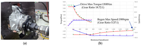
Figure 14.
Performance test for variable reducer in-wheel system. (a) Variable reducer in-wheel assay PT dynamo test. (b) Wheel T-N performance.
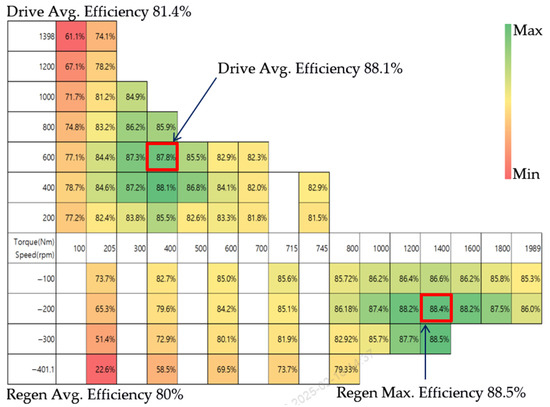
Figure 15.
Efficiency for variable reducer in-wheel system.
5.2. Simulation of Vehicle Performance
To evaluate the real-world performance of the variable speed-reduction in-wheel system, a vehicle dynamics simulation (CarMaker) was conducted, as illustrated in Figure 16. The motor specifications were set to 55 kW output power and a maximum speed of 16,000 rpm, referencing Toyota’s in-wheel system. The analysis compared the fixed-reduction in-wheel e-4WD and the variable speed-reduction in-wheel e-4WD under identical conditions. In the simulation, an IONIQ 5 was equipped with a direct-drive in-wheel motor (50 kW, 1500 Nm maximum torque) on the rear axle and a reduction-drive in-wheel motor on the front axle. The results showed that the variable speed-reduction in-wheel system improved longitudinal acceleration performance by 12.2% compared to the fixed-reduction system, achieving 0–100 km/h acceleration (zero to hundred) in 5.95 s, compared to 6.78 s for the fixed-reduction system.
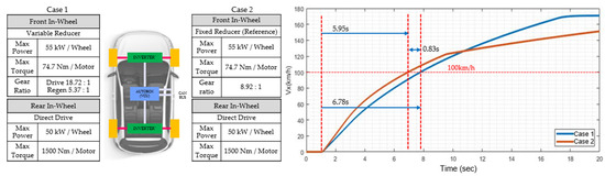
Figure 16.
Longitudinal dynamic performance analysis.
6. Conclusions
This study proposed a variable speed-reduction in-wheel assembly that enables e-4WD implementation in the front axle of FR vehicles while achieving high-performance vehicle-level driving characteristics without modifying the hard points. The paper described the mechanism characteristics, analysis, experimental results, and real-world performance of the proposed system, which integrates an efficient and compact hub bearing integrated reducer, PGS, and OWC into a novel clutch solution. The proposed variable speed-reduction in-wheel assembly achieved twice the maximum torque and a 35% increase in top speed compared to previously developed in-wheel systems. Additionally, real-world performance comparisons with Toyota’s in-wheel system demonstrated a 12.2% improvement in longitudinal acceleration performance.
Future research will focus on optimizing motor speed and torque control to develop an advanced control logic that ensures optimal gear-shifting performance across various driving conditions.
Author Contributions
Conceptualization, K.S.; car simulation, J.H.; writing—original draft, K.S.; writing—review and editing, K.S.; project administration, K.K. All authors have read and agreed to the published version of the manuscript.
Funding
This research received no external funding.
Data Availability Statement
The original contributions presented in this study are included in the article; further inquiries can be directed to the corresponding author.
Conflicts of Interest
Kyeong Ho Shin, Kyeong Jin Ko, and Jun Hwa Hwang are employees of Hyundai Mobis. The paper reflects the views of the scientists, and not the company.
References
- Aloeyi, E.F.; Ali, N.; Wang, Q. A Review of In-Wheel Motors for Electric Vehicle Propulsion. In Proceedings of the 2022 IEEE Transportation Electrification Conference and Expo, Asia-Pacific (ITEC Asia-Pacific), Haining, China, 28–31 October 2022; pp. 1–6. [Google Scholar] [CrossRef]
- Deepak, K.; Frikha, M.A.; Benômar, Y.; El Baghdadi, M.; Hegazy, O. In-Wheel Motor Drive Systems for Electric Vehicles: State of the Art, Challenges, and Future Trends. Energies 2023, 16, 3121. [Google Scholar] [CrossRef]
- Feng, S.; Magee, C.L. Technological development of key domains in electric vehicles: Improvement rates, technology trajectories and key assignees. Appl. Energy 2020, 260, 114264. [Google Scholar] [CrossRef]
- Takeuchi, T.; Shimoya, N.; Katsuyama, E. Longitudinal Vibration Suppression Control for In-Wheel Motor Vehicle Considering Velocity Dependent Tire Force. Trans. Soc. Automot. Eng. Jpn. 2021, 52, 293–298. [Google Scholar] [CrossRef]
- de Carvalho Pinheiro, H.; Galanzino, E.; Messana, A.; Sisca, L.; Ferraris, A.; Airale, A.G.; Carello, M. All-Wheel Drive Electric Vehicle Modeling and Performance Optimization. SAE Tech. Pap. 2020, 1–13. [Google Scholar]
- Jian, L. Research status and development prospect of electric vehicles based on hub motor. In Proceedings of the 2018 China International Conference on Electricity Distribution (CICED), Tianjin, China, 17–19 September 2018; pp. 126–129. [Google Scholar]
- Lee, S.; Ko, S.; Lee, S.; Kim, Y.; Cheon, J.; Kim, H. Development of Vehicle Stability Control Algorithm Using Torque Vectoring for In-wheel Independent Drive Vehicle. In Proceedings of the Korean Society of Automotive Engineers Fall Conference and Exhibition, Goyang, Republic of Korea, 20–23 November 2012; Korean Society of Automotive Engineers: Seoul, Republic of Korea, 2012; pp. 792–794. [Google Scholar]
- Lee, Y.; JunYoon, K.; Kim, D.; Lee, S.; Kim, D.; Jeon, J.W. Development of I-TCS Algorithm for In-Wheel Hybrid Vehicle. In Proceedings of the Korean Society of Automotive Engineers Fall Conference and Exhibition, Gyeongju, Republic of Korea, 20–23 November 2019; Korean Society of Automotive Engineers: Seoul, Republic of Korea, 2019; pp. 1159–1166. [Google Scholar]
- Shin, K.; Jeong, U.; Kim, D.; Kim, Y.; Lim, J. A Study on Tooth Micro-geometry Modification by Considering Gear Wear Pattern. In Proceedings of the Korean Society of Automotive Engineers Fall Conference and Exhibition, Jeju, Republic of Korea, 20–23 November 2024; Korean Society of Automotive Engineers: Seoul, Republic of Korea, 2022; pp. 10–16. [Google Scholar]
- Park, J.Y.; Na, S.; Cha, H.; Yi, K. Direct Yaw Moment Control with 4WD Torque-Vectoring for Vehicle Handling Stability and Agility. Int. J. Automot. Technol. 2022, 23, 555–565. [Google Scholar] [CrossRef]


Disclaimer/Publisher’s Note: The statements, opinions and data contained in all publications are solely those of the individual author(s) and contributor(s) and not of MDPI and/or the editor(s). MDPI and/or the editor(s) disclaim responsibility for any injury to people or property resulting from any ideas, methods, instructions or products referred to in the content. |
© 2025 by the authors. Published by MDPI on behalf of the World Electric Vehicle Association. Licensee MDPI, Basel, Switzerland. This article is an open access article distributed under the terms and conditions of the Creative Commons Attribution (CC BY) license (https://creativecommons.org/licenses/by/4.0/).