

Fabrication of TiO2 Nanotube Arrays by Progressive Anodization of Ti Thin Film on Insulated Substrates

 , ,
, ,  , and
, and 
Abstract
1. Introduction
- (i)
- Direct complexation with transported cations at the oxide electrolyte interface, preventing Ti(OH)xOy precipitation:
- (ii)
- Reaction with the oxide to form water-soluble [TiF6]2− complexes, leading to dissolution and breakdown of the barrier layer:
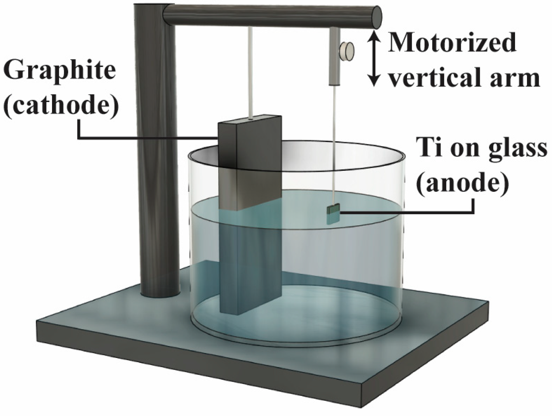
2. Materials and Methods
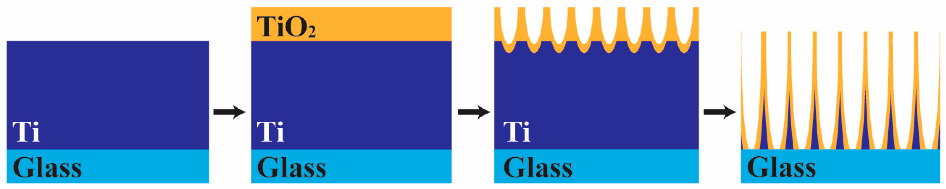
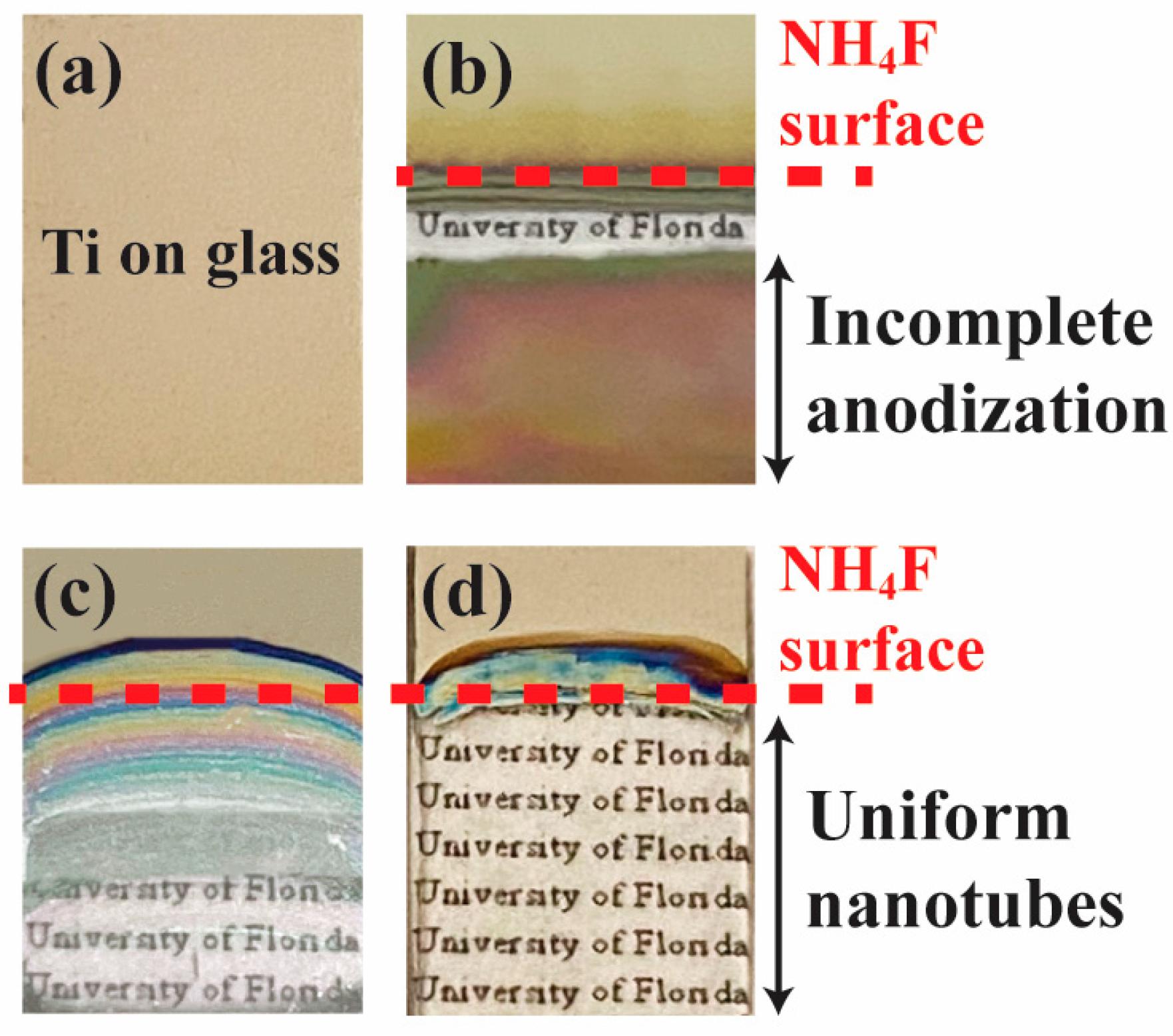
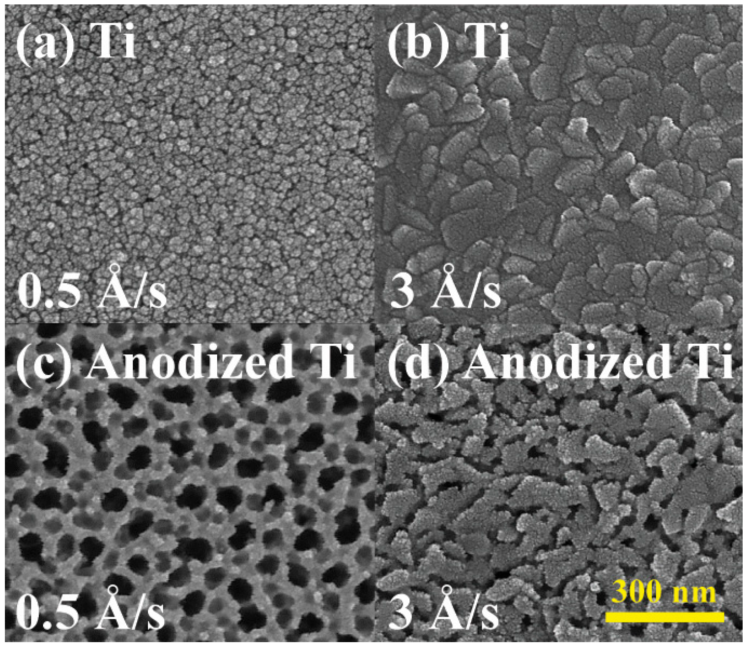
3. Results and Discussion
4. Conclusions
Author Contributions
Funding
Institutional Review Board Statement
Informed Consent Statement
Data Availability Statement
Conflicts of Interest
References
- Zhang, H.; Banfield, J.F. Structural Characteristics and Mechanical and Thermodynamic Properties of Nanocrystalline TiO2. Chem. Rev. 2014, 114, 9613–9644. [Google Scholar] [CrossRef]
- Abdellatif, S.; Sharifi, P.; Kirah, K.; Ghannam, R.; Khalil, A.; Erni, D.; Marlow, F. Refractive Index and Scattering of Porous TiO2 Films. Microporous Mesoporous Mater. 2018, 264, 84–91. [Google Scholar] [CrossRef]
- Han, W.; Wang, Y.D.; Zheng, Y. In Vitro Biocompatibility Study of Nano TiO2 Materials. Adv. Mater. Res. 2008, 47, 1438–1441. [Google Scholar] [CrossRef]
- Huang, Y.; Zheng, X.; Yin, Z.; Feng, T.; Fang, B.; Hou, K. Preparation of Nitrogen-Doped TiO2 Nanoparticle Catalyst and Its Catalytic Activity under Visible Light. Chin. J. Chem. Eng. 2007, 15, 802–807. [Google Scholar] [CrossRef]
- Mei, Z.-G.; Wang, Y.; Shang, S.; Liu, Z.-K. First-Principles Study of the Mechanical Properties and Phase Stability of TiO2. Comput. Mater. Sci. 2014, 83, 114–119. [Google Scholar] [CrossRef]
- Mergel, D.; Buschendorf, D.; Eggert, S.; Grammes, R.; Samset, B. Density and Refractive Index of TiO2 Films Prepared by Reactive Evaporation. Thin Solid Films 2000, 371, 218–224. [Google Scholar] [CrossRef]
- Roy, P.; Berger, S.; Schmuki, P. TiO2 Nanotubes: Synthesis and Applications. Angew. Chem. Int. Ed. 2011, 50, 2904–2939. [Google Scholar] [CrossRef]
- Wang, Y.; Wen, C.; Hodgson, P.; Li, Y. Biocompatibility of TiO2 Nanotubes with Different Topographies. J. Biomed. Mater. Res. A 2014, 102, 743–751. [Google Scholar] [CrossRef]
- Yang, L.; Luo, S.; Cai, Q.; Yao, S. A Review on TiO2 Nanotube Arrays: Fabrication, Properties, and Sensing Applications. Chin. Sci. Bull. 2010, 55, 331–338. [Google Scholar] [CrossRef]
- Zazpe, R.; Prikryl, J.; Gärtnerova, V.; Nechvilova, K.; Benes, L.; Strizik, L.; Jäger, A.; Bosund, M.; Sopha, H.; Macak, J.M. Atomic Layer Deposition Al2O3 Coatings Significantly Improve Thermal, Chemical, and Mechanical Stability of Anodic TiO2 Nanotube Layers. Langmuir 2017, 33, 3208–3216. [Google Scholar] [CrossRef]
- Zhou, Q.; Fang, Z.; Li, J.; Wang, M. Applications of TiO2 Nanotube Arrays in Environmental and Energy Fields: A Review. Microporous Mesoporous Mater. 2015, 202, 22–35. [Google Scholar] [CrossRef]
- Choi, J.; Wehrspohn, R.B.; Lee, J.; Gösele, U. Anodization of Nanoimprinted Titanium: A Comparison with Formation of Porous Alumina. Electrochim. Acta 2004, 49, 2645–2652. [Google Scholar] [CrossRef]
- Macµk, J.M.; Tsuchiya, H.; Schmuki, P. High-Aspect-Ratio TiO2 Nanotubes by Anodization of Titanium. Angew. Chem. Int. Ed. 2005, 44, 2100–2102. [Google Scholar] [CrossRef] [PubMed]
- Yao, C.; Webster, T.J. Anodization: A Promising Nano-Modification Technique of Titanium Implants for Orthopedic Applications. J. Nanosci. Nanotechnol. 2006, 6, 2682–2692. [Google Scholar] [CrossRef]
- LeClere, D.; Velota, A.; Skeldon, P.; Thompson, G.; Berger, S.; Kunze, J.; Schmuki, P.; Habazaki, H.; Nagata, S. Tracer Investigation of Pore Formation in Anodic Titania. J. Electrochem. Soc. 2008, 155, C487. [Google Scholar] [CrossRef]
- Sjöström, T.; Fox, N.; Su, B. Through-Mask Anodization of Titania Dot-and Pillar-like Nanostructures on Bulk Ti Substrates Using a Nanoporous Anodic Alumina Mask. Nanotechnology 2009, 20, 135305. [Google Scholar] [CrossRef]
- Sjöström, T.; Fox, N.; Su, B. A Study on the Formation of Titania Nanopillars during Porous Anodic Alumina Through-Mask Anodization of Ti Substrates. Electrochim. Acta 2010, 56, 203–210. [Google Scholar] [CrossRef]
- Albu, S.P.; Schmuki, P. Influence of Anodization Parameters on the Expansion Factor of TiO2 Nanotubes. Electrochim. Acta 2013, 91, 90–95. [Google Scholar] [CrossRef]
- David, T.M.; Dev, P.R.; Wilson, P.; Sagayaraj, P.; Mathews, T. A Critical Review on the Variations in Anodization Parameters toward Microstructural Formation of TiO2 Nanotubes. Electrochem. Sci. Adv. 2022, 2, e202100083. [Google Scholar] [CrossRef]
- Khudhair, D.; Bhatti, A.; Li, Y.; Hamedani, H.A.; Garmestani, H.; Hodgson, P.; Nahavandi, S. Anodization Parameters Influencing the Morphology and Electrical Properties of TiO2 Nanotubes for Living Cell Interfacing and Investigations. Mater. Sci. Eng. C 2016, 59, 1125–1142. [Google Scholar] [CrossRef]
- Omidvar, H.; Goodarzi, S.; Seif, A.; Azadmehr, A.R. Influence of Anodization Parameters on the Morphology of TiO2 Nanotube Arrays. Superlattices Microstruct. 2011, 50, 26–39. [Google Scholar] [CrossRef]
- Puga, M.; Venturini, J.; Ten Caten, C.; Bergmann, C. Influencing Parameters in the Electrochemical Anodization of TiO2 Nanotubes: Systematic Review and Meta-Analysis. Ceram. Int. 2022, 48, 19513–19526. [Google Scholar] [CrossRef]
- Qin, L.; Chen, Q.; Lan, R.; Jiang, R.; Quan, X.; Xu, B.; Zhang, F.; Jia, Y. Effect of Anodization Parameters on Morphology and Photocatalysis Properties of TiO2 Nanotube Arrays. J. Mater. Sci. Technol. 2015, 31, 1059–1064. [Google Scholar] [CrossRef]
- Yoriya, S.; Kittimeteeworakul, W.; Punprasert, N. Effect of Anodization Parameters on Morphologies of TiO2 Nanotube Arrays and Their Surface Properties. J. Chem. Chem. Eng. 2012, 6, 686. [Google Scholar]
- Tupala, J.; Kemell, M.; Harkonen, E.; Ritala, M.; Leskela, M. Preparation of Regularly Structured Nanotubular TiO2 Thin Films on ITO and Their Modification with Thin ALD-Grown Layers. Nanotechnology 2012, 23, 125707. [Google Scholar] [CrossRef]
- Tang, Y.; Tao, J.; Dong, Z.; Oh, J.T.; Chen, Z. The Formation of Micrometer-Long TiO2 nanotube Arrays by Anodization of Titanium Film on Conducting Glass Substrate. Adv. Nat. Sci. Nanosci. Nanotechnol. 2011, 2, 045002. [Google Scholar] [CrossRef]
- Sreekantan, S.; Saharudin, K.A.; Wei, L.C. Formation of TiO2 nanotubes via Anodization and Potential Applications for Photocatalysts, Biomedical Materials, and Photoelectrochemical Cell. IOP Conf. Ser. Mater. Sci. Eng. 2011, 21, 012002. [Google Scholar] [CrossRef]
- Sadek, A.Z.; Zheng, H.; Latham, K.; Wlodarski, W.; Kalantar-Zadeh, K. Anodization of Ti Thin Film Deposited on ITO. Langmuir 2009, 25, 509–514. [Google Scholar] [CrossRef]
- Li, Y.; Yu, X.; Yang, Q.; Sberveglieri, G. Fabrication of TiO2 Nanotube Thin Films and Their Gas Sensing Properties. J. Sens. 2009, 2009, 402174. [Google Scholar] [CrossRef]
- Yu, Y.; Zhao, Y.; Li, K.; Zhang, G.; Yu, K.; Ma, Y.; Li, Y. Microstructures and Optical Properties of TiO2/ZrO2 Nanotube/Nanoporous Heterofilm Prepared by Anodizing of Ti/Zr/Ti Multilayer Films. Appl. Surf. Sci. 2020, 503, 144316. [Google Scholar] [CrossRef]
- Xue, C.; Zhang, F.; Chen, S.; Yin, Y.; Lin, C. Tailoring the Surface Morphology of TiO2 Nanotube Arrays Connected with Nanowires by Anodization. Mater. Sci. Semicond. Process. 2011, 14, 157–163. [Google Scholar] [CrossRef]
- Wang, J.; Zhao, L.; Lin, V.S.-Y.; Lin, Z. Formation of Various TiO 2 Nanostructures from Electrochemically Anodized Titanium. J. Mater. Chem. 2009, 19, 3682–3687. [Google Scholar] [CrossRef]
- Perathoner, S.; Passalacqua, R.; Centi, G.; Su, D.S.; Weinberg, G. Preparation of TiO2 Nanopillar and Nanotube Array Thin Films. In Studies in Surface Science and Catalysis; Elsevier: Amsterdam, The Netherlands, 2007; Volume 172, pp. 437–440. ISBN 0167-2991. [Google Scholar]
- Macak, J.; Albu, S.; Kim, D.; Paramasivam, I.; Aldabergerova, S.; Schmuki, P. Multilayer TiO2–Nanotube Formation by Two-Step Anodization. Electrochem. Solid-State Lett. 2007, 10, K28. [Google Scholar] [CrossRef]
- Ji, Y.; Lin, K.-C.; Zheng, H.; Zhu, J.; Samia, A.C.S. Fabrication of Double-Walled TiO2 Nanotubes with Bamboo Morphology via One-Step Alternating Voltage Anodization. Electrochem. Commun. 2011, 13, 1013–1015. [Google Scholar] [CrossRef]
- Endut, Z.; Hamdi, M.; Basirun, W.J. Supercapacitance of Bamboo-Type Anodic Titania Nanotube Arrays. Surf. Coat. Technol. 2013, 215, 75–78. [Google Scholar] [CrossRef]
- Uhm, S.-H.; Lee, S.-B.; Song, D.-H.; Kwon, J.-S.; Han, J.-G.; Kim, K.-N. Fabrication of Bioactive, Antibacterial TiO2 Nanotube Surfaces, Coated with Magnetron Sputtered Ag Nanostructures for Dental Applications. J. Nanosci. Nanotechnol. 2014, 14, 7847–7854. [Google Scholar] [CrossRef]
- Shi, X.; Xu, Q.; Tian, A.; Tian, Y.; Xue, X.; Sun, H.; Yang, H.; Dong, C. Antibacterial Activities of TiO2 Nanotubes on Porphyromonas Gingivalis. RSC Adv. 2015, 5, 34237–34242. [Google Scholar] [CrossRef]
- Roguska, A.; Belcarz, A.; Zalewska, J.; Hołdyński, M.; Andrzejczuk, M.; Pisarek, M.; Ginalska, G. Metal TiO2 Nanotube Layers for the Treatment of Dental Implant Infections. ACS Appl. Mater. Interfaces 2018, 10, 17089–17099. [Google Scholar] [CrossRef]
- Li, T.; Wang, N.; Chen, S.; Lu, R.; Li, H.; Zhang, Z. Antibacterial Activity and Cytocompatibility of an Implant Coating Consisting of TiO2 Nanotubes Combined with a GL13K Antimicrobial Peptide. Int. J. Nanomed. 2017, 12, 2995–3007. [Google Scholar] [CrossRef]
- Kunrath, M.F.; Farina, G.; Sturmer, L.B.; Teixeira, E.R. TiO2 Nanotubes as an Antibacterial Nanotextured Surface for Dental Implants: Systematic Review and Meta-Analysis. Dent. Mater. 2024, 40, 907–920. [Google Scholar] [CrossRef]
- Calderon, P.d.S.; Rocha, F.R.G.; Xia, X.; Camargo, S.E.A.; Pascoal, A.L.d.B.; Chiu, C.-W.; Ren, F.; Ghivizzani, S.; Esquivel-Upshaw, J.F. Effect of Silicon Carbide Coating on Osteoblast Mineralization of Anodized Titanium Surfaces. J. Funct. Biomater. 2022, 13, 247. [Google Scholar] [CrossRef] [PubMed]
- Özkurt, Z.; Kazazoğlu, E. Zirconia Dental Implants: A Literature Review. J. Oral Implantol. 2011, 37, 367–376. [Google Scholar] [CrossRef] [PubMed]
- Osman, R.B.; Swain, M.V. A Critical Review of Dental Implant Materials with an Emphasis on Titanium versus Zirconia. Materials 2015, 8, 932–958. [Google Scholar] [CrossRef]
- Cionca, N.; Hashim, D.; Mombelli, A. Zirconia Dental Implants: Where Are We Now, and Where Are We Heading? Periodontol. 2000 2017, 73, 241–258. [Google Scholar] [CrossRef]
- Apratim, A.; Eachempati, P.; Salian, K.K.K.; Singh, V.; Chhabra, S.; Shah, S. Zirconia in Dental Implantology: A Review. J. Int. Soc. Prev. Community Dent. 2015, 5, 147–156. [Google Scholar] [CrossRef] [PubMed]
- Kniha, K.; Bock, A.; Peters, F.; Heitzer, M.; Modabber, A.; Kniha, H.; Hölzle, F.; Möhlhenrich, S. Aesthetic Aspects of Adjacent Maxillary Single-Crown Implants—Influence of Zirconia and Titanium as Implant Materials. Int. J. Oral Maxillofac. Surg. 2020, 49, 1489–1496. [Google Scholar] [CrossRef]
- Jum’ah, A.A.; Beekmans, B.; Wood, D.J. Zirconia Implants: The New Arrival in the Armoury of Successful Aesthetic Implant Dentistry. Smile Dent. J. 2012, 110, 1–20. [Google Scholar]
- Carrillo de Albornoz, A.; Vignoletti, F.; Ferrantino, L.; Cárdenas, E.; De Sanctis, M.; Sanz, M. A Randomized Trial on the Aesthetic Outcomes of Implant-supported Restorations with Zirconia or Titanium Abutments. J. Clin. Periodontol. 2014, 41, 1161–1169. [Google Scholar] [CrossRef]
- Gahlert, M.; Roehling, S.; Sprecher, C.; Kniha, H.; Milz, S.; Bormann, K. In Vivo Performance of Zirconia and Titanium Implants: A Histomorphometric Study in Mini Pig Maxillae. Clin. Oral Implants Res. 2012, 23, 281–286. [Google Scholar] [CrossRef]
- Depprich, R.; Zipprich, H.; Ommerborn, M.; Naujoks, C.; Wiesmann, H.-P.; Kiattavorncharoen, S.; Lauer, H.-C.; Meyer, U.; Kübler, N.R.; Handschel, J. Osseointegration of Zirconia Implants Compared with Titanium: An in Vivo Study. Head Face Med. 2008, 4, 1–8. [Google Scholar] [CrossRef]
- Sollazzo, V.; Pezzetti, F.; Scarano, A.; Piattelli, A.; Bignozzi, C.A.; Massari, L.; Brunelli, G.; Carinci, F. Zirconium Oxide Coating Improves Implant Osseointegration in Vivo. Dent. Mater. 2008, 24, 357–361. [Google Scholar] [CrossRef] [PubMed]
- Clever, K.; Schlegel, K.A.; Kniha, H.; Conrads, G.; Rink, L.; Modabber, A.; Holzle, F.; Kniha, K. Experimental Peri-Implant Mucositis around Titanium and Zirconia Implants in Comparison to a Natural Tooth: Part 1-Host-Derived Immunological Parameters. Int. J. Oral Maxillofac. Surg. 2019, 48, 554–559. [Google Scholar] [CrossRef]
- Su, E.; Justin, D.; Pratt, C.; Sarin, V.; Nguyen, V.; Oh, S.; Jin, S. Effects of Titanium Nanotubes on the Osseointegration, Cell Differentiation, Mineralisation and Antibacterial Properties of Orthopaedic Implant Surfaces. Bone Jt. J. 2018, 100, 9–16. [Google Scholar] [CrossRef]
- Hosseinpour, S.; Nanda, A.; Walsh, L.J.; Xu, C. Microbial Decontamination and Antibacterial Activity of Nanostructured Titanium Dental Implants: A Narrative Review. Nanomaterials 2021, 11, 2336. [Google Scholar] [CrossRef]
- Tang, Y.; Tao, J.; Zhang, Y.; Wu, T.; Tao, H.; Zhu, Y. Preparation of TiO2 Nanotube on Glass by Anodization of Ti Films at Room Temperature. Trans. Nonferrous Met. Soc. China 2009, 19, 192–198. [Google Scholar] [CrossRef]
- Kılınç, N.; Şennik, E.; Öztürk, Z.Z. Fabrication of TiO2 Nanotubes by Anodization of Ti Thin Films for VOC Sensing. Thin Solid Films 2011, 520, 953–958. [Google Scholar] [CrossRef]
- Mor, G.K.; Varghese, O.K.; Paulose, M.; Grimes, C.A. Transparent Highly Ordered TiO2 Nanotube Arrays via Anodization of Titanium Thin Films. Adv. Funct. Mater. 2005, 15, 1291–1296. [Google Scholar] [CrossRef]
- Yin, H.; Liu, H.; Shen, W. The Large Diameter and Fast Growth of Self-Organized TiO2 Nanotube Arrays Achieved via Electrochemical Anodization. Nanotechnology 2009, 21, 035601. [Google Scholar] [CrossRef] [PubMed]
- Wang, J.; Lin, Z. Freestanding TiO2 Nanotube Arrays with Ultrahigh Aspect Ratio via Electrochemical Anodization. Chem. Mater. 2008, 20, 1257–1261. [Google Scholar] [CrossRef]
- Regonini, D.; Bowen, C.R.; Jaroenworaluck, A.; Stevens, R. A Review of Growth Mechanism, Structure and Crystallinity of Anodized TiO2 Nanotubes. Mater. Sci. Eng. R Rep. 2013, 74, 377–406. [Google Scholar] [CrossRef]
- Prakasam, H.E.; Shankar, K.; Paulose, M.; Varghese, O.K.; Grimes, C.A. A New Benchmark for TiO2 Nanotube Array Growth by Anodization. J. Phys. Chem. C 2007, 111, 7235–7241. [Google Scholar] [CrossRef]
- Grimes, C.A. Synthesis and Application of Highly Ordered Arrays of TiO2 Nanotubes. J. Mater. Chem. 2007, 17, 1451–1457. [Google Scholar] [CrossRef]
- Yadav, M.; Shankar, A. Explore the Investigation of Structural and Morphological Characteristics of E-Beam Evaporated Copper Thin Film of Various Thicknesses; AIP Publishing: New York, NY, USA, 2024; Volume 3149. [Google Scholar]
- Wibowo, K.; Sahdan, M.; Asmah, M.; Saim, H.; Adriyanto, F.; Hadi, S. Influence of Annealing Temperature on Surface Morphological and Electrical Properties of Aluminum Thin Film on Glass Substrate by Vacuum Thermal Evaporator; IOP Publishing: Bristol, UK, 2017; Volume 226, p. 012180. [Google Scholar]
- Semaltianos, N. Thermally Evaporated Aluminium Thin Films. Appl. Surf. Sci. 2001, 183, 223–229. [Google Scholar] [CrossRef]
- Cai, K.; Müller, M.; Bossert, J.; Rechtenbach, A.; Jandt, K.D. Surface Structure and Composition of Flat Titanium Thin Films as a Function of Film Thickness and Evaporation Rate. Appl. Surf. Sci. 2005, 250, 252–267. [Google Scholar] [CrossRef]
- Bordo, K.; Rubahn, H.-G. Effect of Deposition Rate on Structure and Surface Morphology of Thin Evaporated Al Films on Dielectrics and Semiconductors. Mater. Sci. 2012, 18, 313–317. [Google Scholar] [CrossRef]
- Arshi, N.; Lu, J.; Lee, C.G.; Yoon, J.H.; Koo, B.H.; Ahmed, F. Thickness Effect on Properties of Titanium Film Deposited by Dc Magnetron Sputtering and Electron Beam Evaporation Techniques. Bull. Mater. Sci. 2013, 36, 807–812. [Google Scholar] [CrossRef]


| Condition | Process Parameters | Nanotube Size (nm) |
|---|---|---|
| Ti film deposition rates | 0.5 Å/s | 10 |
| 3 Å/s | 100 | |
| Anodization voltages | 30 V | 50 |
| 50 V | 80 | |
| 70 V | 100 | |
| 90 V | 120 | |
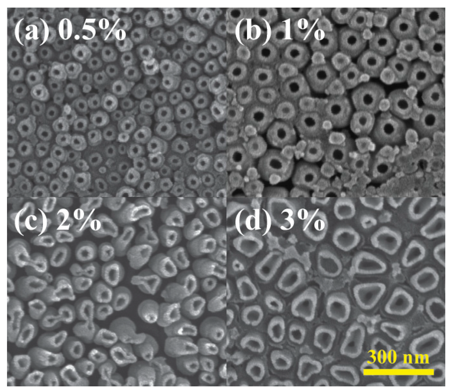
| NH4F concentrations | 0.5% | 50 |
| 1% | 80 | |
| 2% | 100 | |
| 3% | 120 | |
| Post-soaking in 3% NH4F | Pre-soaking | 50 |
| Post-soaking | 100 |
| Study | Substrate | Nanotube Size (nm) |
|---|---|---|
| This study | Glass (non-conductive) | 50–120 (optimized conditions) |
| [26] | ITO glass (conductive) | <100 |
| [57] | Ti thin film | ~60–90 |
| [58] | Ti thin film | ~30–50 |
Disclaimer/Publisher’s Note: The statements, opinions and data contained in all publications are solely those of the individual author(s) and contributor(s) and not of MDPI and/or the editor(s). MDPI and/or the editor(s) disclaim responsibility for any injury to people or property resulting from any ideas, methods, instructions or products referred to in the content. |
© 2025 by the authors. Licensee MDPI, Basel, Switzerland. This article is an open access article distributed under the terms and conditions of the Creative Commons Attribution (CC BY) license (https://creativecommons.org/licenses/by/4.0/).
Share and Cite
Chiang, C.-C.; Li, J.-S.; Wan, H.-H.; Ren, F.; Esquivel-Upshaw, J.F. Fabrication of TiO2 Nanotube Arrays by Progressive Anodization of Ti Thin Film on Insulated Substrates. Materials 2025, 18, 1219. https://doi.org/10.3390/ma18061219
Chiang C-C, Li J-S, Wan H-H, Ren F, Esquivel-Upshaw JF. Fabrication of TiO2 Nanotube Arrays by Progressive Anodization of Ti Thin Film on Insulated Substrates. Materials. 2025; 18(6):1219. https://doi.org/10.3390/ma18061219
Chicago/Turabian StyleChiang, Chao-Ching, Jian-Sian Li, Hsiao-Hsuan Wan, Fan Ren, and Josephine F. Esquivel-Upshaw. 2025. "Fabrication of TiO2 Nanotube Arrays by Progressive Anodization of Ti Thin Film on Insulated Substrates" Materials 18, no. 6: 1219. https://doi.org/10.3390/ma18061219
APA StyleChiang, C.-C., Li, J.-S., Wan, H.-H., Ren, F., & Esquivel-Upshaw, J. F. (2025). Fabrication of TiO2 Nanotube Arrays by Progressive Anodization of Ti Thin Film on Insulated Substrates. Materials, 18(6), 1219. https://doi.org/10.3390/ma18061219