Abstract
This paper reports the results of a study examining the effect of thermomechanical interactions that occur during a milling process conducted at a maximum axial depth of cut for a thin wall made of aluminium alloy 7050 T7451. The impact of cutting speed and wall thickness on cutting force and cutting temperature was determined. Response surface methodology and face-centred central composite design were used. It was found that raising the cutting speed to approximately vc ≈ 700 m/min led to an increase in cutting force component Fx and cutting temperature T, followed by a decrease in their values. Nonetheless, the values of these variables were considerably higher than those observed at vc = 300 m/min. The thinnest tested wall of t = 1 mm exhibited the greatest process instability and evident signs of chatter, while a wall thickness increase to t = 2 mm resulted in improved process stability and reduced flatness deviation. The interaction between the cutting force and the cutting temperature, as well as the occurrence of chatter, were established as two dominant factors affecting thin wall machining accuracy. Results showed that the assumed empirical models could be used to predict the tested dependent variables under similar milling conditions.
Keywords:
milling; thin-walled element; aluminium alloy; cutting force; cutting temperature; deformation; chatter; ANOVA; RSM; DoE 1. Introduction
In recent years, the aircraft industry has increasingly focused on finding solutions to reduce aircraft weight while at the same time increasing their reliability and operational efficiency [,]. Integral thin-walled components play a key role in this regard, as they are characterised by a relatively high strength [] and are subject to narrow dimensional and geometric tolerances []. Their application contributes to a decrease in fuel consumption, which has a direct impact on reducing operating costs []. Thin-walled structural parts used in aircraft design include: stringers, ribs, frames, spars, shells, bulkheads, and skin panels [,]. Depending on their type and intended use, such elements are mainly made of light metal alloys, especially aluminium alloys [], titanium alloys [], and sometimes magnesium alloys []. Composite materials offer an alternative to light metal alloys [], but their fabrication poses many problems []. Milling is the main method of machining thin-walled components for aircraft []. Given that these parts are designed to have a uniform structure [], rolled plates are currently applied as semi-finished products, with more than 90% of a rolled plate becoming chips after machining [,]. It is reported that the buy-to-fly ratio (i.e., a ratio of the weight of the semi-finished product to the weight of the manufactured part) for such cases is up to 30:1 []. It helps avoid additional assembly operations and allows the production of a monolithic structure that once consisted of up to several hundred parts [].
The machining of elements with thin walls requires a special technological approach. This is primarily related to the low rigidity of such components [] and the resulting susceptibility to post-machining deformation [] as well as chatter, which are the most commonly seen and troublesome problems [,]. Their occurrence makes it difficult to achieve both the appropriate dimensional and shape accuracy and the required surface quality []. As a result, companies are often forced to make corrections or scrap defective parts, which leads to increased manufacturing costs [,]. Despite these difficulties, the machining of thin-walled elements remains an economically viable solution, and the optimisation of process conditions is one of the key directions of research in this area []. It should be noted that the industry is intensively searching for new solutions that would simultaneously increase the efficiency of milling thin-walled components and minimise post-machining deformation. In this context, a variety of approaches are used, including the selection of a suitable machining strategy [], tool path optimisation [], selection of specified cutting parameters [] or high-speed cutting parameters [], and innovative methods of clamping the workpiece in the chuck []. Cutting tool manufacturers [,] have proposed specialised cutting tool designs, including end mills with varied blade pitch and variable helical angle for milling high and thin walls over their entire height (this process is also known as milling at a maximum axial depth of cut). This leads to more efficient tool use, shorter machining times, lower production costs, and higher process efficiency.
The development of advanced cutting tool designs and modern machining strategies has not eliminated the post-machining deformation of thin-walled components, which still poses a significant difficulty in industry. The main source of this problem is residual stress [], which is why its root causes are studied all over the world. Residual stress can be classified into: initial residual stress (or bulk residual stress) and machining-induced residual stress []. Yiyang et al. [] found that during the manufacture of a semi-finished product, external forces and temperature led to the formation of initial residual stress in the workpiece. Due to material removal during the machining process, the existing residual stress is released and redistributed, and the machining-induced residual stress is generated. It contributes to the creation of a new state of equilibrium and a new distribution of the residual stress. Kuczmaszewski et al. [] emphasised that machining-induced residual stress is typically attributed mainly to the effects of the cutting force and the heat generated in the cutting zone. For this reason, two basic models of machining-induced residual stress formation are distinguished: a mechanical model related to the action of the cutting force and a thermal model which is related to the interaction of heat. However, it should be emphasised that these are simplified models, as the first one omits the influence of temperature, while the other one does not take into account the impact of cutting force []. In a real machining process, the workpiece undergoes deformation due to the impact of high loads, high strain rates, and friction between the tool and the machined surface. In addition to that, the machining-generated heat is of vital importance, since a non-uniform distribution of that heat leads to the occurrence of temperature gradients in the machined layer. This may trigger local phase transitions and microstructure modifications, affecting the state of stress in the workpiece [,]. Importantly, as for stress located in the surface layer, compressive stress is predominantly caused by the action of cutting force, whereas tensile stress results from temperature effects []. As mentioned previously, complex thermomechanical interactions occur during the machining process. The value and sign of residual stress in the material therefore depend on both factors, as well as on which one of them is dominant []. Ma et al. [] claim that researchers predominantly present residual stress as a function of machining parameters, emphasising that residual stress should be considered primarily as a result of combined mechanical and thermal interactions. Table 1 shows a comparison of initial residual stress and machining-induced residual stress.

Table 1.
Comparison of initial residual stress and machining-induced residual stress.
One of the main issues in the milling of thin-walled elements is chatter, which is a serious and undesirable phenomenon affecting the quality of manufactured parts []. Chatter occurs as a dynamic response of the workpiece–tool–chuck–machine tool system to the force acting on this system []. As thin-walled structures are characterised by low rigidity, even a slight disturbance in the cutting force can lead to a dynamic instability and a rapid increase in chatter amplitude. The effects of this phenomenon are particularly significant, as the resulting deformation of parts often makes it impossible to meet the required tolerances [,,]. Chatter leads to reduced surface quality, the formation of characteristic marks known as chatter marks, as well as element damage. A prolonged impact of chatter can also cause faster tool wear and lower dimensional and shape accuracy of products [,].
The objective of this research is to evaluate the thermomechanical interaction occurring during thin wall milling at a maximum axial depth of cut. The study focuses on identifying and evaluating the impact of wall thickness and cutting speed on cutting force as well as cutting temperature. This study is a continuation of the author’s previous research on thin wall milling at a maximized axial depth of cut [], in which particular attention was devoted to analysing the influence of wall thickness and cutting speed on the post-machining deformation and residual stress formation. To clarify the physical foundations of the observed effects, it was necessary to concentration on the thermomechanical interactions occurring during machining. The problem of these interactions constitutes the main subject matter of this paper. These investigations are part of a broader research cycle aimed at developing a comprehensive understanding of the mechanisms that govern the quality of thin-walled components that were milled with a maximized axial depth of cut.
2. Materials and Methods
Figure 1 shows the design of the experiment. A thin-walled sample with variable wall thickness, made of aluminium alloy 7050 T7451, was the object of the study. Experimental independent variables were thin wall thickness and cutting speed. Dependent variables related to thermomechanical interactions in the milling process were cutting force and cutting temperature. Constant factors included other technological parameters (feed per tooth, axial depth of cut, and radial depth of cut (milling width)), as well as cutting tools. Disturbing factors were chatter, tool wear, and tool deflection.
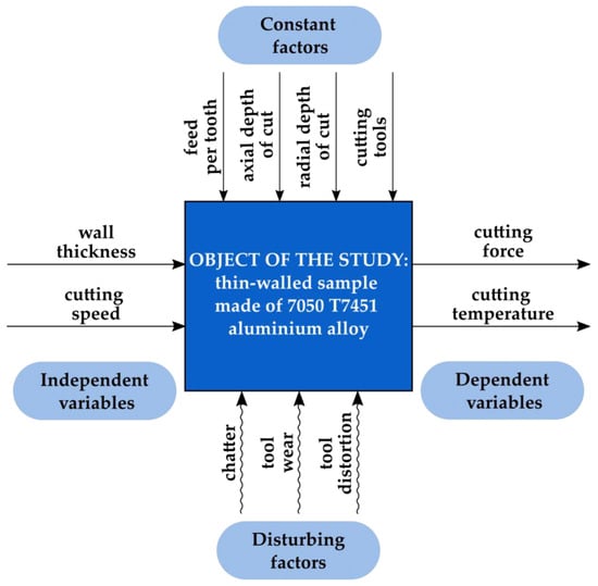
Figure 1.
Design of the experiment.
The experimental setup with all key components is shown in Figure 2. It included a CNC machine tool on which the cutting process was performed, as well as cutting tools selected according to the material properties and geometries of the workpiece. The figure also shows a sample before machining, as well as a milled part. The apparatus for examining thermal and mechanical interactions during the cutting process, including a dynamometer for measuring cutting force components and a stand for measuring cutting temperature using a natural thermocouple, was also presented. This approach allowed for a comprehensive investigation of both mechanical and thermal aspects of the cutting process, as well as a detailed interpretation of the obtained results.
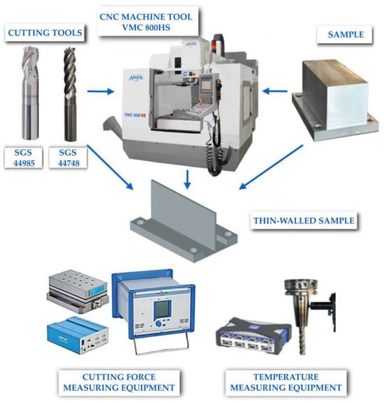
Figure 2.
Experimental setup.
The study was conducted in accordance with the design of experiments (DoE) procedure, which is an effective analytical tool for experimental design and analysis of experimental results, i.e., the development of a mathematical model that best fits the experimental data. Such an approach allows for the assessment of the impact of the independent variables on the dependent variables under study. It aims to obtain as much useful information as possible at minimal cost []. For this purpose, the specialist Design-Expert® (23.1.8) software was applied, enabling comprehensive statistical analysis and visual processing of measurement data. The study employed response surface methodology (RSM), which is based on statistics and used for designing experiments and optimising process variables [,,]. A face-centred central composite design (FCCCD) was selected to ensure a uniform distribution of experimental points in the experimental domain. Based on the applied design of experiment, requiring three variability levels for each test, the optimal number of indispensable experimental trials was set to 13. As required, the central point was replicated 5 times. Table 2 lists independent variables and their coded levels used in the face-centred central composite design. The variables were denoted by: A—wall thickness, and B—cutting speed. Each variable was coded at three levels: low (−1), medium (0), and high (+1).
Table 2.
Independent variables and their coded levels for the face-centred central composite design (FCCCD).
The thin-walled samples were made of 7050 T7451 aluminium alloy, compliant with all the technical standards in the AMS4050K specification. This material exhibits very high strength and good resistance to corrosion cracking, particularly stress-corrosion cracking. The 7050 T7451 alloy is primarily used in aircraft applications for the production of fuselage, wing skin, frame, and other load-bearing structural components. The chemical composition and selected mechanical properties of this material are given in Table 3.
Table 3.
Chemical composition and selected mechanical properties of the 7050 T7451 alloy (compiled based on []).
A rolled plate with a thickness of 50 mm was a semi-finished product. It was used to fabricate rectangular samples with the dimensions of 100 mm × 65 mm (length × width). The pretreatment involved preparing the workpiece for mounting in a specially designed mounting plate by means of screw joints, in order to ensure mounting repeatability and stability. Following the proper treatment, a thin wall with a height of 48 mm (which resulted from leaving a 2 mm thick base) and a variable thickness of 1 mm, 1.5 mm, and 2 mm was obtained.
Milling was conducted on the CNC Avia VMC 800HS machining centre. First of all, roughing was performed with constant technological parameters. The radial depth of cut (milling width) was adjusted in such a way that the finishing allowance value was the same, whatever the wall thickness. Finishing was carried out at a maximized axial depth of cut in two passes of the tool, one per side (Figure 3). It must be emphasised that both operations were performed as dry down-milling. Technological parameters of roughing and finishing operations are listed in Table 4.
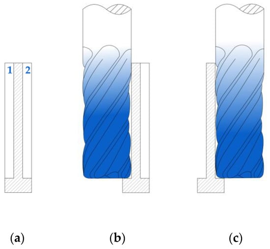
Figure 3.
Finish milling of a thin wall at a maximized axial depth of cut: (a) wall before finishing, tool passes are denoted by 1 and 2; (b) first pass of the tool; (c) second pass of the tool.
Table 4.
Technological parameters of roughing and finishing operations.
The milling was conducted with the application of two cutting tools from KYOCERA SGS Precision dedicated to high-performance machining of aluminium alloys. Roughing was performed with a 44985 end mill, whereas finishing was performed with a 44748 end mill designed for thin wall machining at a maximum axial depth of cut. In both operations, ERICKSON AHPVTTMQL1C heat shrink tool holders 16090M (44985) and 12090M (44748) with an HSK63 tool taper were applied. They are manufactured by M & J Tooling LLC (M & J Tooling LLC, Dayton, OH, USA). It should be noted that the condition of the cutting edges was carefully inspected after the machining of each specimen using a Keyence VHX-5000 microscope (Keyence Corporation of America, Itasca, IL, USA). Detailed technical parameters of the end mill used for finishing are given in Table 5.
Table 5.
Detailed technical parameters of cutting tools used for roughing and finishing.
The study on the thermomechanical interactions occurring during thin wall milling at a maximized axial depth of cut focused on two dependent variables, i.e., the cutting force and the cutting temperature. Figure 4 shows a measuring stand that was located in the CNC machine tool workspace. Measurements of the cutting force components (Fx, Fy, Fz) were made using a piezoelectric dynamometer Kistler 9257B (Kistler, Winterthur, Switzerland) that was mounted directly on the machine tool table. To its upper part, a mounting plate with a workpiece was fixed by screw joints. The measuring stand also comprised a signal amplifier Kistler 5070A (Kistler, Winterthur, Switzerland) and a data acquisition module DAQ 5697A (Kistler, Winterthur, Switzerland). Measurement data were processed in the DynoWare (type 2825A) software. The cutting temperature was measured on a specially designed measuring stand based on a natural thermocouple effect produced by the end mill and the workpiece. In this effect, a contact between two different materials—tool blade material and workpiece material—creates a thermocouple junction that generates an electromotive force proportional to the cutting temperature. According to the law of homogeneity for thermocouple junctions, the introduction of an additional conductive material into the thermocouple circuit does not affect the measurement, as long as both of its ends remain at the same temperature. Therefore, the use of supplementary components, i.e., the graphite brush, the copper washer, and the measurement cables transmitting the signal between the thermocouple junction and the amplifier, enabled signal acquisition without distortion of the results. Owing to the holder design with an integrated spring, the graphite brush remained pressed against the tool, ensuring a stable and disturbance-free electrical contact. The copper washer was placed beneath the dynamometer to isolate the system, which was necessary due to the complexity of the measurement setup. The obtained signal was transmitted to an amplifier HBM 1-MX840A (Hottinger Brüel & Kjær, Darmstadt, Germany) and recorded on a personal computer using the CatmanEasy (V35.1) software. The amplifier allowed for a high sampling frequency. For this case, 10,000 Hz was applied. Additionally, a dedicated stand was developed to calibrate the natural thermocouple formed by a sintered carbide (cutting tool material)—aluminium alloy (workpiece material) pair. The calibration data were used to establish a relationship between the electromotive force and the temperature. The calibration setup consisted of a natural thermocouple made of rods corresponding to the tool and workpiece materials. The thermocouple was placed inside a thermally insulated chamber equipped with heaters, and a reference thermocouple was attached at the junction of the two rods. The electromotive force generated by the natural thermocouple was recorded using the amplifier HBM 1-MX840A (Hottinger Brüel & Kjær, Darmstadt, Germany), while the temperature from the reference thermocouple was read with a multimeter MY-64 (XTREME, Stary Puznów, Poland). The calibration points were fitted with a fourth-degree polynomial, producing a coefficient of determination of R2 = 0.9970. The resulting relationship is presented in Equation (1):
where y—temperature in the cutting zone at the tool–workpiece interface [°C], x—electromotive force at the interface between the tool and workpiece materials [V].
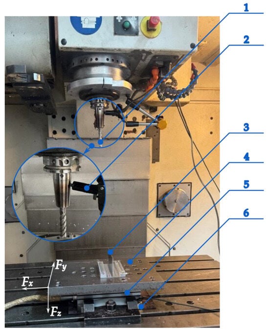
Figure 4.
Stand for measuring cutting force components and cutting temperature (CNC machine tool workspace): 1—cutting tool (first junction of a natural thermocouple), 2—graphite brush, 3—workpiece (second junction of a natural thermocouple), 4—mounting plate, 5—dynamometer, 6—copper washer.
Moreover, considering the author’s research presented in work [], which related to thin wall milling at a maximized axial depth of cut and involved the analysis of the post-machining deformations, it was decided that the time curve of the cutting force component Fx with the flatness deviation would be compared. These measurements were carried out using the Zeiss Contura 7/10/6 coordinate (Zeiss, Oberkochen, Germany) measuring machine, compatible with the Calypso (7.6.04) software and equipped with a VAST XT GOLD scanning probe (Zeiss, Oberkochen, Germany). A stylus with a 3 mm tip diameter was used. The obtained flatness deviation results are visualised in 3D form.
The methodology applied in this study made it possible to examine in detail the thermal and mechanical interactions occurring during thin wall milling at a maximized axial depth of cut. In effect, it was possible to establish detailed relationships between tested variables.
The experimental design and results of the face-centred central composite design (FCCCD) are presented in Table A1.
3. Results
3.1. Cutting Force Components
The next stage of the analysis of the results was the assessment of cutting force, which is an important criterion for describing the milling process. The cutting force reflects the real interaction conditions between the tool and the workpiece, and the examination of its behaviour pattern allows for the assessment of both material removal efficiency and machining system stability. For a more in-depth understanding of the cutting force components, Figure 5 shows a diagram illustrating the cutting tool path during thin wall finishing at a maximized axial depth of cut.
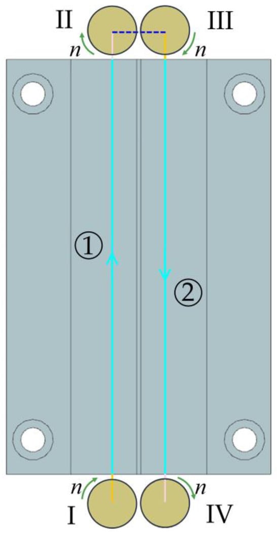
Figure 5.
Cutting tool path during thin wall finishing at a maximized axial depth of cut: 1—first pass of the tool, 2—second pass of the tool, I and II—entry and exit of the tool during first pass, III and IV—entry and exit of the tool during second pass.
The machining operation was performed in two concurrent tool passes, denoted by numbers 1 and 2, respectively. Firstly, the tool made the first pass along the surface of the wall on the left side, in accordance with the assumed feed direction (marked with a blue arrow), starting from Point I, i.e., the tool entry into the material, until reaching Point II, marking the tool exit from the material after completing the first pass. After that, the tool made a second pass on the opposite side of the wall (on the right), in the reverse direction to the first pass (in accordance with the feed direction). Here, Point III marks the entry of the tool into the material during the second pass, while Point IV marks the moment when the tool exits the material after completing the machining. Green arrows indicate the direction of tool rotation.
Figure 6 and Figure 7 show examples of time curves for individual cutting force components: Fx (Figure 6a and Figure 7a), Fy (Figure 6b and Figure 7b), and Fz (Figure 6c and Figure 7c) for two tested wall thicknesses, t = 1 mm and t = 2 mm, for cutting speed vc = 300 m/min. The real-time recording of cutting force component signals allowed for observation of the cutting process dynamics and identification of load variations over time. An analysis of the curves indicates the occurrence of two cutting tool passes. The first pass takes place on the left side of the wall—following the orientation of the machine tool y-axis, while the second pass takes place on the right side of the wall, i.e., in the reverse direction to the y-axis of the machine tool. This method of performing the process results in a change in the direction of the cutting force, which was recorded in the form of a change in sign (from negative to positive) of the Fx and Fy components. It should be emphasised that clear differences were observed in the curves obtained for these two cutting force components between the first and the second pass of the cutting tool. The first tool pass is characterised by greater stability, and there are no sudden jumps in the values of the cutting force components. In the second pass, however, the behaviour of the cutting force components becomes more unstable—there are numerous jumps in values and amplitude fluctuations, which suggests more difficult cutting conditions. The curves of the cutting force components Fx and Fy, especially of Fx, show the presence of characteristic extremes, indicating temporary instabilities of the cutting process. This phenomenon can probably be linked to the occurrence of chatter, which results from the interaction between the cutting force and the dynamic susceptibility of the workpiece–tool–chuck–machine tool system. Additionally, when comparing the curves for the two analysed wall thicknesses (t = 1 mm and t = 2 mm), significant differences in the nature of the signal can be observed. For the thickness t = 1 mm, two distinct extremes are visible, while for t = 2 mm, only one such extreme was observed, which indicates a higher rigidity of this wall. The behaviour patterns of the components Fx and Fy at t = 1 mm are therefore characterised by greater instability and more dispersed signal fluctuations, while for a thickness of t = 2 mm, the variations are more orderly and regular. However, it is worth noting that the maximum values of the cutting force components (without taking into account temporary extremes) were higher for the thickness t = 2 mm. The cutting force component Fz has the least substantial effect on the cutting process due to the lowest values (in comparison to Fx and Fy). It should also be emphasised that the repeatability of the time curves for these cutting force components was confirmed via the central point runs according to FCCCD.
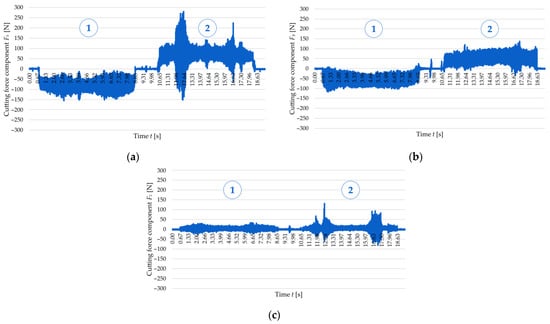
Figure 6.
Variations in the cutting force components for a cutting speed of vc = 300 m/min and a wall thickness of t = 1 mm: (a) Fx; (b) Fy; (c) Fz: 1—first tool pass, 2—second tool pass.
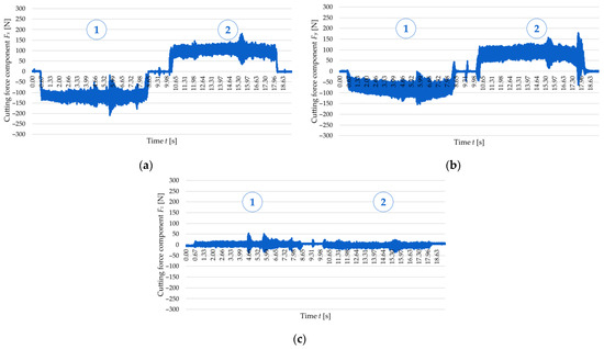
Figure 7.
Variations in the cutting force components for a cutting speed of vc = 300 m/min and a wall thickness of t = 2 mm: (a) Fx; (b) Fy; (c) Fz: 1—first pass of the tool, 2—second pass of the tool.
To establish a relationship linking the cutting force with the accuracy of manufactured thin walls, Figure 8 and Figure 9 show the correlation between the time curve of the Fx observed for the second pass of the end mill at a cutting speed of vc = 300 m/min and the post-machining deformation of the thin walls with thicknesses t = 1 mm and t = 2 mm, respectively. The post-machining deformation was defined as a flatness deviation from the ideal reference plane (marked by pink outline). First, the focus was put on the wall with a thickness of t = 1 mm (Figure 8), and an analysis of the graphical representation of flatness deviation revealed a significant distortion of the wall. Next, the flatness deviation was shown in a top view, overlaid with a time curve of the Fx for the second pass of the cutting tool, which was deliberately reversed to illustrate how the component varied depending on the milling path. In this way, it is possible to establish a correlation between two characteristic vertical marks (orthogonal to the tool feed direction) on the surface of a thin wall resulting from chatter, as well as the increased value and amplitude of the cutting force component Fx. After that, a wall with a thickness of t = 2 mm was considered in the same way (Figure 9); for this case, the post-machining deformation of the wall was considerably smaller (compared to the wall thickness t = 1 mm). An analysis of the top view of the graphical representation of flatness deviation, combined with the time curve of the cutting force component Fx demonstrates that the flatness deviation is significantly smaller and that the Fx component curve is more stable. In addition, one characteristic vertical mark can be observed on the wall surface, which is related to the nature of variations in the cutting force component Fx. In summary, the results obtained for the two tested wall thicknesses showed a clear correlation between the cutting force component Fx and the post-machining deformation of the wall.
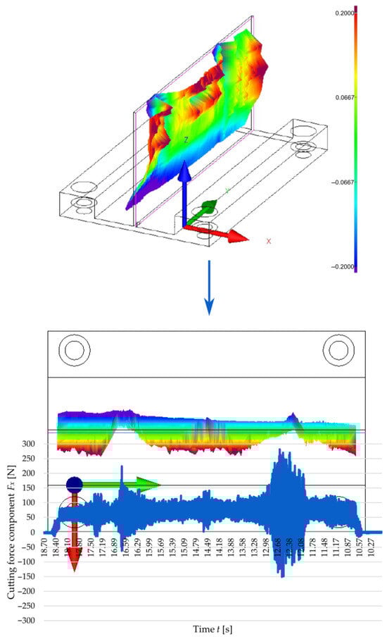
Figure 8.
Correlation between the cutting force component Fx during the second pass of the end mill at a cutting speed of vc = 300 m/min and a 3D visualisation of the flatness deviation in a thin wall with a thickness of t = 1 mm.
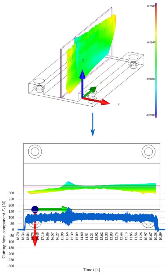
Figure 9.
Correlation between the cutting force component Fx during the second pass of the end mill at a cutting speed of vc = 300 m/min and a 3D visualisation of the flatness deviation in a thin wall with a thickness of t = 2 mm.
The next stage of the cutting force analysis was a quantitative assessment using mathematical modelling elements. The following part of this study offers a detailed analysis of Fx, as this component had the most significant impact on the quality of thin walls. Its maximum values were evaluated, omitting the characteristic extremes resulting from temporary instabilities of the machining process due to chatter. For a more accurate description of the process, a separate analysis was carried out for two passes of the cutting tool, denoting them by Fx1 (first pass) and Fx2 (second pass), respectively. This approach resulted from noticeable differences in the values of the cutting force component Fx between these two passes. First, a statistical analysis of the experimental data for the first pass of the cutting tool was performed, and an empirical equation was determined to predict the value of the cutting force component Fx1 as a function of two independent variables, i.e., cutting speed and wall thickness. This was performed via analysis of variance (ANOVA), which allows for the assessment of the significance of the impact of individual factors and the adjustment of a regression function. On this basis, it was found that the best fit to the experimental data was obtained for the quadratic model. The quality of the fit was assessed using the coefficients of determination:
- R2 = 0.9946;
- Adjusted R2 = 0.9907;
- Predicted R2 = 0.9675.
It should be emphasised that the difference between the predicted R2 and adjusted R2 values was less than 0.2, which indicates a good fit between the predictive model and the fitted model. In addition, the value of the determination coefficient R2 was close to 1. This indicates a very good fit of the empirical model to the experimental data. The high adequate precision value amounting to 44.2974 confirms the good signal-to-noise ratio, which is additional proof of the model’s reliability and its capacity to accurately replicate the relationship between independent and dependent variables. Ultimately, an empirical regression model was obtained describing the relationship between the cutting force component Fx1 relative to the cutting speed and wall thickness, expressed via Equation (2) using coded variables:
To verify the correctness and reliability of the developed model, a statistical verification was carried out using ANOVA for the adopted quadratic response surface model. This analysis allowed for the assessment of the statistical significance of the entire model and its individual components, as well as for determining the degree of fit of the model to the experimental data. The ANOVA results demonstrated the model’s F-value of 258.03, thus providing the model’s statistical significance. There was only a 0.01% probability that such a high F-value could occur by chance, i.e., as a result of measurement noise or random factors unrelated to the variables under study. This means that the wall thickness and the cutting speed have a significant impact on the shape of the response surface, and thus on the value of the Fx1. A further analysis of the p-value confirmed that most model terms were statistically significant because they met the criterion p < 0.05. This means that the corresponding factors have a real impact on variations in the cutting force component Fx1. It has been shown that both independent variables have a significant and strong impact on the Fx1 during the first pass of the tool. The only exception is factor A2 (the square component of the variable describing wall thickness), which did not reach the statistical significance level. This indicates that the influence of wall thickness on Fx1 is mainly linear and that non-linear relationships (of second order) are less significant in this case. The model fit quality was additionally verified by a lack-of-fit analysis. The obtained lack-of-fit F-value of 2.58 suggests that the lack of model fit is not statistically significant in relation to pure error. This means that the model accurately reproduces the actual measurement data, and any deviations are due to natural process variability rather than due to modelling errors. The probability that such a high lack of fit F-value could occur by chance is 19.09%, which confirms that there are no significant discrepancies between the model and the experimental data. It can therefore be stated that the developed quadratic model describing the cutting force component Fx1 is statistically correct, well-fitted, and reliable. It can be effectively used to predict the value of the cutting force component Fx1 during the first pass of the cutting tool under conditions similar to those applied in the experiments. Table 6 lists detailed results of ANOVA for the response surface quadratic model describing the cutting force component Fx1 during the first pass of the cutting tool.
Table 6.
ANOVA for the response surface quadratic model of a cutting force component Fx1 (first pass of the cutting tool).
Since one of the key conditions for regression model accuracy is the assumption of normal distribution of residuals, Figure 10 presents the normal probability plot of studentized residuals for the cutting force component Fx1 during the first pass of the cutting tool. An analysis of the plot shows that the points are distributed along a red straight line representing an ideal normal distribution. This arrangement indicates that the model residuals are symmetrically distributed around zero and that there are no significant deviations from the normal distribution. In particular, the lack of characteristic curvatures or clusters of points outside the reference line confirms that the model does not require transforming the response variable and that there are no outliers that could distort the analysis results. The normal probability plot of residuals thus confirms that the developed quadratic model of Fx1 meets the assumption of the normality of residuals and can therefore be considered statistically correct and adequate for describing the cutting process under study.
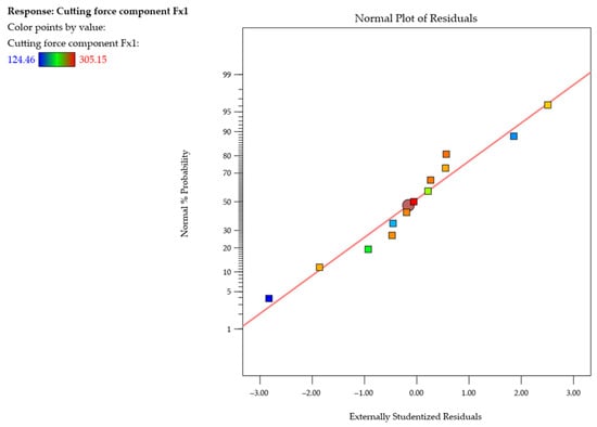
Figure 10.
Normal probability plot of studentized residuals for the cutting force component Fx1 (first pass of the cutting tool).
Figure 11 shows the cutting force component Fx1 during the first pass of the cutting tool as a function of the wall thickness and cutting speed. Results are given via response surface (Figure 11a) and contour (Figure 11b) plots. The results demonstrate a clear upward trend in the value of the cutting force component Fx1 with increasing wall thickness. For the thinnest tested wall (t = 1 mm), the Fx1 value is lowest, while a significant increase in this component value was observed with the use of a higher thickness. This probably results from the higher rigidity of this wall. The relationship between cutting speed and this force component is more complex. For each wall thickness, the values of the cutting force component Fx1 increase with cutting speed until the maximum value is reached at a cutting speed of approximately vc ≈ 700 m/min, followed by a decrease in the value of Fx1 with a further increase in the cutting speed. This is probably related to entering the high-speed cutting range. It is important to note that the transition from conventional machining to high-speed cutting differs depending on the material. However, it should be emphasised that the value of the cutting force component Fx1 at vc = 900 m/min is still higher than at vc = 300 m/min. Furthermore, the shape of the resulting response surface is non-linear. The highest values of the cutting force component Fx1 occurred for a combination of the greatest wall thickness t = 2 mm and a cutting speed of approximately vc ≈ 700 m/min, while the lowest values were obtained for the thinnest wall t = 1 mm and the lowest cutting speed vc = 300 m/min.
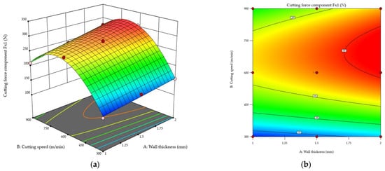
Figure 11.
Cutting force component Fx1 in the first pass of the cutting tool as a function of the wall thickness and cutting speed: (a) response surface plot; (b) contour plot.
After that, the results of the cutting force component Fx2 for the second pass of the end mill were analysed. Again, the maximum values were compared, without taking into account the characteristic extremes resulting from chatter. First, a statistical analysis of the experimental data from the second pass of the cutting tool was performed, and an empirical equation was defined to predict the cutting force component Fx2 as a function of the cutting speed and wall thickness. For this purpose, ANOVA was employed, and its results demonstrated that the quadratic model provided the best fit to the experimental data, yielding the following coefficients of determination:
- R2 = 0.9889;
- Adjusted R2 = 0.9810;
- Predicted R2 = 0.9553.
The high values of these coefficients (close to 1) confirm that the adopted quadratic model adequately describes the relationship between the independent variables and the cutting force component Fx2. Furthermore, the difference between the predicted R2 and adjusted R2 values is less than 0.2. This indicates a good fit between the predictive model and the fitted model. The adequate precision value of 30.9410 confirms the good signal-to-noise ratio. Therefore, an empirical regression model was adopted to describe the cutting force component Fx2 as a function of the cutting speed and wall thickness, expressed by Equation (3) with coded variables:
To determine the reliability of the adopted quadratic response surface model, a statistical verification was carried out. To that end, ANOVA was employed, enabling the assessment of the statistical significance of both the entire model and its individual components. In addition, this analysis also made it possible to determine the degree of fit of the theoretical model to the experimental data. As the model F-value is 124.94, the adopted model was found to be statistically significant. The probability that such a high F-value could occur by chance is only 0.01%. This means that the independent variables under study significantly affect the cutting force component Fx2. An analysis of the p-values showed that most model terms met the significance criterion, i.e., p < 0.05, which indicates that they did affect the cutting force component Fx2. It was found that the cutting speed had a strong influence on the cutting force component Fx2, while the wall thickness is also an important factor, yet its influence is weaker. For the interactions AB and A2, no statistical significance was found. For AB, this indicates that wall thickness and cutting speed do not act synergistically and affect the cutting force component Fx2 rather independently, while for A2, this shows that the effect of wall thickness on the cutting force component Fx2 is primarily linear. For a more complete assessment of the model’s fit to the experimental data, a lack-of-fit analysis was also performed to determine whether the model deviates significantly from the actual data. The obtained lack-of-fit F-value of 0.7006 indicates that the lack of fit is not statistically significant, which means that the model accurately reflects the actual relationships between the variables. Concluding, the developed quadratic response surface model describing the cutting force component Fx2 can be considered statistically reliable. This model can be effectively used to predict the cutting force component Fx2 during the second pass of the cutting tool under similar experimental conditions. Table 7 lists ANOVA results for the response surface quadratic model describing the cutting force component Fx2 during the second pass of the cutting tool.
Table 7.
ANOVA for the response surface quadratic model of the cutting force component Fx2 (second pass of the cutting tool).
Figure 12 shows the normal probability plot of studentized residuals for the cutting force component Fx2 during the second pass of the end mill. On this basis, it was concluded that the residuals follow a straight line, suggesting that the model is adequate. No response transformation was observed, nor were there any significant deviations from the normal distribution (no curvatures, no point clusters, no outliers).
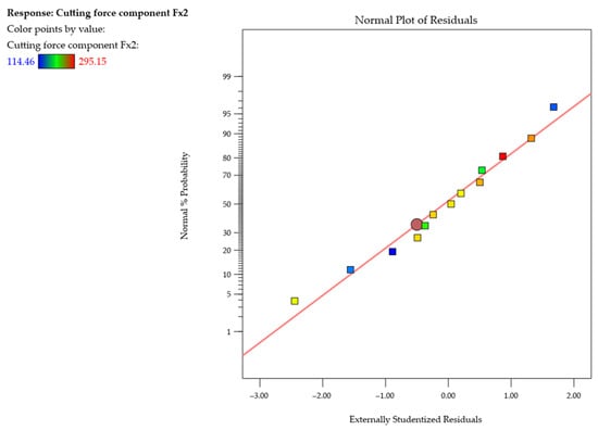
Figure 12.
Normal probability plot of studentized residuals for the cutting force component Fx2 (second pass of the cutting tool).
Relationships between the cutting force component Fx2 during the second pass of the cutting tool and the wall thickness and cutting speed are shown in Figure 13 as response surface (Figure 13a) and contour (Figure 13b) plots, demonstrating that the values of the cutting force component Fx2 increase with wall thickness. The lowest values of the cutting force component Fx2 were observed for a wall thickness of t = 1 mm, while the highest values were obtained for t = 2 mm. The same correlation between cutting speed and the cutting force component Fx2 was observed for each tested wall thickness. A cutting speed increase causes an increase in the cutting force component Fx2 until it reaches the maximum value at a cutting speed of approximately vc ≈ 700 m/min, but a further increase in the cutting speed causes the cutting force component Fx2 to decrease. Importantly, the values of the cutting force component Fx2 at vc = 900 m/min are still higher than those observed at vc = 300 m/min. Concluding, the highest values of the cutting force component Fx2 were obtained for a combination of the thickest wall t = 2 mm and a cutting speed of approximately vc ≈ 700 m/min, while the lowest values were obtained for the thinnest wall t = 1 mm and the lowest cutting speed vc = 300 m/min. Furthermore, it should be emphasised that differences were found between the maximum values of the cutting force components Fx1 and Fx2 in two passes of the cutting tool. During the second pass of the end mill, the cutting force component Fx2 was lower (in relation to Fx1).
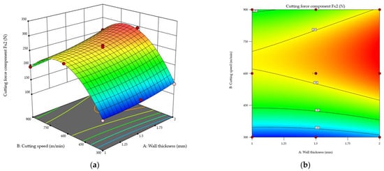
Figure 13.
Cutting force component Fx2 during the second pass of the cutting tool as a function of the wall thickness and cutting speed: (a) response surface plot; (b) contour plot.
The results demonstrate that both independent variables affect the cutting force, specifically the components of this force.
3.2. Cutting Temperature
The final stage of the analysis of the obtained test results involved measuring the cutting temperature T by the natural thermocouple method. Focus was put on the maximum values of electromotive force resulting from a potential difference between two elements of this thermocouple: the workpiece and the cutting tool. Based on a developed reference curve and an equation describing this curve, the corresponding temperatures were determined. This made it possible to convert the electromotive force values into the actual temperature in the contact zone between the cutting tool and the workpiece. Regarding the cutting temperature T, no differences were observed between the first and second passes of the cutting tool; therefore, the maximum temperature values obtained during the machining of both sides of the wall were averaged. It should be noted that the cutting temperature was measured directly at the interface between the cutting edge and the workpiece. Due to the tool geometry and process kinematics, this contact zone can be considered point-like. The cutting temperature was the average of ten maximum peaks observed in the analysed end mill passes. After that, a statistical analysis of the experimental data was performed, and an empirical equation was determined to predict the cutting temperature T as a function of the cutting speed and wall thickness. The ANOVA was used for this purpose, and the results demonstrated the best fit of the quadratic model to the experimental data, which is confirmed by the following coefficients:
- R2 = 0.9911;
- Adjusted R2 = 0.9847;
- Predicted R2 = 0.9812.
The values of the coefficients of determination are close to 1, which confirms that the quadratic model accurately describes the relationship between the cutting speed and wall thickness and the cutting temperature T. Additionally, the difference between the predicted R2 and adjusted R2 values does not exceed 0.2, which indicates a good fit between the predictive model and the fitted model. The adequate precision value of 31.5254 confirms a favourable signal-to-noise ratio, which means that the model is characterised by high prediction quality and stability in terms of the analysed data. On this basis, an empirical regression model was adopted to describe the cutting temperature T as a function of the cutting speed and wall thickness, expressed by Equation (4) using coded variables:
To assess the reliability of the adopted quadratic response surface model, it was verified statistically by ANOVA. The obtained model F-value of 155.98 indicates the model’s statistical significance. The probability of obtaining such a high F-value by chance was estimated at 0.01%, which clearly confirms that the independent variables affect the cutting temperature T. An analysis of the significance levels (p-value) showed that almost half of the components included in the model met the significance criterion (p < 0.05). This means that they have a real impact on variations in the cutting temperature T. Among the factors under consideration, cutting speed has the greatest impact, while wall thickness proved to be a statistically insignificant variable. The interaction components AB and A2 were found to bear no statistical significance either. Additionally, a lack-of-fit analysis was performed. The obtained lack-of-fit F-value of 0.1571 does not indicate significant differences between the predicted and experimental values. This proves that the model accurately reproduces the actual relationships between the analysed process variables. The developed quadratic response surface model can therefore be considered statistically correct and reliable. It is characterised by a good fit to the experimental data and high predictive power, and can thus be effectively used to predict the cutting temperature T under similar experimental conditions. Obtained ANOVA results for the response surface quadratic model describing the cutting temperature T are listed in Table 8.
Table 8.
ANOVA for the response surface quadratic model for the cutting temperature T.
An analysis of the normal probability plot of the studentized residuals for the cutting temperature T shown in Figure 14 reveals that the residuals follow a straight line, which suggests that the model is adequate. In addition to that, the plots show no response transformations or normal distribution problems.
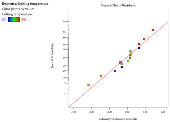
Figure 14.
Normal probability plot of studentized residuals for the cutting temperature T.
Figure 15 shows the pattern of variations in the cutting temperature T as a function of the cutting speed and wall thickness. The analysis was based on response surface (Figure 15a) and contour (Figure 15b) plots. A merely slight increase in the temperature T was observed with increasing the wall thickness, and the ANOVA results confirmed a lack of statistical significance for this variable. It was found that, whatever the wall thickness, the cutting temperature T would increase with increasing the cutting speed up to vc ≈ 700 m/min, while a further raising to vc = 900 m/min would cause a slight decrease in the temperature. The maximum cutting temperature T of about 360 °C was observed for a wall thickness of t = 2 mm and a cutting speed of approximately vc ≈ 700 m/min, while the lowest value of T was obtained for the thinnest wall t = 1 mm and the lowest cutting speed vc = 300 m/min.
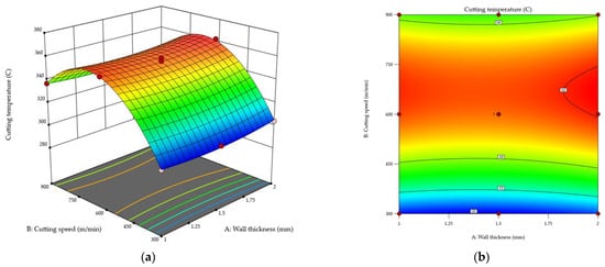
Figure 15.
Cutting temperature T as a function of wall thickness and cutting speed: (a) response surface plot; (b) contour plot.
The results demonstrate that the cutting temperature T primarily depends on the cutting speed.
4. Discussion
An analysis of the results confirms the key role of thermomechanical interactions in thin wall milling at a maximum axial depth of cut, where thermal and mechanical effects occur simultaneously and are intertwined. The cutting force in this process was found to be significantly affected by both wall thickness and cutting speed, while the cutting temperature was primarily dependent on the cutting speed.
The results of the cutting force components showed that the Fx component plays a key role in the identification of mechanical interactions in thin wall milling at a maximum axial depth of cut. The maximum values of the Fx component were lower in the second pass of the tool than in the first pass. Also, during the machining of the other side of the wall, there were significant fluctuations in the amplitude of this component, indicating the instability of the machining process. The fluctuations probably resulted from a reduced rigidity [] of the wall in the second tool pass (due to the removed machining allowance in the first pass). This phenomenon was particularly pronounced for the thinnest tested wall (t = 1 mm), while the highest values of the cutting force component Fx (excluding temporary extremes) were observed for the thickest tested wall t = 2 mm. This was probably related to the fact that as the wall thickness was increased, its susceptibility to elastic-plastic deformation under the cutting force decreased; hence, it can be concluded that the thicker the wall, the higher the observed cutting force value. This effect can be attributed to the low stiffness of thin-walled elements []. The cutting speed was found to have a non-linear impact on the cutting force component Fx. An increase in the value of this component was observed when the cutting speed was increased to approximately ≈ 700 m/min, while a further increase in vc led to its decrease. This phenomenon can be linked to entering the high-speed cutting range, which results from a decrease in the friction factor and a lower share of strains in the total energy balance of the process, leading to a reduced mechanical load [,]. This is due to a shorter heat-exposure time of the tool and the workpiece, predominance of chip heat dissipation, and thermomechanical effects such as adiabatic chip shear []. In addition to that, a close correlation was observed between the cutting force component Fx and the post-machining deformation of a thin wall []. The areas with the highest amplitude of this component corresponded to the locations of local distortions and characteristic vertical marks on the surface. Two such marks were observed for a wall thickness of t = 1 mm and one for a thickness of t = 2 mm (for vc = 300 m/min), which confirms that the process stability increased as the wall thickness was increased.
The cutting temperature T was found to depend mainly on the cutting speed []. An increase in the temperature was observed as the cutting speed was increased to vc ≈ 700 m/min, while a further increase in the cutting speed to vc = 900 m/min resulted in a slight decrease in the temperature value. The maximum temperature T of about 360 °C was observed for a wall thickness of t = 2 mm and a cutting speed of approximately vc ≈ 700 m/min, while the lowest temperature was measured for the thinnest tested wall, t = 1 mm, and the lowest tested cutting speed vc = 300 m/min. The temperature variations were primarily due to increasing friction between the tool, the chip, and the workpiece as the cutting speed was increased []. The temperature decrease observed in the range of vc = 700–900 m/min probably resulted from lower cutting resistance, a phenomenon which is characteristic of high-speed cutting [].
The empirical models developed using the response surface method showed a very good fit to the experimental data (the coefficient of determination R2 > 0.98), which confirms their high predictive reliability. The ANOVA results showed both the wall thickness and cutting speed to be statistically significant for the cutting force component Fx, while for the cutting temperature T, the only statistically significant variable was cutting speed.
Summing up, the results have demonstrated that walls with thicknesses of t ≥ 1.5 can be milled at a maximum axial depth of cut, provided that the cutting speed is selected appropriately and the machining process stability is ensured. The examination of thermomechanical interactions has confirmed their key role in the post-machining deformation of thin walls made of the 7050 T7451 alloy. Thermal and mechanical phenomena occur simultaneously and interact with each other, thus affecting the stability and accuracy of the machining process. Additionally, it should be emphasised that this study is a continuation of the author’s research presented in the work []. A key issue when milling thin-walled components is the prevention of chatter [,] by optimisation of process parameters []. Therefore, further studies should include a modal analysis of the entire system (tool–holder–spindle–workpiece), which allows for the development of stability lobe diagrams showing the stability limits of a milling process as a function of the spindle speed and axial depth of cut (less often, radial depth of cut, i.e., milling width) [,,].
5. Conclusions
The results of this study lead to the following conclusions:
- The study showed that the highest maximum values (excluding characteristic extremes resulting from temporary process instability due to chatter) were obtained for the cutting force component Fx compared to the other two components, Fy and Fz. The Fx component was found to have a decisive impact on the post-machining deformation of thin walls. An analysis of the time curves showed that an increase in the amplitude of this component resulted in wall distortion and the formation of characteristic vertical marks on the machined surface.
- The highest values of Fx were observed at a cutting speed of approximately ≈ 700 m/min, while a further increase in the speed led to a decrease in this force component. This phenomenon can be associated with the transition from conventional machining to high-speed cutting, where friction and plastic stress in the cutting zone are reduced, leading to lower cutting resistance. Despite a partial decrease in Fx at the highest tested speed of vc = 900 m/min, its value remained significantly higher than that observed at vc = 300 m/min.
- For the thinnest tested wall, t = 1 mm, the greatest instability of the machining process and clear signs of chatter were observed, while an increase in the wall thickness to t = 2 mm resulted in enhanced process stability and reduced post-machining deformation. This was due to an increase in the rigidity of the workpiece, which reduced its susceptibility to chatter. At the same time, the results confirmed that in terms of achieving the required dimensional and shape accuracy, the wall thickness value t ≥ 1.5 mm was the minimum for milling at a maximized axial depth of cut.
- Regarding the impact of wall thickness on the cutting force component Fx, the results showed that an increase in the wall thickness value would lead to a higher Fx component. The observed behaviour is probably related to the fact that, as the wall thickness was increased, the stiffness of the workpiece increased too, thereby reducing its susceptibility to elastic-plastic deformation under the cutting force. As a result, the cutting force values vary, since the formation of wall deflection during machining alters the cross-section of the material being removed.
- The cutting temperature T primarily depends on the cutting speed. It was observed that the temperature increased as the cutting speed was increased to vc ≈ 700 m/min, whereas a further increase in the cutting speed to vc = 900 m/min led to a slight decrease in the temperature. The maximum observed temperature T was approximately 360 °C.
- The empirical models developed using response surface methodology showed a very high level of fit (R2 > 0.98). This proves their suitability for predicting the tested variables under similar machining conditions. The ANOVA results demonstrated the statistical significance of both cutting force and wall thickness for the cutting force component Fx, while for the cutting temperature T, it was only cutting speed that was statistically significant.
- The dominant factors inducing the post-machining deformation of thin walls include the interaction between cutting force and heat generated in the cutting zone, as well as the occurrence of chatter. These mechanical and thermal effects are closely related, and their interaction affects the quality of a finished product.
- Thin wall milling at a maximized axial depth of cut is possible but requires ensuring adequate dynamic stability of the tool–holder–spindle system, as well as taking into account the aspect of workpiece rigidity, which is a complex issue in the case of thin-walled structural components. In the future, the modal analysis for the whole system should be performed.
The proposed integrated research approach related to the thermomechanical interaction analysis, including cutting force and cutting temperature, is an effective tool for optimising the machining parameters of thin-walled components, ensuring their dimensional and shape accuracy. The combination of these solutions makes it possible not only to predict process behaviour under industrial conditions, but also to consciously control technological parameters in order to minimise deformation and improve the quality of manufactured components.
Funding
This publication is a result of the project entitled “Development of the milling technique of thin-walled integral elements made of aviation light metal alloys in the context of minimalisation post-machining deformations,” contract number: LIDER14/0153/2023; total project value: 1,543,750.00 PLN. This project is financed by the National Centre for Research and Development under the 14th edition of the LIDER Programme.
Institutional Review Board Statement
Not applicable.
Informed Consent Statement
Not applicable.
Data Availability Statement
The original contributions presented in this study are included in the article. Further inquiries can be directed to the corresponding author.
Conflicts of Interest
The author declares no conflicts of interest.
Appendix A
Table A1.
Experimental design and results of face-centred central composite design (FCCCD).
Table A1.
Experimental design and results of face-centred central composite design (FCCCD).
| Run | Actual Variable 1: Wall Thickness A [mm] | Coded Variable 1: Wall Thickness A [-] | Actual Variable 2: Cutting Speed B [m/min] | Coded Variable 2: Cutting Speed B [-] | Response 1: Cutting Force Component Fx1 [N] | Response 2: Cutting Force Component Fx2 [N] | Response 3: Cutting Temperature T [°C] |
|---|---|---|---|---|---|---|---|
| 1 | 1 | −1 | 300 | −1 | 124.46 | 114.46 | 301 |
| 2 | 1.5 | 0 | 300 | −1 | 149.76 | 129.76 | 301 |
| 3 | 1.5 | 0 | 600 | 0 | 281.52 | 269.48 | 358 |
| 4 | 1 | −1 | 900 | +1 | 210.23 | 196.23 | 337 |
| 5 | 2 | +1 | 600 | 0 | 305.15 | 295.15 | 362 |
| 6 | 1.5 | 0 | 600 | 0 | 279.98 | 256.25 | 359 |
| 7 | 1.5 | 0 | 900 | +1 | 243.26 | 213.26 | 335 |
| 8 | 1 | −1 | 600 | 0 | 269.05 | 249.05 | 358 |
| 9 | 2 | +1 | 300 | −1 | 156.49 | 136.49 | 304 |
| 10 | 1.5 | 0 | 600 | 0 | 274.14 | 264.08 | 356 |
| 11 | 2 | +1 | 900 | +1 | 274.74 | 254.74 | 339 |
| 12 | 1.5 | 0 | 600 | 0 | 284.15 | 258.19 | 352 |
| 13 | 1.5 | 0 | 600 | 0 | 285.79 | 246.19 | 351 |
References
- Kiran, K.; Bediz, B. Predicting Workpiece Dynamics in Milling of Thin-Walled Structures Using Three-Dimensional Spectral Element Method. Thin-Walled Struct. 2025, 217, 113851. [Google Scholar] [CrossRef]
- Bałon, P.; Rejman, E.; Świątoniowski, A.; Kiełbasa, B.; Smusz, R.; Szostak, J.; Cieślik, J.; Kowalski, Ł. Thin-Walled Integral Constructions in Aircraft Industry. Procedia Manuf. 2020, 47, 498–504. [Google Scholar] [CrossRef]
- Wang, J.; Zhang, D.; Wu, B.; Luo, M. Prediction of Distortion Induced by Machining Residual Stresses in Thin-Walled Components. Int. J. Adv. Manuf. Technol. 2018, 95, 4153–4162. [Google Scholar] [CrossRef]
- Lassila, A.A.; Svensson, D.; Wang, W.; Andersson, T. Numerical Evaluation of Cutting Strategies for Thin-Walled Parts. Sci. Rep. 2024, 14, 1459. [Google Scholar] [CrossRef]
- Masoudi, S.; Amini, S.; Saeidi, E.; Eslami-Chalander, H. Effect of Machining-Induced Residual Stress on the Distortion of Thin-Walled Parts. Int. J. Adv. Manuf. Technol. 2015, 76, 597–608. [Google Scholar] [CrossRef]
- Herranz, S.; Campa, F.J.; de Lacalle, L.N.L.; Rivero, A.; Lamikiz, A.; Ukar, E.; Sánchez, J.A.; Bravo, U. The Milling of Airframe Components with Low Rigidity: A General Approach to Avoid Static and Dynamic Problems. Proc. Inst. Mech. Eng. Part B J. Eng. Manuf. 2005, 219, 789–801. [Google Scholar] [CrossRef]
- Soori, M. Deformation Error Compensation in 5-Axis Milling Operations of Turbine Blades. J. Braz. Soc. Mech. Sci. Eng. 2023, 45, 289. [Google Scholar] [CrossRef]
- Czyżycki, J.; Marciniak-Podsadna, L.; Twardowski, P. Classification of Deflections of Thin-Walled Elements Made of EN AW-7075A Aluminum Alloy during Milling. Adv. Sci. Technol. Res. J. 2023, 17, 301–314. [Google Scholar] [CrossRef]
- Kurpiel, S.; Zagórski, K.; Cieślik, J.; Skrzypkowski, K. Investigation of Selected Surface Topography Parameters and Deformation during Milling of Vertical Thin-Walled Structures from Titanium Alloy Ti6Al4V. Materials 2023, 16, 3182. [Google Scholar] [CrossRef]
- Korpysa, J.; Kuczmaszewski, J.; Zagórski, I. Capability Analysis of AZ91D Magnesium Alloy Precision Milling Process with Coated Tools. Materials 2023, 16, 3119. [Google Scholar] [CrossRef]
- Kosicka, E.; Borowiec, M.; Kowalczuk, M.; Krzyzak, A. Dynamic Behavior of Aviation Polymer Composites at Various Weight Fractions of Physical Modifier. Materials 2021, 14, 6897. [Google Scholar] [CrossRef] [PubMed]
- Ciecieląg, K.; Zaleski, K. Milling of Three Types of Thin-Walled Elements Made of Polymer Composite and Titanium and Aluminum Alloys Used in the Aviation Industry. Materials 2022, 15, 5949. [Google Scholar] [CrossRef] [PubMed]
- Fang, Z.; Qian, S.; Wang, C.; Wu, J.; Shen, B. Milling Deformation Prediction for Thin-Walled Components Based on Fusion Model. Int. J. Adv. Manuf. Technol. 2024, 135, 3437–3449. [Google Scholar] [CrossRef]
- Bałon, P.; Rejman, E.; Kiełbasa, B.; Smusz, R. Using HSM Technology in Machining of Thin-Walled Aircraft Structures. Acta Mech. Autom. 2022, 16, 27–33. [Google Scholar] [CrossRef]
- Hussain, A.; Lazoglu, I. Distortion in Milling of Structural Parts. CIRP Ann.-Manuf. Technol. 2019, 68, 105–108. [Google Scholar] [CrossRef]
- Cerutti, X.; Mocellin, K. Influence of the Machining Sequence on the Residual Stress Redistribution and Machining Quality: Analysis and Improvement Using Numerical Simulations. Int. J. Adv. Manuf. Technol. 2016, 83, 489–503. [Google Scholar] [CrossRef]
- Radu, P.; Schnakovszky, C. A Review of Proposed Models for Cutting Force Prediction in Milling Parts with Low Rigidity. Machines 2024, 12, 140. [Google Scholar] [CrossRef]
- Del Sol, I.; Rivero, A.; de Lacalle, L.N.L.; Gamez, A.J. Thin-Wall Machining of Light Alloys: A Review of Models and Industrial Approaches. Materials 2019, 12, 2012. [Google Scholar] [CrossRef]
- Cai, Y.; Zhang, Z.; Xi, X.; Zhao, D. A Deformation Control Method in Thin-Walled Parts Machining Based on Force and Stiffness Matching Via Cutter Orientation Optimization. J. Manuf. Sci. Eng. 2023, 145, 031007. [Google Scholar] [CrossRef]
- Li, C.; Yue, C.; Xu, Y.; Liu, X.; Wang, L.; Hu, D. Simulation Study on Multi-Process Milling Deformation of Frame Thin-Walled Parts Considering Initial Residual Stress. Int. J. Adv. Manuf. Technol. 2025, 136, 5553–5568. [Google Scholar] [CrossRef]
- Wu, G.; Li, G.; Pan, W.; Raja, I.; Wang, X.; Ding, S. A State-of-Art Review on Chatter and Geometric Errors in Thin-Wall Machining Processes. J. Manuf. Process. 2021, 68, 454–480. [Google Scholar] [CrossRef]
- Li, X.; Ni, J.; Liu, X.; Yue, C.; Yang, S.; Ji, X.; Liang, S.Y.; Wang, L. Chatter-Free Milling of Aerospace Thin-Walled Parts. J. Mater. Process. Technol. 2025, 341, 118903. [Google Scholar] [CrossRef]
- Elhendawy, G.A.; El-Taybany, Y. Evaluation of Different Milling Strategies on the Performance of Aluminium Thin-Walled Parts. Int. J. Mach. Mach. Mater. 2024, 26, 85–96. [Google Scholar] [CrossRef]
- Ma, Y.; Zhang, J.; Yu, D.; Feng, P.; Xu, C. Modeling of Machining Distortion for Thin-Walled Components Based on the Internal Stress Field Evolution. Int. J. Adv. Manuf. Technol. 2019, 103, 3597–3612. [Google Scholar] [CrossRef]
- Li, Y.; Liu, C.; Hao, X.; Gao, J.X.; Maropoulos, P.G. Responsive Fixture Design Using Dynamic Product Inspection and Monitoring Technologies for the Precision Machining of Large-Scale Aerospace Parts. CIRP Ann.-Manuf. Technol. 2015, 64, 173–176. [Google Scholar] [CrossRef]
- Barcenas, L.; Ledesma-Orozco, E.; Van-der-Veen, S.; Reveles-Arredondo, F.; Rodríguez-Sánchez, E.A. An Optimization of Part Distortion for a Structural Aircraft Wing Rib: An Industrial Workflow Approach. CIRP J. Manuf. Sci. Technol. 2020, 28, 15–23. [Google Scholar] [CrossRef]
- Wang, J.; Ibaraki, S.; Matsubara, A. A Cutting Sequence Optimization Algorithm to Reduce the Workpiece Deformation in Thin-Wall Machining. Precis. Eng. 2017, 50, 506–514. [Google Scholar] [CrossRef]
- Tunc, L.T.; Gulmez, D.A. Tool Path Strategies for Efficient Milling of Thin-Wall Features. J. Manuf. Mater. Process. 2024, 8, 169. [Google Scholar] [CrossRef]
- Jiang, X.; Lu, W.; Zhang, Z. An Approach for Improving the Machining Efficiency and Quality of Aerospace Curved Thin-Walled Parts during Five-Axis NC Machining. Int. J. Adv. Manuf. Technol. 2018, 97, 2477–2488. [Google Scholar] [CrossRef]
- Bałon, P.; Rejman, E.; Smusz, R.; Szostak, J.; Kiełbasa, B. Implementation of High Speed Machining in Thin-Walled Aircraft Integral Elements. Open Eng. 2018, 8, 162–169. [Google Scholar] [CrossRef]
- Liu, H.; Wang, C.; Li, T.; Bo, Q.; Liu, K.; Wang, Y. Fixturing Technology and System for Thin-Walled Parts Machining: A Review. Front. Mech. Eng. 2022, 17, 55. [Google Scholar] [CrossRef]
- Kyocera SGS Solid Carbide Tools. Available online: https://www.kyocera-sgstool.com/ (accessed on 1 September 2025).
- ISCAR Ltd. Manufacturer of Metalworking Tools. Available online: https://www.iscar.com/en-hq/home (accessed on 1 September 2025).
- Jiang, X.; Wang, Y.; Ding, Z.; Li, H. An Approach to Predict the Distortion of Thin-Walled Parts Affected by Residual Stress during the Milling Process. Int. J. Adv. Manuf. Technol. 2017, 93, 4203–4216. [Google Scholar] [CrossRef]
- Li, B.; Deng, H.; Hui, D.; Hu, Z.; Zhang, W. A Semi-Analytical Model for Predicting the Machining Deformation of Thin-Walled Parts Considering Machining-Induced and Blank Initial Residual Stress. Int. J. Adv. Manuf. Technol. 2020, 110, 139–161. [Google Scholar] [CrossRef]
- Yiyang, Z.; Jian, M.; Gang, L.; Man, Z. A Review on Error Generation and Control in Efficient Precision Machining of Thin-Walled Parts. Int. J. Adv. Manuf. Technol. 2024, 133, 2083–2101. [Google Scholar] [CrossRef]
- Kuczmaszewski, J.; Łogin, W.; Pieśko, P.; Zagórski, I. State of Residual Stresses after the Process of Milling Selected Aluminium Alloys. Adv. Sci. Technol. Res. J. 2018, 12, 63–73. [Google Scholar] [CrossRef]
- Zawada-Michałowska, M.; Pieśko, P.; Mrówka-Nowotnik, G.; Nowotnik, A.; Legutko, S. Effect of the Technological Parameters of Milling on Residual Stress in the Surface Layer of Thin-Walled Plates. Materials 2024, 17, 1193. [Google Scholar] [CrossRef]
- Chen, Z.; Qian, L.; Cui, R.; Liu, J.; Zhang, Q. Machining-Induced Residual Stress Analysis and Multi-Objective Optimization for Milling Process of Mg–Li Alloy. Measurement 2022, 204, 112127. [Google Scholar] [CrossRef]
- Zhang, Z.; Zhang, Z.; Zhang, D.; Luo, M. Milling Distortion Prediction for Thin-Walled Component Based on the Average MIRS in Specimen Machining. Int. J. Adv. Manuf. Technol. 2020, 111, 3379–3392. [Google Scholar] [CrossRef]
- Jiang, X.; Kong, X.; He, S.; Wu, K. Modeling the Superposition of Residual Stresses Induced by Cutting Force and Heat during the Milling of Thin-Walled Parts. J. Manuf. Process. 2021, 68, 356–370. [Google Scholar] [CrossRef]
- Ma, Y.; Feng, P.; Zhang, J.; Wu, Z.; Yu, D. Prediction of Surface Residual Stress after End Milling Based on Cutting Force and Temperature. J. Mater. Process. Technol. 2016, 235, 41–48. [Google Scholar] [CrossRef]
- Weber, D.; Kirsch, B.; Chighizola, C.R.; D’Elia, C.R.; Linke, B.S.; Hill, M.R.; Aurich, J.C. Analysis of Machining-Induced Residual Stresses of Milled Aluminum Workpieces, Their Repeatability, and Their Resulting Distortion. Int. J. Adv. Manuf. Technol. 2021, 115, 1089–1110. [Google Scholar] [CrossRef]
- Li, J.; Wang, S. Distortion Caused by Residual Stresses in Machining Aeronautical Aluminum Alloy Parts: Recent Advances. Int. J. Adv. Manuf. Technol. 2017, 89, 997–1012. [Google Scholar] [CrossRef]
- Cerutti, X.; Mocellin, K. Parallel Finite Element Tool to Predict Distortion Induced by Initial Residual Stresses during Machining of Aeronautical Parts. Int. J. Mater. Form. 2015, 8, 255–268. [Google Scholar] [CrossRef]
- Akhtar, W.; Lazoglu, I.; Liang, S.Y. Prediction and Control of Residual Stress-Based Distortions in the Machining of Aerospace Parts: A Review. J. Manuf. Process. 2022, 76, 106–122. [Google Scholar] [CrossRef]
- Navarro-Devia, J.H.; Chen, Y.; Dao, D.V.; Li, H. Chatter Detection in Milling Processes—A Review on Signal Processing and Condition Classification. Int. J. Adv. Manuf. Technol. 2023, 125, 3943–3980. [Google Scholar] [CrossRef]
- Niu, J.; Jia, J.; Wang, R.; Xu, J.; Sun, Y.; Guo, D. State Dependent Regenerative Stability and Surface Location Error in Peripheral Milling of Thin-Walled Parts. Int. J. Mech. Sci. 2021, 196, 106294. [Google Scholar] [CrossRef]
- Li, Z.; Zeng, Z.; Yang, Y.; Ouyang, Z.; Ding, P.; Sun, J.; Zhu, S. Research Progress in Machining Technology of Aerospace Thin-Walled Components. J. Manuf. Process. 2024, 119, 463–482. [Google Scholar] [CrossRef]
- Wang, X.; Zhao, B.; Ding, W.; Pu, C.; Wang, X.; Peng, S.; Ma, F. A Short Review on Machining Deformation Control of Aero-engine Thin-walled Casings. Int. J. Adv. Manuf. Technol. 2022, 121, 2971–2985. [Google Scholar] [CrossRef]
- Sun, Y.; Jiang, S. Predictive Modeling of Chatter Stability Considering Force-Induced Deformation Effect in Milling Thin-Walled Parts. Int. J. Mach. Tools Manuf. 2018, 135, 38–52. [Google Scholar] [CrossRef]
- Bachrathy, D.; Kiss, A.K.; Kossa, A.; Berezvai, S.; Hajdu, D.; Stepan, G. In-Process Monitoring of Changing Dynamics of a Thin-Walled Component during Milling Operation by Ball Shooter Excitation. J. Manuf. Mater. Process. 2020, 4, 78. [Google Scholar] [CrossRef]
- Zawada-Michałowska, M. Thin Wall Milling at a Maximized Axial Depth of Cut. Materials 2025, 18, 5219. [Google Scholar] [CrossRef]
- Antony, J. Design of Experiments for Engineers and Scientists, 2nd ed.; Elsevier: London, UK, 2014; ISBN 9780080994178. [Google Scholar]
- Myers, R.H.; Montgomery, D.C.; Anderson-Cook, C.M. Response Surface Methodology: Process and Product Optimization Using Designed Experiments, 4th ed.; John Wiley & Sons: London, UK, 2016; ISBN 978-1-118-91601-8. [Google Scholar]
- Chen, H.Y.; Chen, C. A Study of the Response Surface Methodology Model with Regression Analysis in Three Fields of Engineering. Appl. Syst. Innov. 2025, 8, 99. [Google Scholar] [CrossRef]
- Veza, I.; Spraggon, M.; Fattah, I.M.R.; Idris, M. Response Surface Methodology (RSM) for Optimizing Engine Performance and Emissions Fueled with Biofuel: Review of RSM for Sustainability Energy Transition. Results Eng. 2023, 18, 101213. [Google Scholar] [CrossRef]
- AMAG ROLLING. Manufacturer’s Inspection Certificate of 7050 T7451, Nr 89320442; AMAG ROLLING: Ranshofen, Austria, 2024. [Google Scholar]
- Si-meng, L.; Xiao-dong, S.; Xiao-bo, G.; Dou, W. Simulation of the Deformation Caused by the Machining Cutting Force on Thin-Walled Deep Cavity Parts. Int. J. Adv. Manuf. Technol. 2017, 92, 3503–3517. [Google Scholar] [CrossRef]
- Hashmi, K.H.; Zakria, G.; Raza, M.B.; Khalil, S. Optimization of Process Parameters for High Speed Machining of Ti-6Al-4V Using Response Surface Methodology. Int. J. Adv. Manuf. Technol. 2016, 85, 1847–1856. [Google Scholar] [CrossRef]
- Zawada-Michałowska, M. High-Performance Milling Techniques of Thin-Walled Elements. Adv. Sci. Technol. Res. J. 2022, 16, 98–110. [Google Scholar] [CrossRef]
- Li, W.; Wang, L.; Yu, G. Force-Induced Deformation Prediction and Flexible Error Compensation Strategy in Flank Milling of Thin-Walled Parts. J. Mater. Process. Technol. 2021, 297, 117258. [Google Scholar] [CrossRef]
- Cheng, M.; Jiao, L.; Yan, P.; Feng, L.; Qiu, T.; Wang, X.; Zhang, B. Prediction of Surface Residual Stress in End Milling with Gaussian Process Regression. Meas. J. Int. Meas. Confed. 2021, 178, 109333. [Google Scholar] [CrossRef]
- Kuczmaszewski, J.; Zagórski, I.; Zgórniak, P. Chip Temperature Measurement in the Cutting Area During Rough Milling Magnesium Alloys with a Kordell Geometry End Mill. Adv. Sci. Technol. Res. J. 2022, 16, 109–119. [Google Scholar] [CrossRef]
- Ankit, J.; Bajpai, V. Chapter 1—Introduction to High-Speed Machining (HSM). In High Speed Machining; Gupta, K., Davim, J.P., Eds.; Academic Press: Cambridge, MA, USA, 2020; pp. 1–25. [Google Scholar]
- Feng, J.; Hou, N.; Jian, Z.; Sun, Z.; Zhang, J. An Efficient Method to Predict the Chatter Stability of Titanium Alloy Thin-Walled Workpieces during High-Speed Milling by Considering Varying Dynamic Parameters. Int. J. Adv. Manuf. Technol. 2020, 106, 5407–5420. [Google Scholar] [CrossRef]
- Zhang, X.-J.; Xiong, C.-H.; Ding, Y.; Zhang, X.-M. Stability Analysis in Milling of Thin-Walled Workpieces with Emphasis on the Structural Effect. Proc. Inst. Mech. Eng. Part B J. Eng. Manuf. 2009, 224, 589–608. [Google Scholar] [CrossRef]
- Wan, M.; Feng, J.; Ma, Y.; Zhang, W. Identification of Milling Process Damping Using Operational Modal Analysis. Int. J. Mach. Tools Manuf. 2017, 122, 120–131. [Google Scholar] [CrossRef]
- Zawada-Michałowska, M.; Pieśko, P.; Józwik, J.; Legutko, S.; Kukiełka, L. A Comparison of the Geometrical Accuracy of Thin-Walled Elements Made of Different Aluminum Alloys. Materials 2021, 14, 7242. [Google Scholar] [CrossRef]
- Weremczuk, A.; Borowiec, M.; Rudzik, M.; Rusinek, R. Stable and Unstable Milling Process for Nickel Superalloy as Observed by Recurrence Plots and Multiscale Entropy. Eksploat. i Niezawodn.–Maint. Reliab. 2018, 20, 318–326. [Google Scholar] [CrossRef]
Disclaimer/Publisher’s Note: The statements, opinions and data contained in all publications are solely those of the individual author(s) and contributor(s) and not of MDPI and/or the editor(s). MDPI and/or the editor(s) disclaim responsibility for any injury to people or property resulting from any ideas, methods, instructions or products referred to in the content. |
© 2025 by the author. Licensee MDPI, Basel, Switzerland. This article is an open access article distributed under the terms and conditions of the Creative Commons Attribution (CC BY) license (https://creativecommons.org/licenses/by/4.0/).