
Fracture and Damage Evolution of Multiple-Fractured Rock-like Material Subjected to Compression

Abstract
:1. Introduction
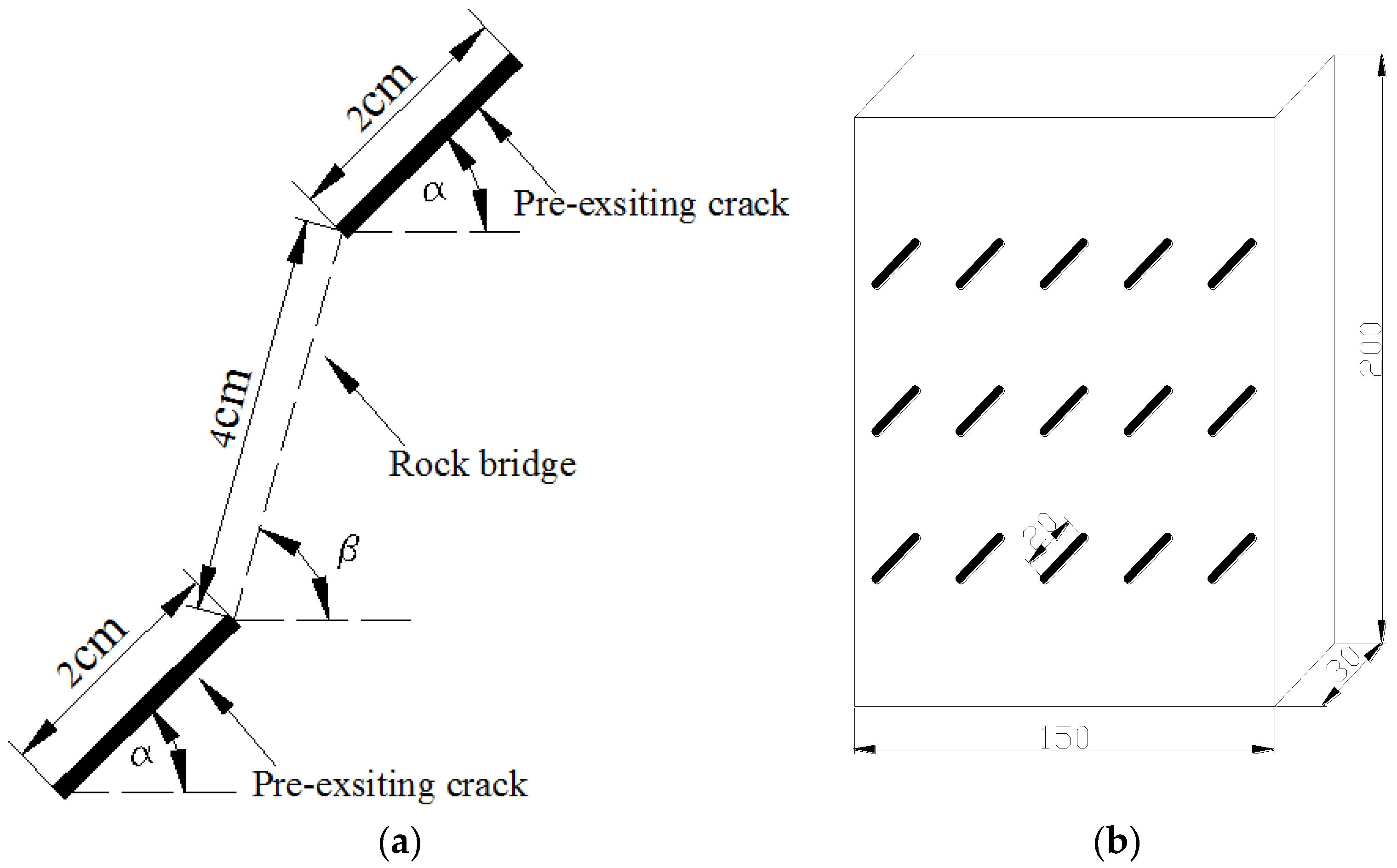
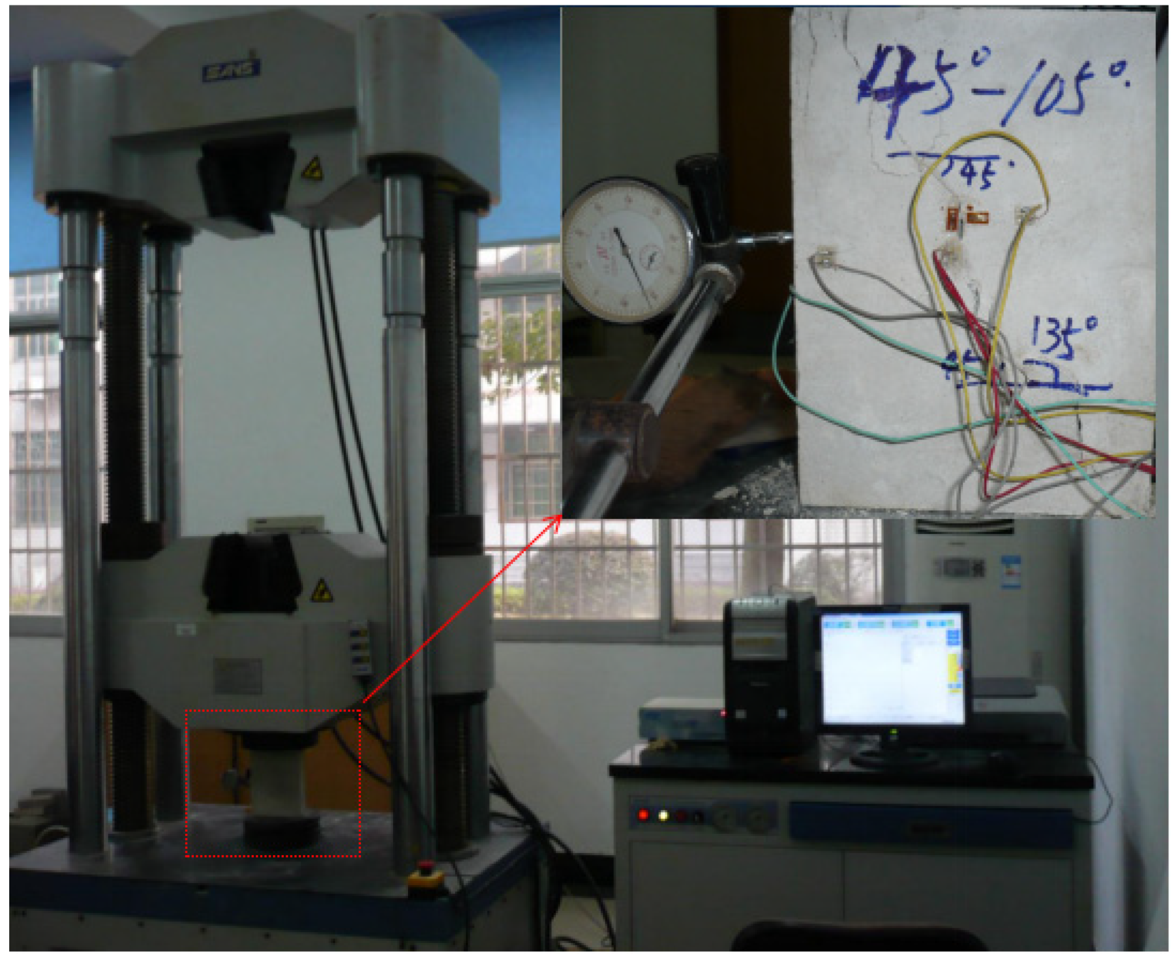
2. Experimental Scheme
3. Multiple-Cracks Failure Mode
3.1. Crack Coalescence Mode
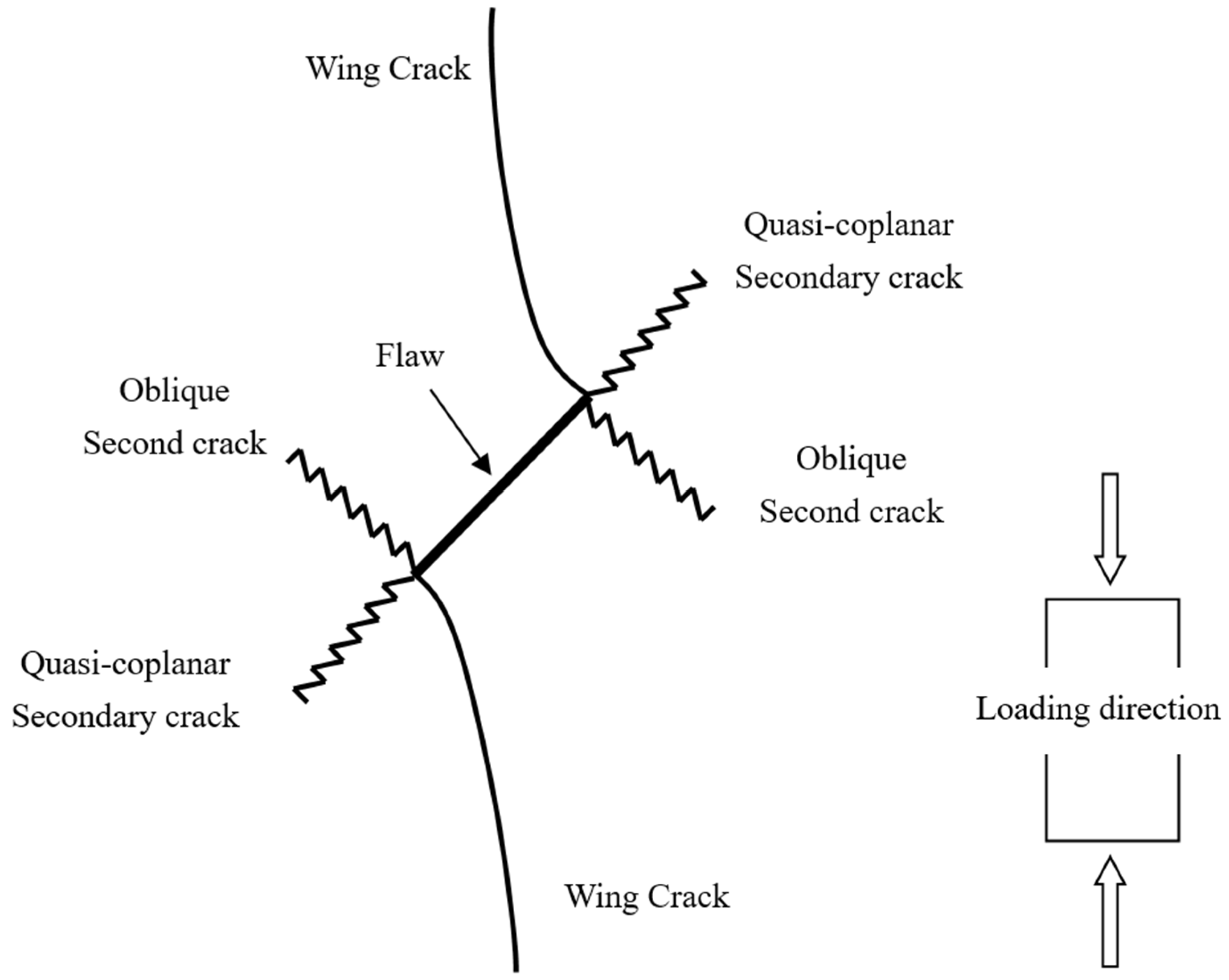
3.2. Multiple-Crack Propagation
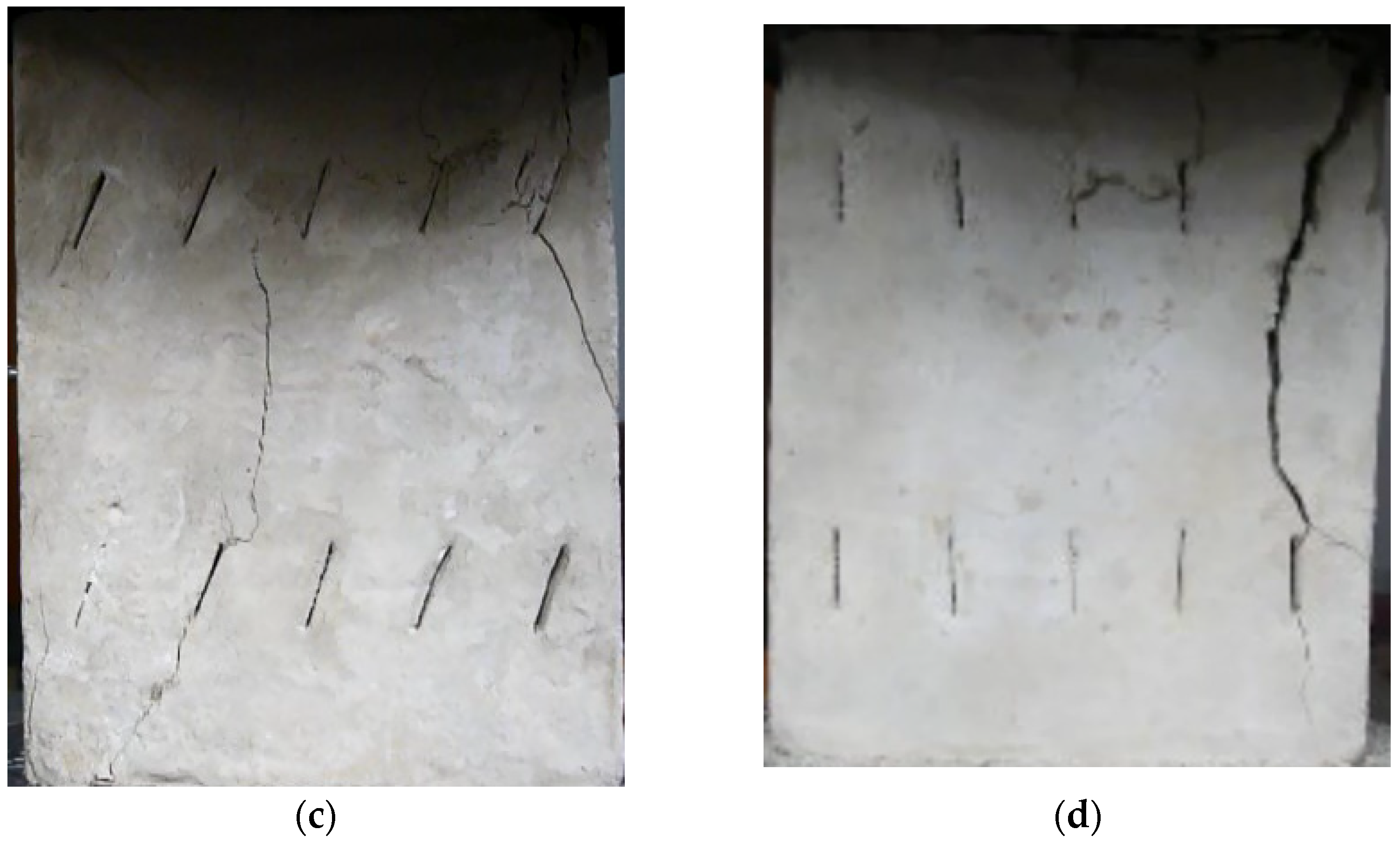
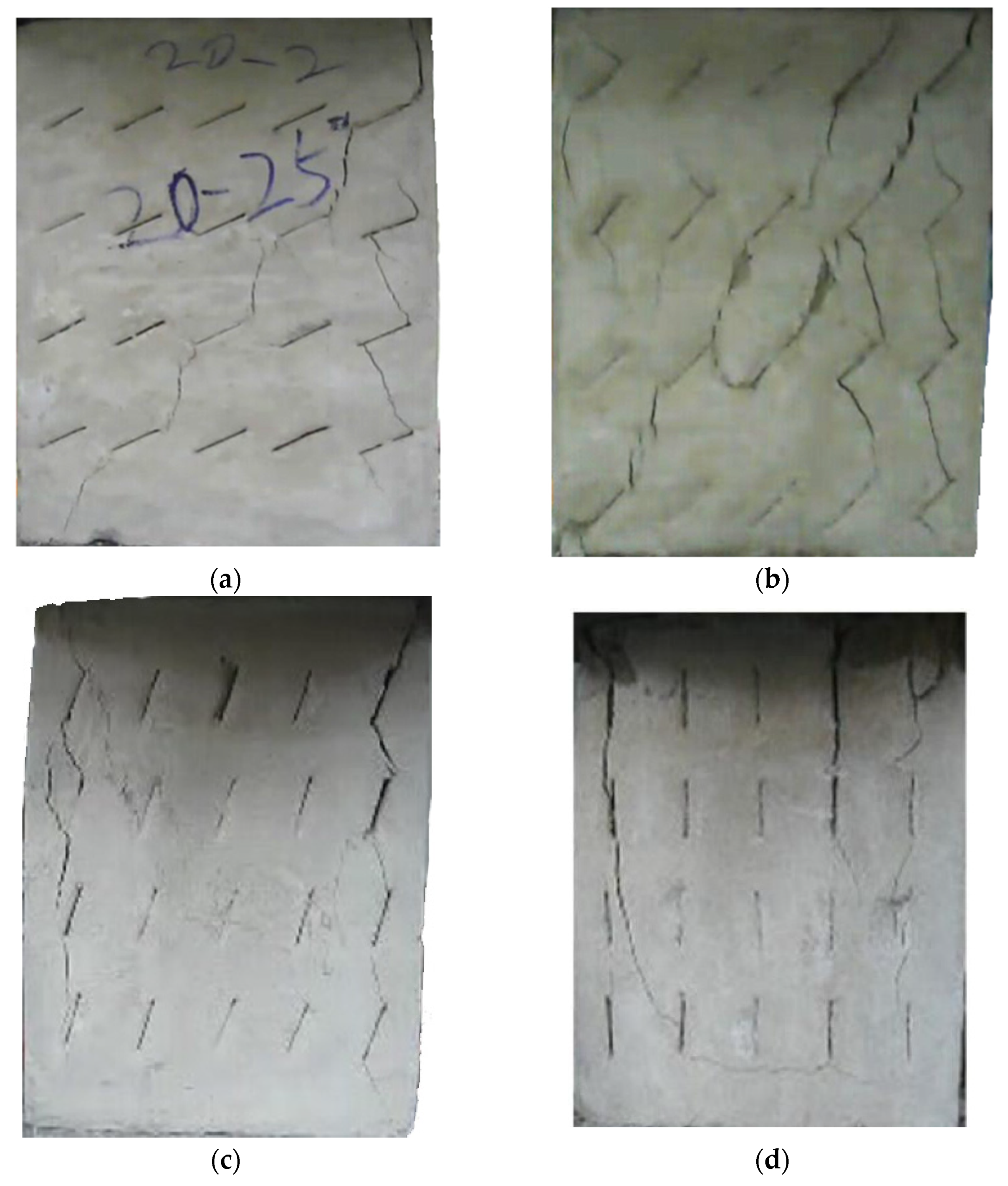
3.3. Multiple-Crack Failure Mode
- (1)
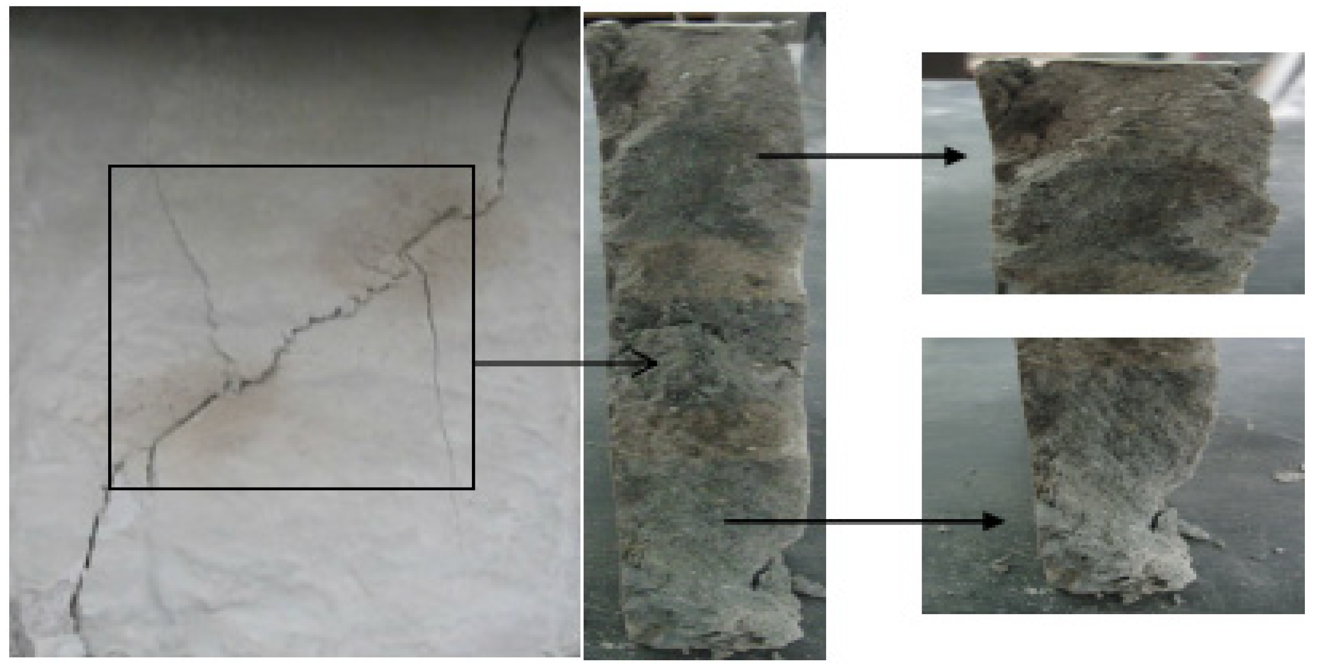
- Wing crack tension failure mode. The main feature of this mode is that the wing cracks initiate and propagate from the pre-existing crack tips at any particular row towards the crack tips in the same rows. Even though both tensile and shear wing cracks existed, the majority belonged to tensile failures.
- (2)
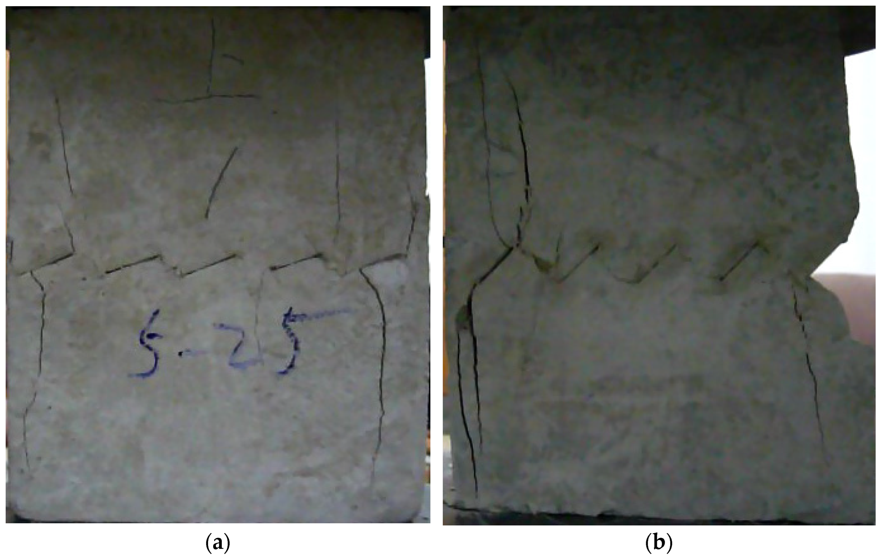
- Second crack shear failure mode. The main feature is that the second shear cracks initiate and propagate from the pre-existing crack tips towards the adjacent row. Again, even though there are both tensile and shear cracks, the majority belong to shear failure.
- (3)
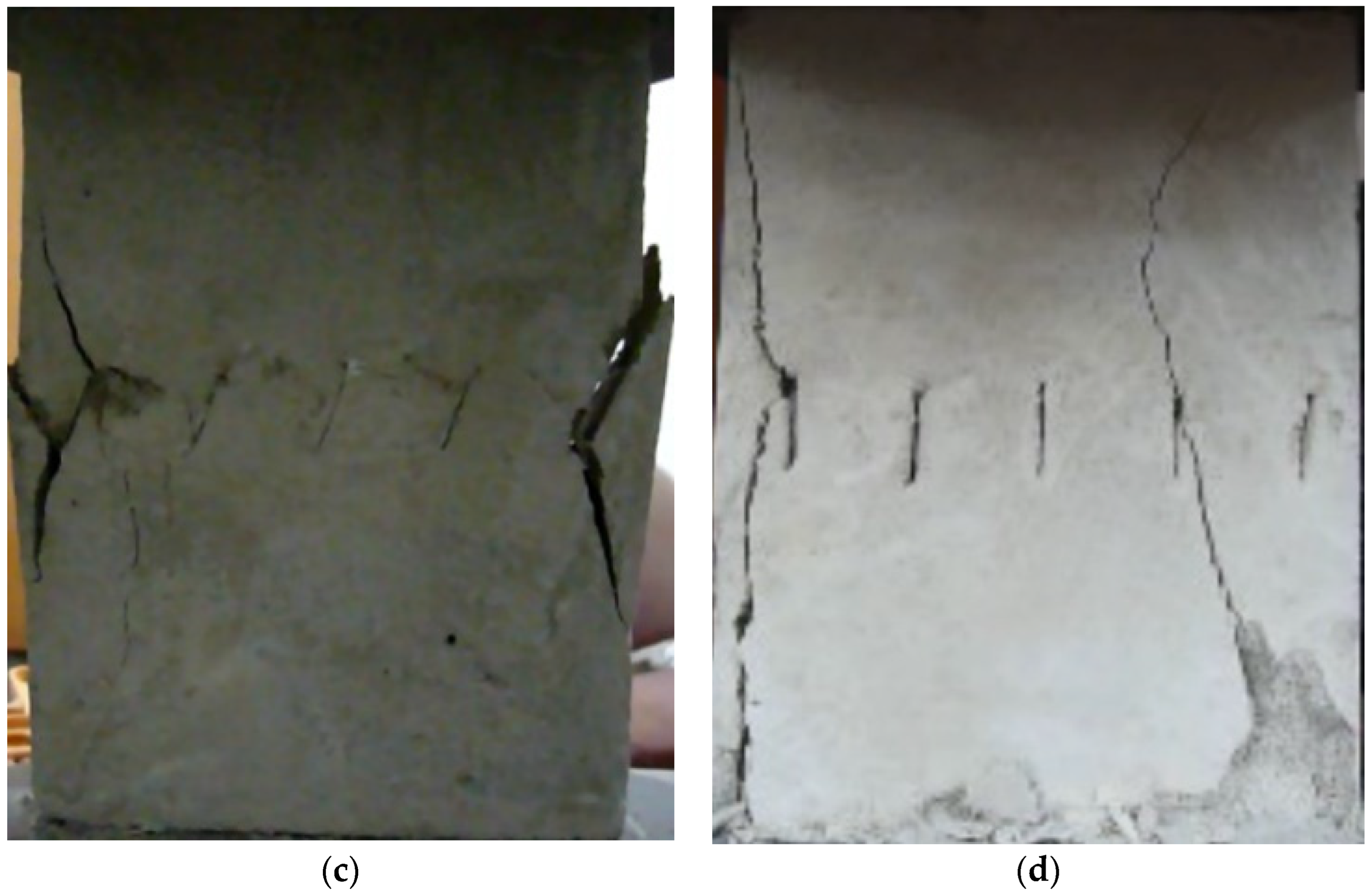
- Stepped path failure mode. The main feature is that there are second cracks initiating from the pre-existing crack tips, and subsequently, tension cracks initiate and propagate from the second cracks towards the adjacent row; the combination of these crack results in several “stepped coalescence patterns”, formed on the failure plane.
- (4)
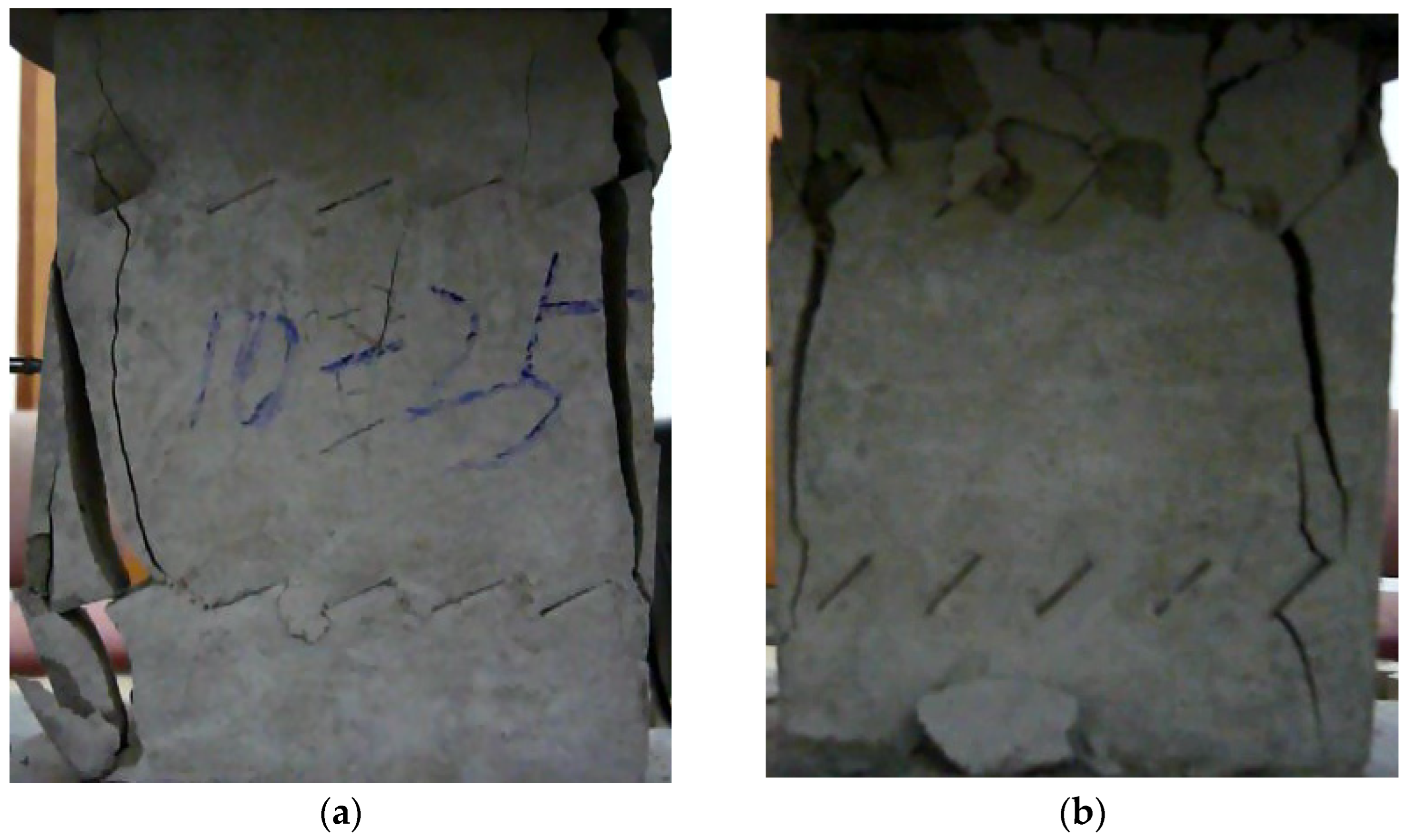
- Intact failure mode. The main feature is that the cracks initiate and propagate in the intact material, between or along the cracks. This failure mode usually occurs when the crack angle is 90° and is similar to the failure pattern of the intact specimens.
4. Deformation and Strength
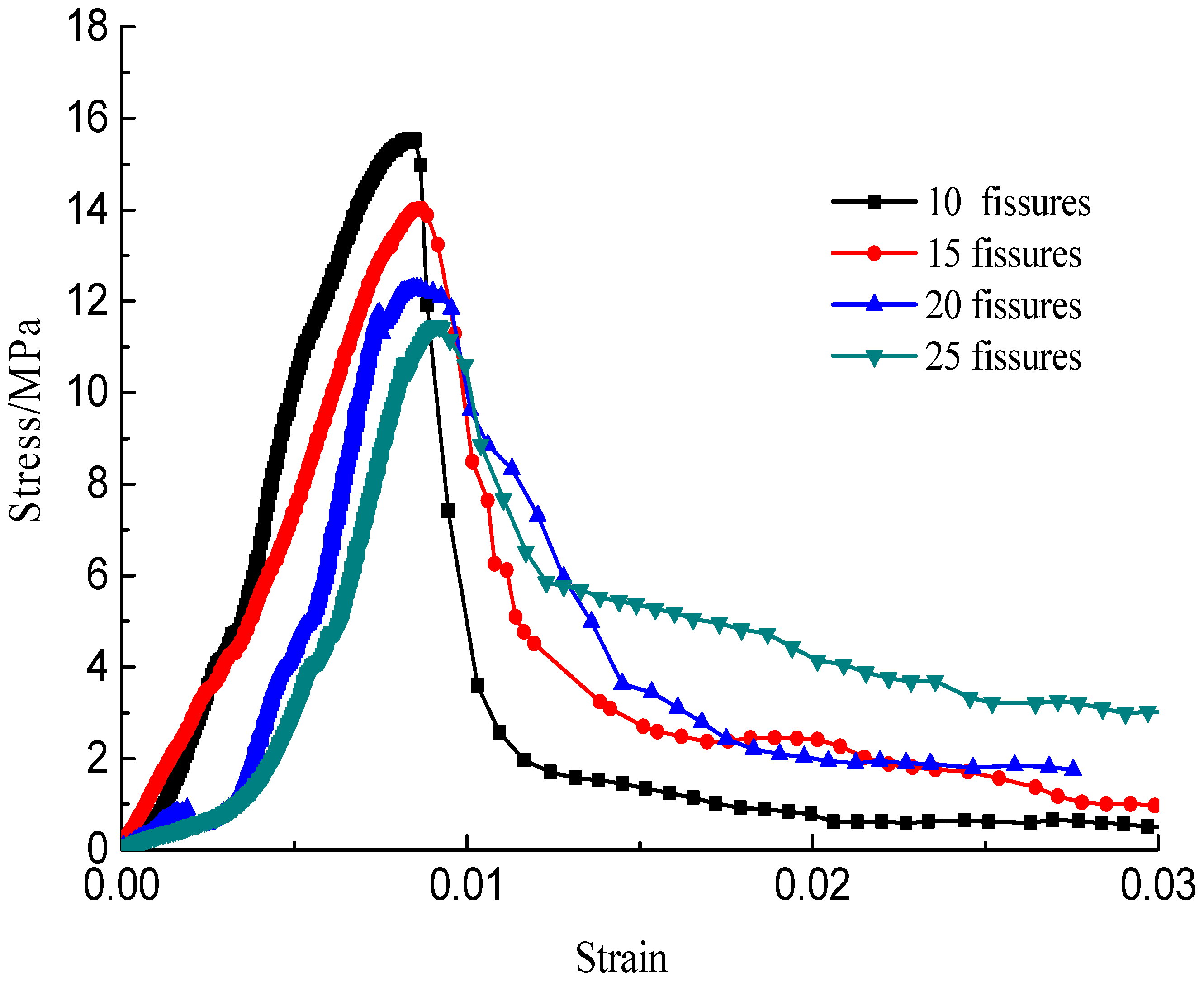
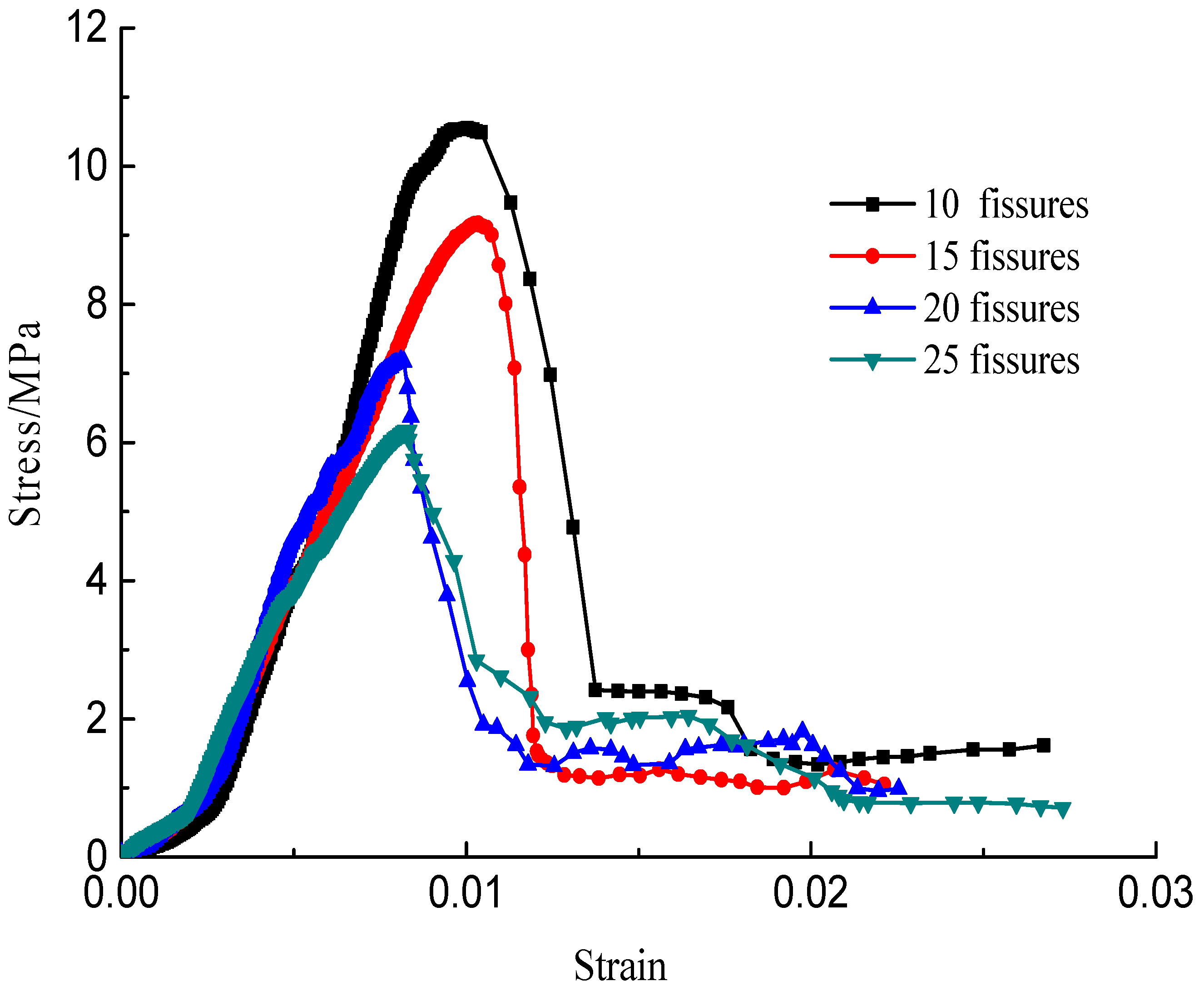
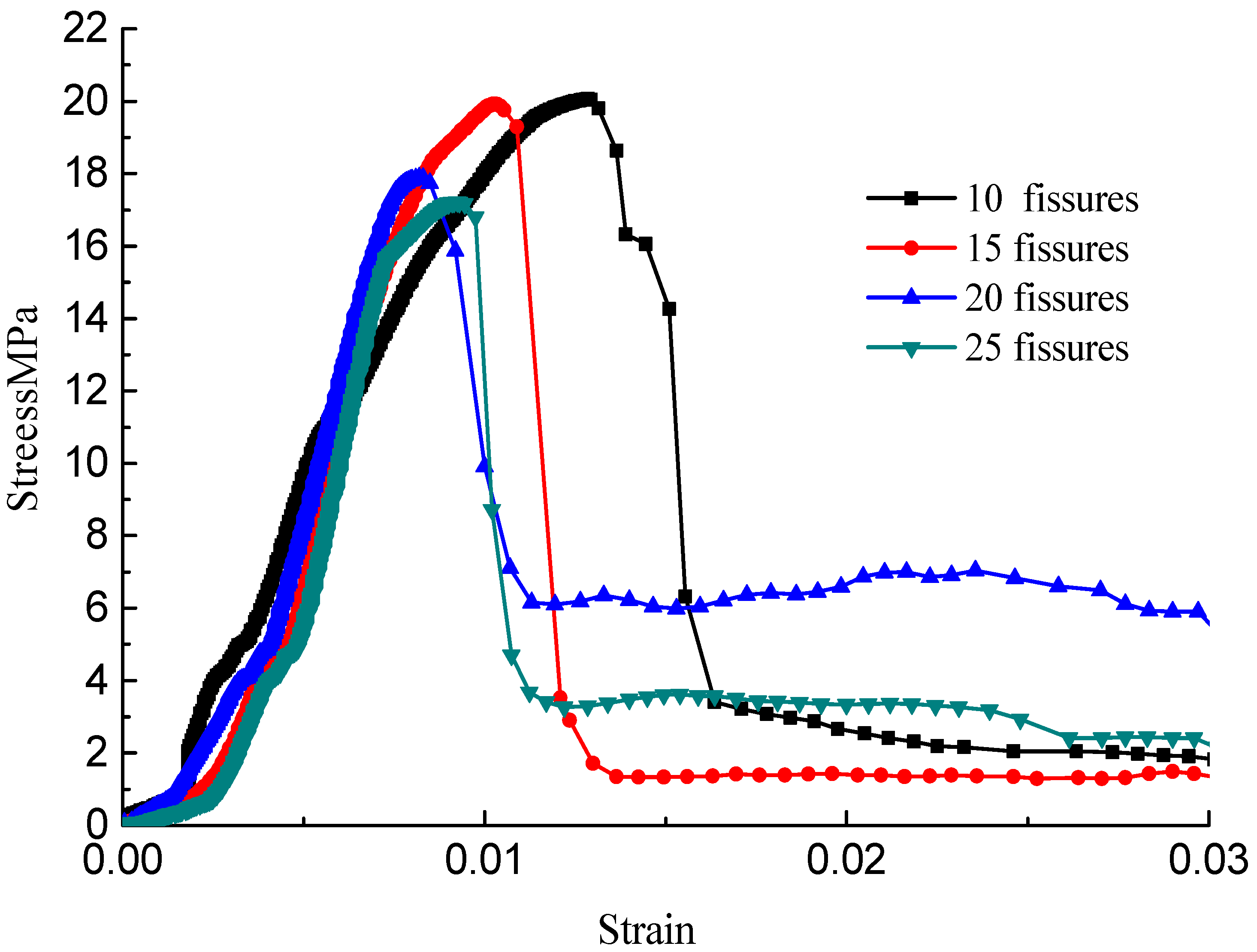
4.1. Stress–Strain Curves
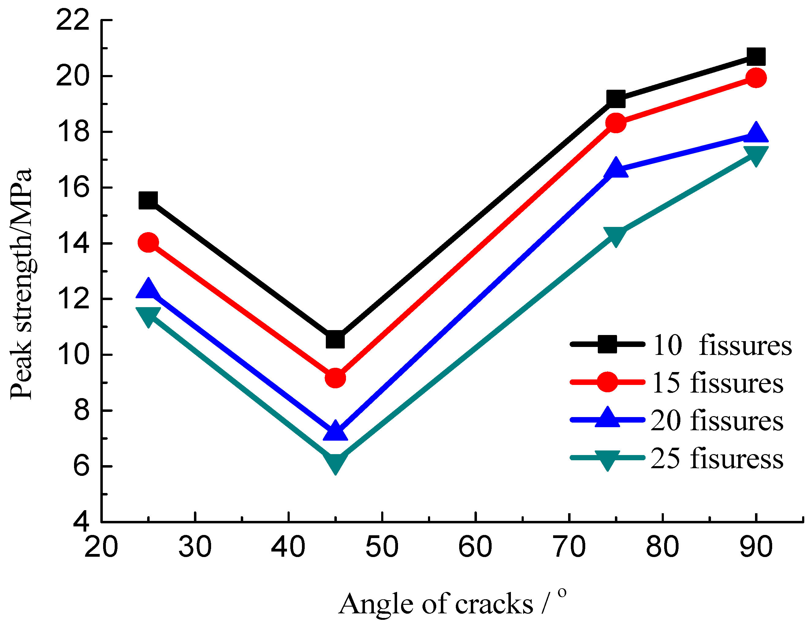
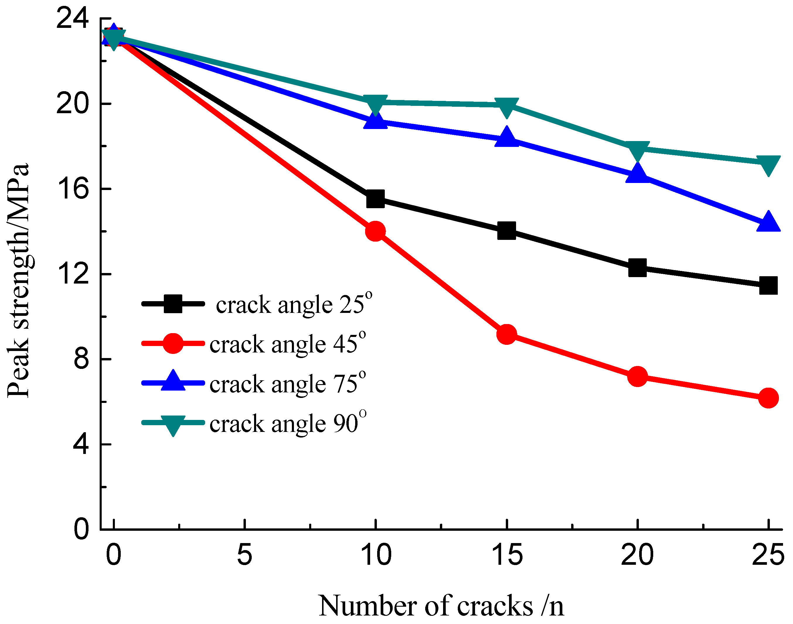
4.2. Strength Characteristics
5. Multi-Crack Damage Fracture Modes
5.1. Crack Initiation
5.2. Wing Crack Propagation
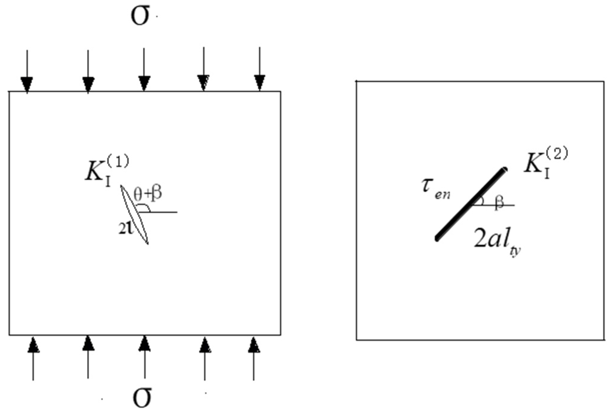
5.3. The Multi-Crack Interaction Models
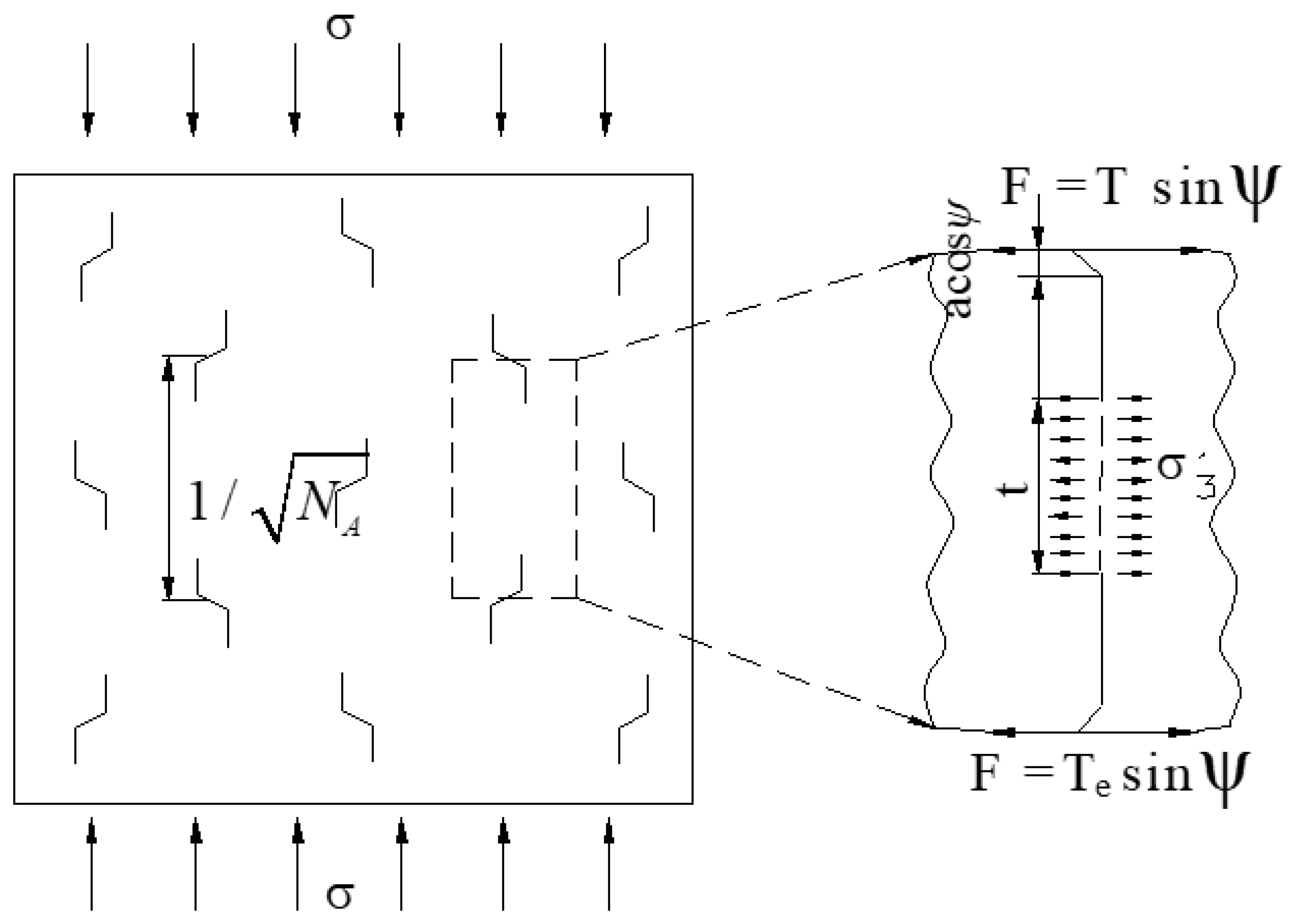
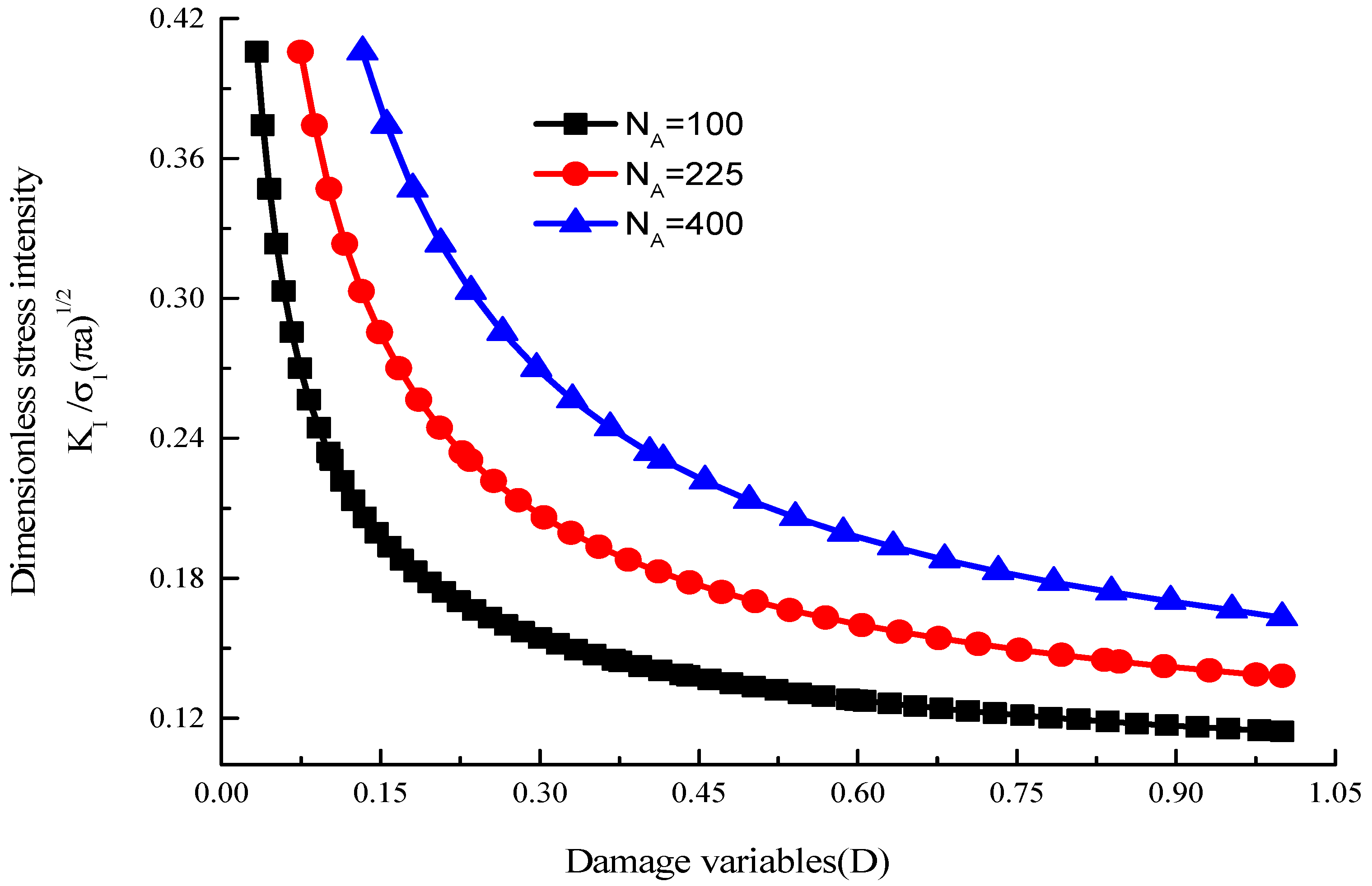
5.4. Multi-Crack Damage Models
6. Conclusions
- (1)
- Compression experiments were conducted for brittle rock-like samples with multiple fissures to explore the failure rules of the rock-like material with different fissure inclination angles and density distributions. Owing to the differences in crack geometries, seven coalescence modes were identified and the failure process of the multiple-fractured specimens was divided into four categories. It was also found that the strength of the multiple-fractured specimens was affected by the crack angle and crack number, and the crack angle was the main influencing factor. The crack density merely affected the transfixion pattern, and the peak value decreased with the increase in the crack number.
- (2)
- Based on the rock fracture mechanics theory, a wing crack propagation model considering the interaction of multiple cracks was established, for the first time, in this study. The multi-crack effect would result in “reinforcement” of the wing crack’s propagation. The multiple-crack initiation criterion was further developed to predict the propagation process of the fractures in the rock mass, which provided a theoretical basis for applications in rock engineering. Comparisons between theory and experiment results indicated that the peak strength of specimens with multiple cracks decreased initially and increased with the increasing inclination angle of the fissures, but the peak strength decreased with the increasing fissure distribution density. This work provides a basis for quantitative research on fractured rock-mass failure subjected to compression.
Author Contributions
Funding
Institutional Review Board Statement
Informed Consent Statement
Data Availability Statement
Conflicts of Interest
References
- Naser Al-Shayea, A. Crack propagation trajectories for rocks under mixed mode I-II fracture. Eng. Geology. 2005, 81, 84–97. [Google Scholar] [CrossRef]
- Li, J.; Huang, Q.; Ren, X. Dynamic Initiation and Propagation of Multiple Cracks in Brittle Materials. Materials 2013, 6, 3241–3253. [Google Scholar] [CrossRef]
- Nicksiar, M.; Martin, C.D. Factors Affecting Crack Initiation in Low Porosity Crystalline Rocks. Rock Mech. Rock Eng. 2014, 47, 1165–1181. [Google Scholar] [CrossRef]
- Xu, J.; Li, Z. Crack Propagation and Coalescence of Step-Path Failure in Rocks. Rock Mech. Rock Eng. 2019, 52, 965–979. [Google Scholar] [CrossRef]
- Shen, Q.Q.; Rao, Q.H.; Li, Z.; Yi, W.; Sun, D.-L. Interacting mechanism and initiation prediction of multiple cracks. Trans. Nonferrous Metals Soc. China 2021, 31, 79–791. [Google Scholar] [CrossRef]
- Pu, C.; Cao, P. Failure characteristics and its influencing factors of rock-like material with multi-cracks under uniaxial compression. Trans. Nonferrous Met. Soc. China 2012, 22, 185–191. [Google Scholar] [CrossRef]
- Wang, M.; Wan, W.; Zhao, Y. Experimental study on crack propagation and the coalescence of rock-like materials with two preexisting fissures under biaxial compression. Bull. Eng. Geol. Environ. 2020, 79, 3121–3144. [Google Scholar] [CrossRef]
- Liu, G.; Chen, Y.; Du, X.; Wang, S.; Fernández-Steeger, T.M. Evolutionary Analysis of Heterogeneous Granite Microcracks Based on Digital Image Processing in Grain-Block Model. Materials 2022, 15, 1941. [Google Scholar] [CrossRef]
- Niu, Y.; Zhou, X.P.; Zhou, L.S. Fracture damage prediction in fissured red sandstone under uniaxial compression: Acoustic emission b-value analysis. Fatigue Fract. Eng. Mater. Struct. 2020, 43, 175–190. [Google Scholar] [CrossRef]
- Gao, Y.; Liu, Z.; Zeng, Q.; Wang, T.; Zhuang, Z.; Hwang, K.C. Theoretical and numerical prediction of crack path in the material with anisotropic fracture toughness. Eng. Fract. Mech. 2017, 180, 330–347. [Google Scholar] [CrossRef]
- Cao, P.; Li, J.; Yuan, H. Testing study of subcritical crack growth rate and fracture toughness in different rocks. Trans. Nonferrous Met. Soc. China 2006, 16, 709–713. [Google Scholar] [CrossRef]
- Park, C.H.; Bobet, A. Crack initiation, propagation and coalescence from frictional flaws in uniaxial compression. Eng. Fract. Mech. 2010, 77, 2727–2748. [Google Scholar] [CrossRef]
- Zhang, X.P.; Wong, L.N.Y. Cracking processes in rock-like material containing a single flaw under uniaxial compression: A numerical study based on parallel bonded-particle model approach. Rock Mech. Rock Eng. 2012, 45, 711–737. [Google Scholar] [CrossRef]
- Li, B.; Yu, S.; Zhu, W.; Cai, W.; Yang, L.; Xue, Y.; Li, Y. The Microscopic Mechanism of Crack Evolution in Brittle Material Containing 3-D Embedded Flaw. Rock Mech. Rock Eng. 2020, 53, 5239–5255. [Google Scholar] [CrossRef]
- Wang, H.; Gao, Y.; Zhou, Y. Experimental and numerical studies of brittle rock-like specimens with unfilled cross fissures under uniaxial compression. Theor. Appl. Fract. Mech. 2022, 117, 103167. [Google Scholar] [CrossRef]
- Lam, K.Y.; Phua, S.P. Multiple crack interaction and its effect on stress intensity factor. Eng Fract Mech. 1991, 40, 585–592. [Google Scholar] [CrossRef]
- Yang, H.; Cao, P.; Xu, W. Mechanism study on subcritical crack growth of flabby and intricate ore rock. Trans. Nonferrous Met. Soc. China 2006, 16, 723–727. [Google Scholar]
- Pu, C.Z. Experiment Research on the Fracture Failure Mechanism of Rock-Like Material with Cracks under Uniaxial Compression; Central South University: Changsha, China, 2010. [Google Scholar]
- Li, Y.; Zhou, H.; Zhu, W.; Li, S.; Liu, J. Numerical Study on Crack Propagation in Brittle Jointed Rock Mass Influenced by Fracture Water Pressure. Materials 2015, 8, 3364–3376. [Google Scholar] [CrossRef] [Green Version]
- Zhang, J.Z.; Zhou, X.P.; Zhou, L.S.; Berto, F. Progressive failure of brittle rocks with non-isometric flaws: Insights from acousto-optic-mechanical (AOM) data. Fatigue Fract. Eng. Mater. Struct. 2019, 42, 1787–1802. [Google Scholar] [CrossRef]
- Dyskin, E.; Sahouryeh, R.J.J. Influence of shape and locations of initial 3-D cracks on their growth in uniaxial compression. Eng. Fract. Mech. 2003, 70, 2115–2136. [Google Scholar] [CrossRef]
- Yang, S.; Jing, H.W.; Wang, S.Y. Experimental Investigation on the Strength, Deformability, Failure Behavior and Acoustic Emission Locations of Red Sandstone Under Triaxial Compression. Rock Mech Rock Eng. 2012, 45, 583–606. [Google Scholar] [CrossRef]
- Liu, G.; Chen, Y.; Du, X.; Xiao, P.; Liao, S.; Azzam, R. Investigation of Microcrack Propagation and Energy Evolution in Brittle Rocks Based on the Voronoi Model. Materials 2021, 14, 2108. [Google Scholar] [CrossRef]
- Ju, M.; Xing, H. Crack propagation in jointed rock and its effect on rock macrofracture resistance: Insights from discrete element analysis. Geomech. Geophys. Geo-Energy Geo-Resour. 2022, 8, 21. [Google Scholar] [CrossRef]
- Mei, J.; Yang, L.; Sheng, X.C.; Ma, X.J.; Sui, B.; Yang, W.M. An experimental and theoretical investigation of time dependent cracking and creep behavior of rocks under triaxial hydro-mechanical coupling. Theor. Appl. Fract. Mech. 2021, 115, 103046. [Google Scholar] [CrossRef]
- Park, C.H.; Bobet, A. Crack coalescence in specimens with open and closed flaws: A comparison. Int. J. Rock Mech. Min. Sci. 2009, 46, 819–829. [Google Scholar] [CrossRef]
- Cao, P.; Liu, T.; Pu, C.Z. Crack propagation and coalescence of brittle rock-like specimens with pre-existing cracks in compression. Eng. Geol. 2015, 187, 113–121. [Google Scholar] [CrossRef]
- Guo, S.; Qi, S.; Zou, Y.; Zheng, B. Numerical Studies on the Failure Process of Heterogeneous Brittle Rocks or Rock-Like Materials under Uniaxial Compression. Materials 2017, 10, 378. [Google Scholar] [CrossRef] [PubMed] [Green Version]
- Ashby, M.F.; Sammis, C.G. The damage mechanics of brittle solids in compression. Pure Appl. Geophys. 1990, 133, 489–521. [Google Scholar] [CrossRef]
- Liu, T.; Cao, P.; Lin, H. Damage and fracture evolution of hydraulic fracturing in compression-shear rock cracks. Theor. Appl. Fract. Mech. 2014, 74, 55–63. [Google Scholar] [CrossRef]
- Zhao, Y. Coupling Theory and Seepage Damage Fracture in Fractured Rock Mass and Its Applications; School of Resources & Safety Engineering, Central South University: Changsha, China, 2009. [Google Scholar]
- Ashby, M.F.A.; Hallam, S.D. The failure of brittle solids containing small cracks under compressive stress states. Acra Merall. 1986, 34, 497–510. [Google Scholar] [CrossRef]
- Baud, P.; Reuschle, T.; Charlez, P. An improved wing crack model for the deformation and failure of rock in compression. Int. J. Rock Mech. Min. Sci. 1996, 33, 539–542. [Google Scholar] [CrossRef]
- Horii, H.; Nemat-Nasser, S. Compression induced microcrack growth in brittle solids: Axial splitting and shear failure. J. Geo Res. 1985, 90, 3105–3125. [Google Scholar] [CrossRef]
- Wong, L.N.Y.; Einstein, H.H. Crack coalescence in molded gypsum and Carrara marble-part 1. macroscopic observations and interpretation. Rock Mech. Rock Eng. 2009, 42, 475–511. [Google Scholar] [CrossRef]
- Liu, T.; Cao, P.; Lin, H. Evolution procedure of multiple rock cracks under seepage pressure. Math. Probl. Eng. 2013, 2013, 738013. [Google Scholar] [CrossRef] [Green Version]


| Number of Cracks | Crack Angle/° | Angle of Rock Bridge β/° |
|---|---|---|
| Two cracks | α = 25 | 25, 45, 75, 90, 105 |
| α = 45 | 45, 75, 90, 105 | |
| α = 75 | 75, 90, 105 | |
| Multiple cracks | α = 25 | 5, 10, 15, 20, 25 |
| α = 45 | 5, 10, 15, 20, 25 | |
| α = 75 | 5, 10, 15, 20, 25 | |
| α = 90 | 5, 10, 15, 20, 25 |
| UCS/MPa | UTS/MPa | Density g/cm3 | Young’s Modulus/MPa | Poisson’s Ratio |
|---|---|---|---|---|
| 23.1 | 2.8 | 2.019 | 2.3 × 10³ | 0.23 |
| Failure Modes | Failure Process | Failure Characteristics |
|---|---|---|
| Wing crack propagation failure |  | There are wing cracks which initiate at the tip of two cracks or only one crack, and propagate in the direction parallel to the maximum principal stress. |
| Wing crack coalescence failure | 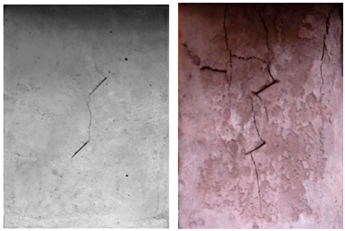 | The wing cracks connect to another wing crack or connect to pre-existing crack when it extends to a certain length. |
| Second crack shear failure | 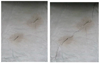 | There are second cracks produced from the pre-existing cracks which finally connect; this usually occurs when the cracks are co-planar. |
| Tension shear combined fracture failure |  | When the wing cracks expand to a certain length, the rock bridge between adjacent wing cracks is cut off in the shear direction. |
| Wing crack and second crack connection failure | 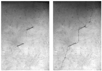 | The wing crack developed at one crack tip is connected to the second crack. |
| Wing crack shear connection failure | 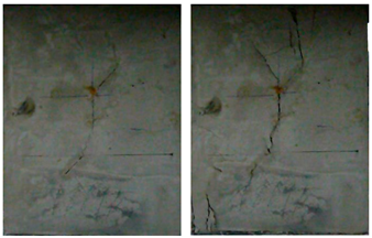 | The wing crack expands under loading and connects to another pre-existing crack. |
| Brittle failure | 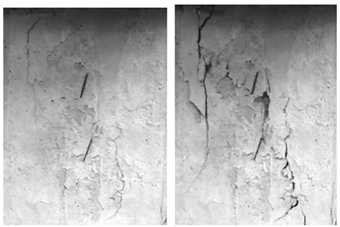 | Although there are many wing cracks or second cracks appearing during the loading process, they are not related to the specimen’s failure. |
Publisher’s Note: MDPI stays neutral with regard to jurisdictional claims in published maps and institutional affiliations. |
© 2022 by the authors. Licensee MDPI, Basel, Switzerland. This article is an open access article distributed under the terms and conditions of the Creative Commons Attribution (CC BY) license (https://creativecommons.org/licenses/by/4.0/).
Share and Cite
Liu, T.; Cui, M.; Li, Q.; Yang, S.; Yu, Z.; Sheng, Y.; Cao, P.; Zhou, K. Fracture and Damage Evolution of Multiple-Fractured Rock-like Material Subjected to Compression. Materials 2022, 15, 4326. https://doi.org/10.3390/ma15124326
Liu T, Cui M, Li Q, Yang S, Yu Z, Sheng Y, Cao P, Zhou K. Fracture and Damage Evolution of Multiple-Fractured Rock-like Material Subjected to Compression. Materials. 2022; 15(12):4326. https://doi.org/10.3390/ma15124326
Chicago/Turabian StyleLiu, Taoying, Mengyuan Cui, Qing Li, Shan Yang, Zhanfu Yu, Yeshan Sheng, Ping Cao, and Keping Zhou. 2022. "Fracture and Damage Evolution of Multiple-Fractured Rock-like Material Subjected to Compression" Materials 15, no. 12: 4326. https://doi.org/10.3390/ma15124326
APA StyleLiu, T., Cui, M., Li, Q., Yang, S., Yu, Z., Sheng, Y., Cao, P., & Zhou, K. (2022). Fracture and Damage Evolution of Multiple-Fractured Rock-like Material Subjected to Compression. Materials, 15(12), 4326. https://doi.org/10.3390/ma15124326