
Joule-Heating Effect of Thin Films with Carbon-Based Nanomaterials

 ,
,  ,
,  and
and 
Abstract
:1. Introduction
2. Materials and Methods
2.1. Materials
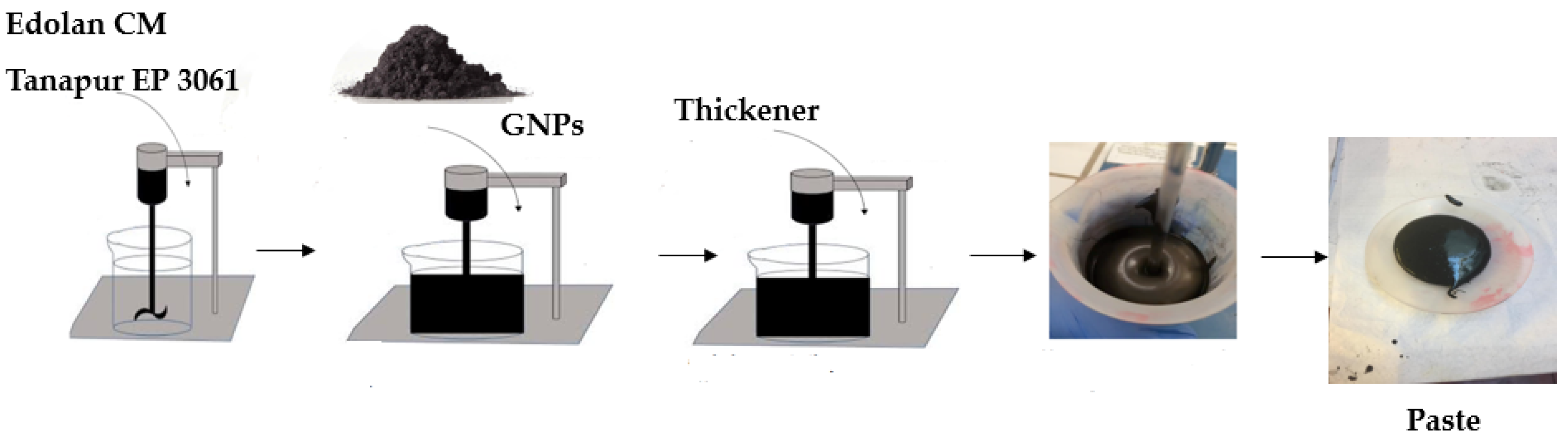
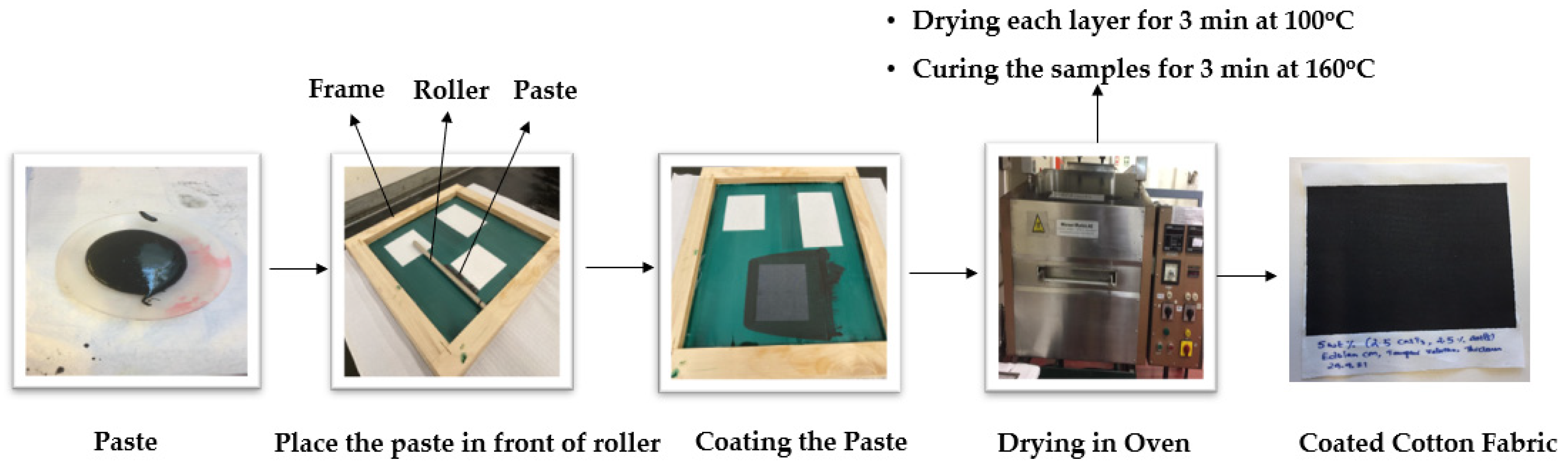
2.2. Paste Preparation
2.3. Characterization Techniques
2.3.1. Film Thickness
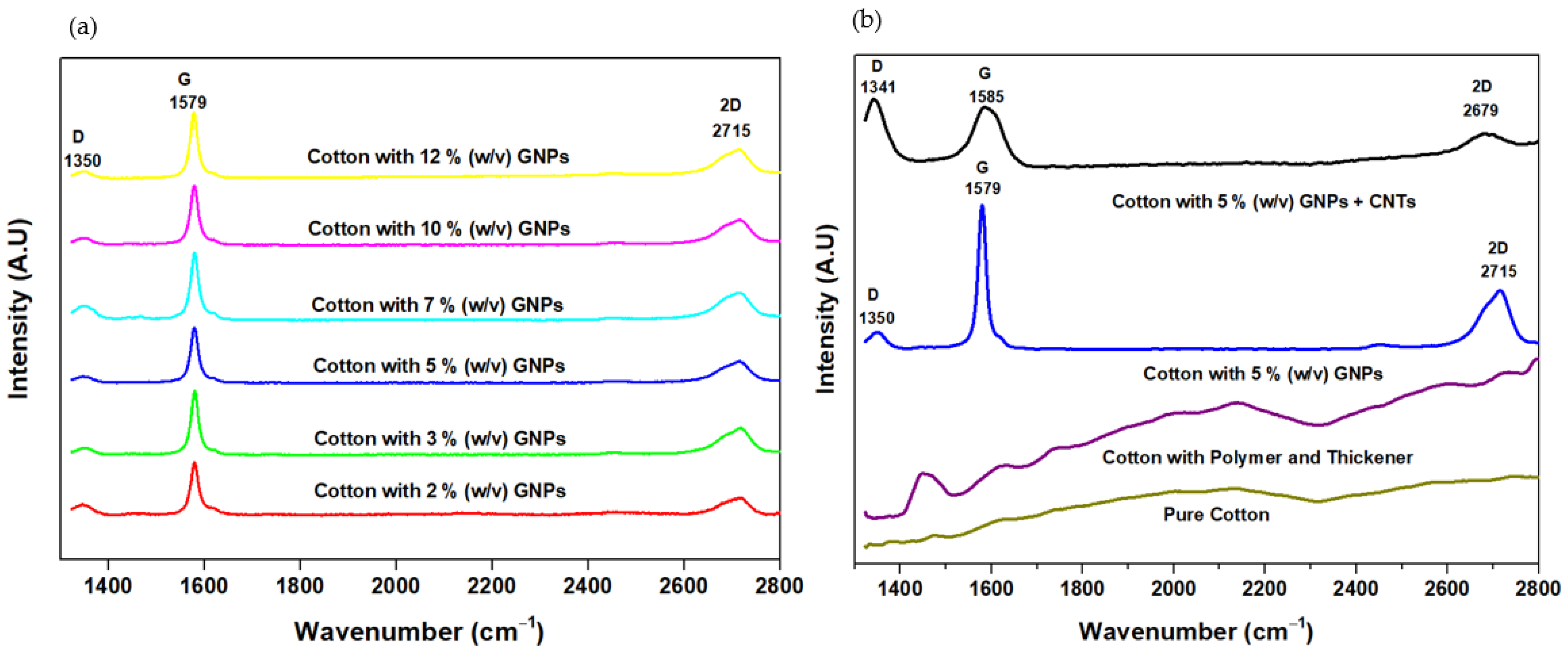
2.3.2. Raman Spectroscopy
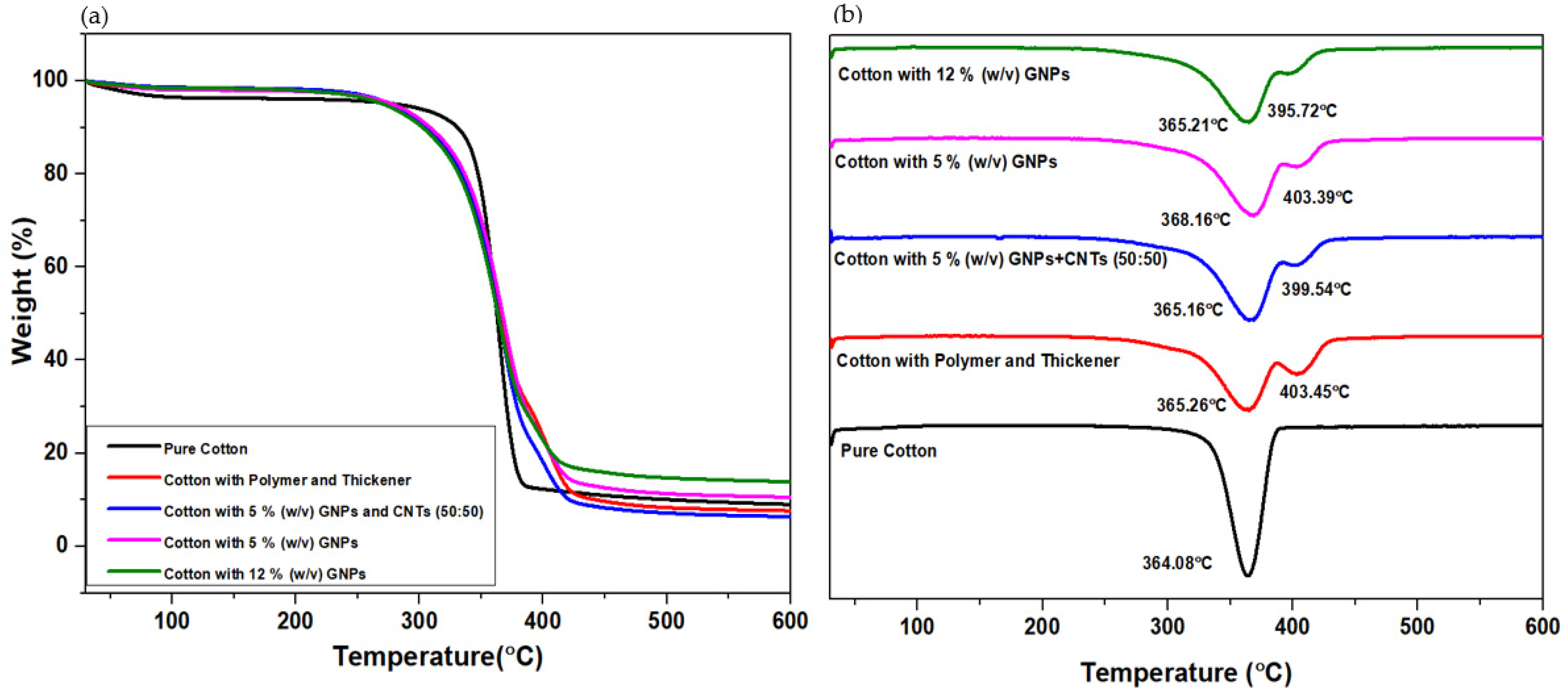
2.3.3. Thermogravimetric Analysis
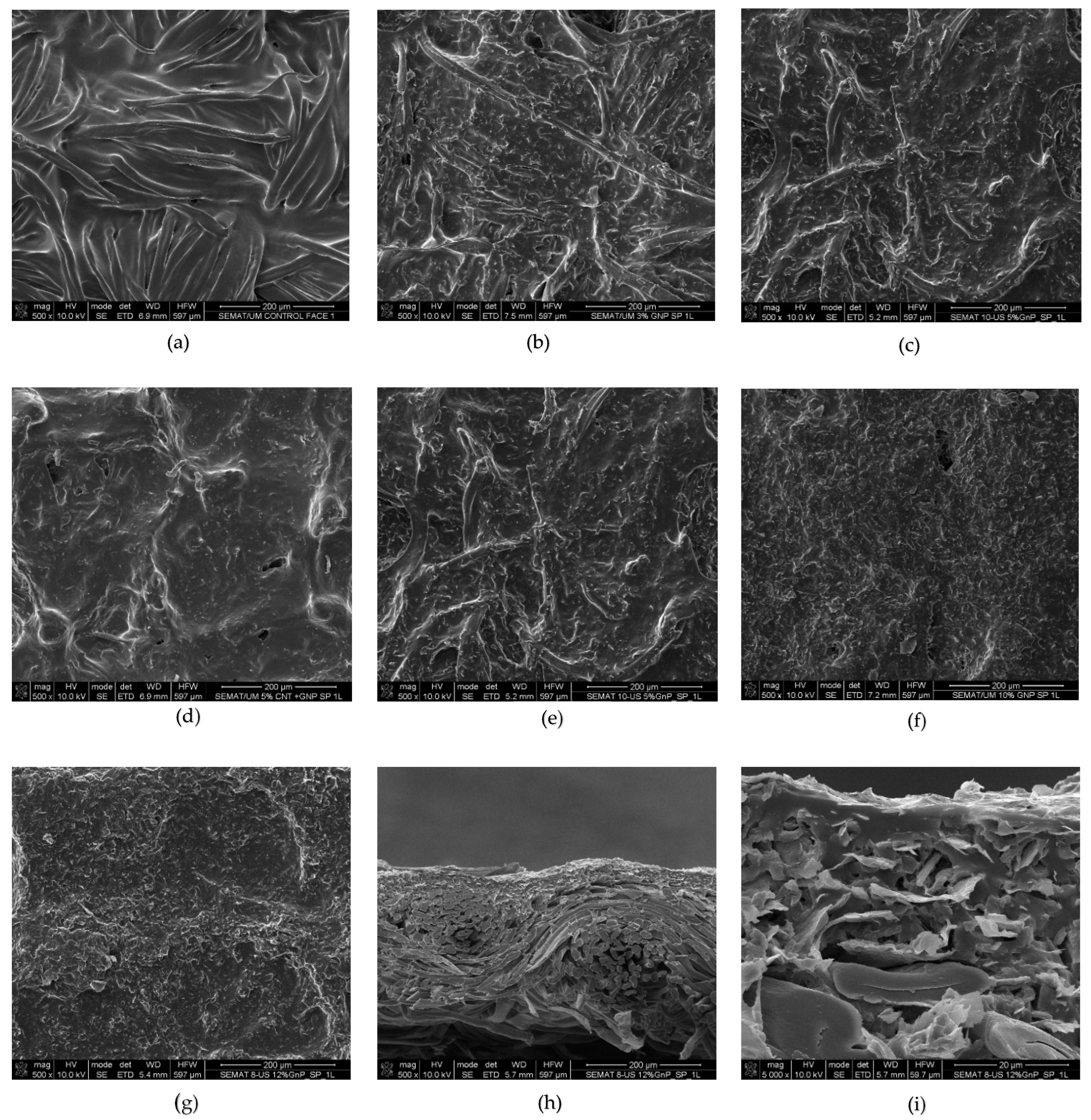
2.3.4. Field-Emission Scanning Electron Microscopy
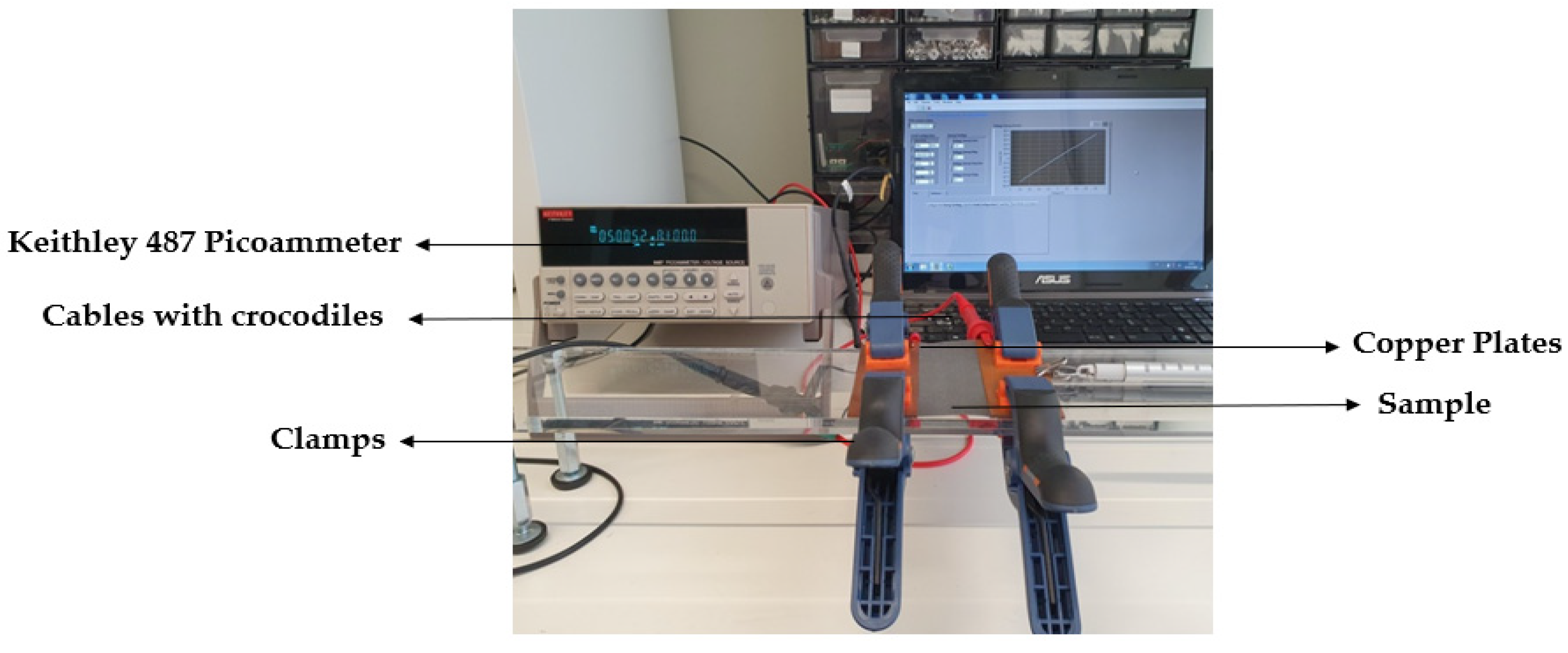
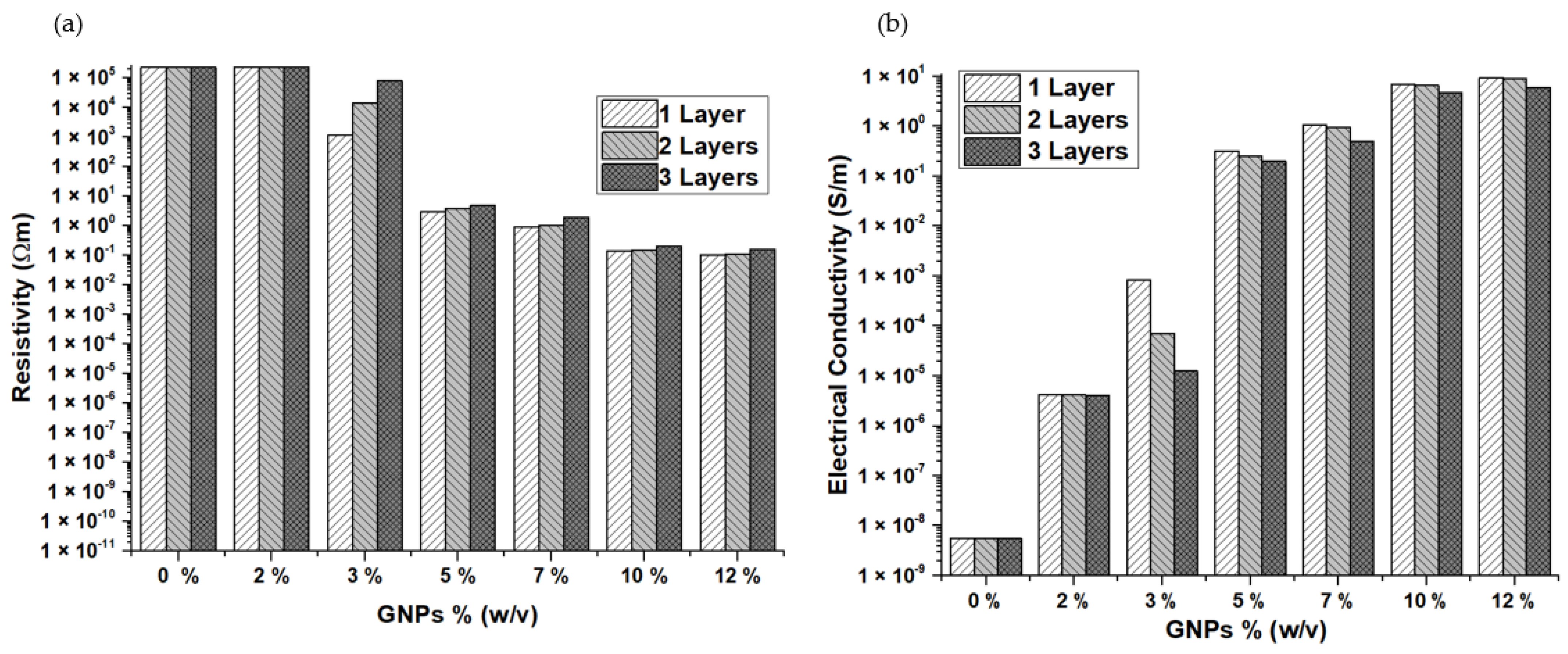
2.3.5. Electrical Conductivity

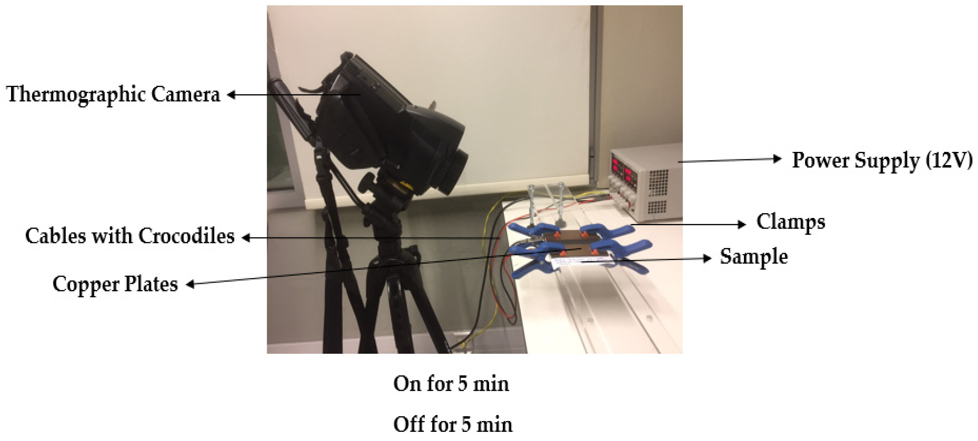
2.3.6. Joule Heating
3. Results and Discussions
3.1. Film Thickness
3.2. Raman Spectroscopy
3.3. Thermogravimetric Analysis
3.4. Field-Emission Scanning Microscopy
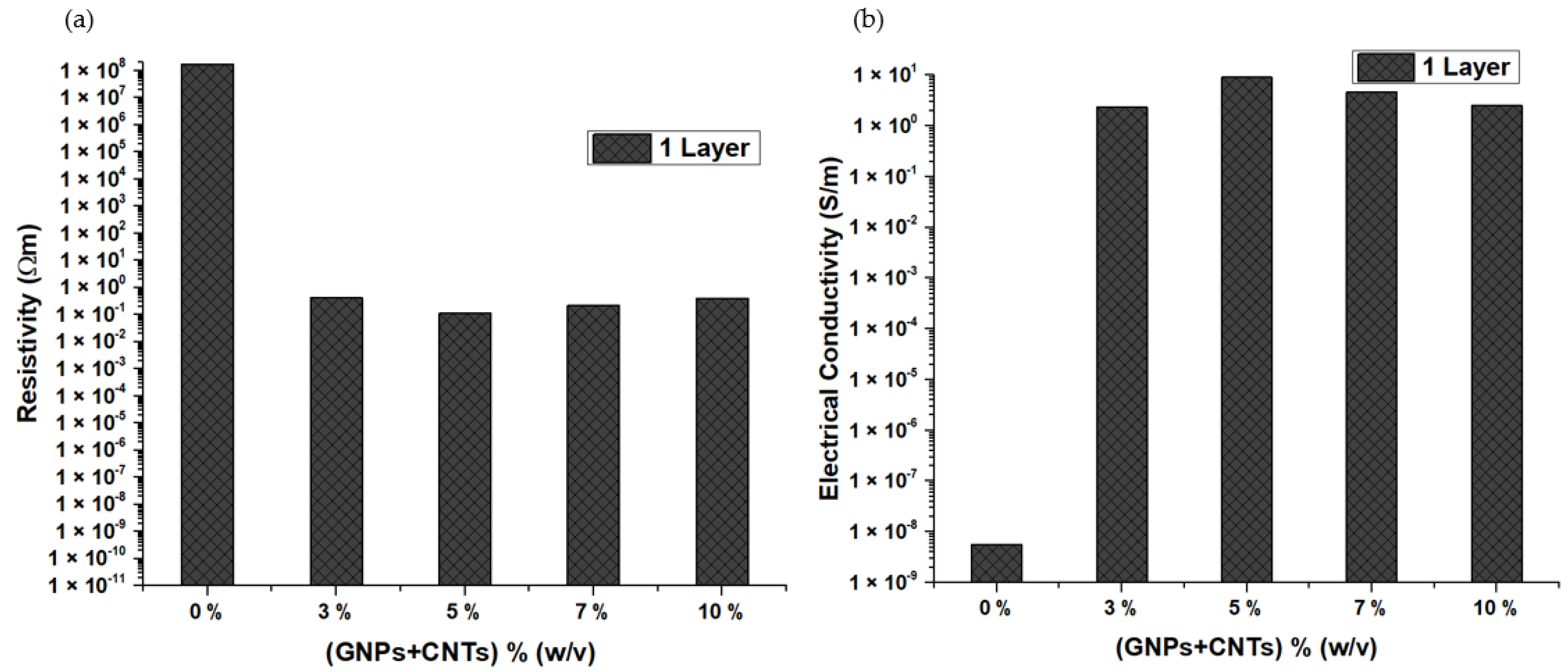
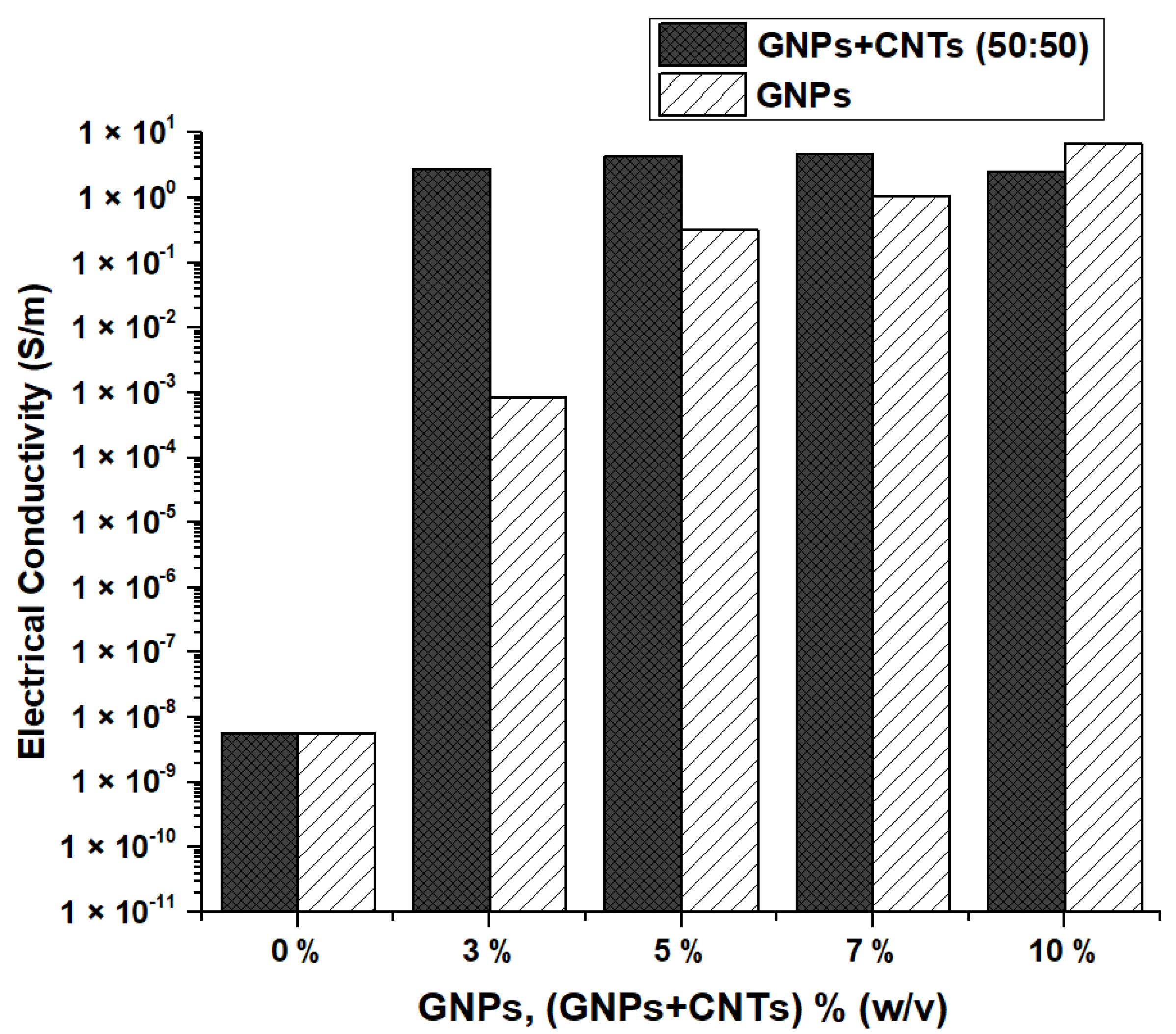
3.5. Electrical Conductivity
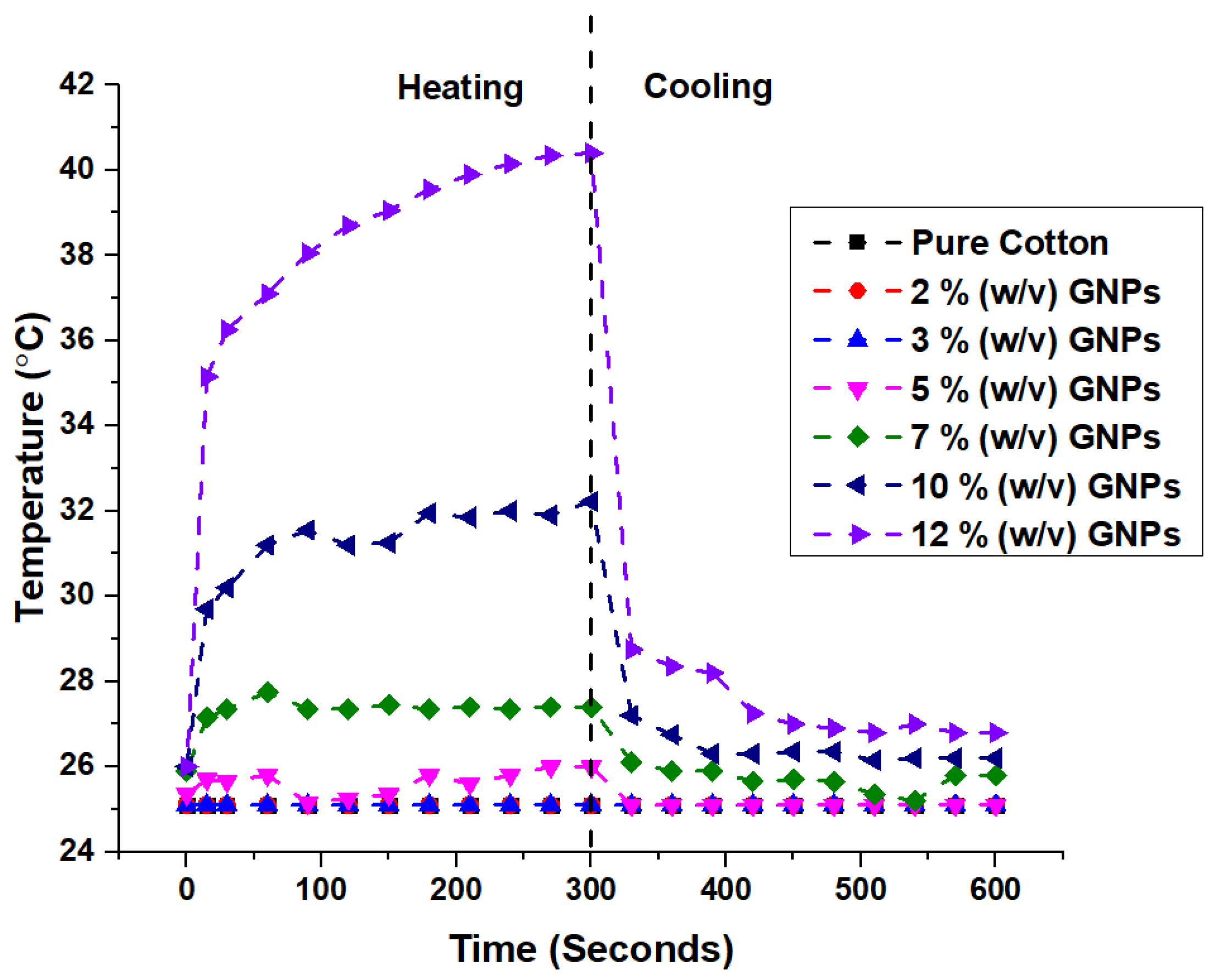
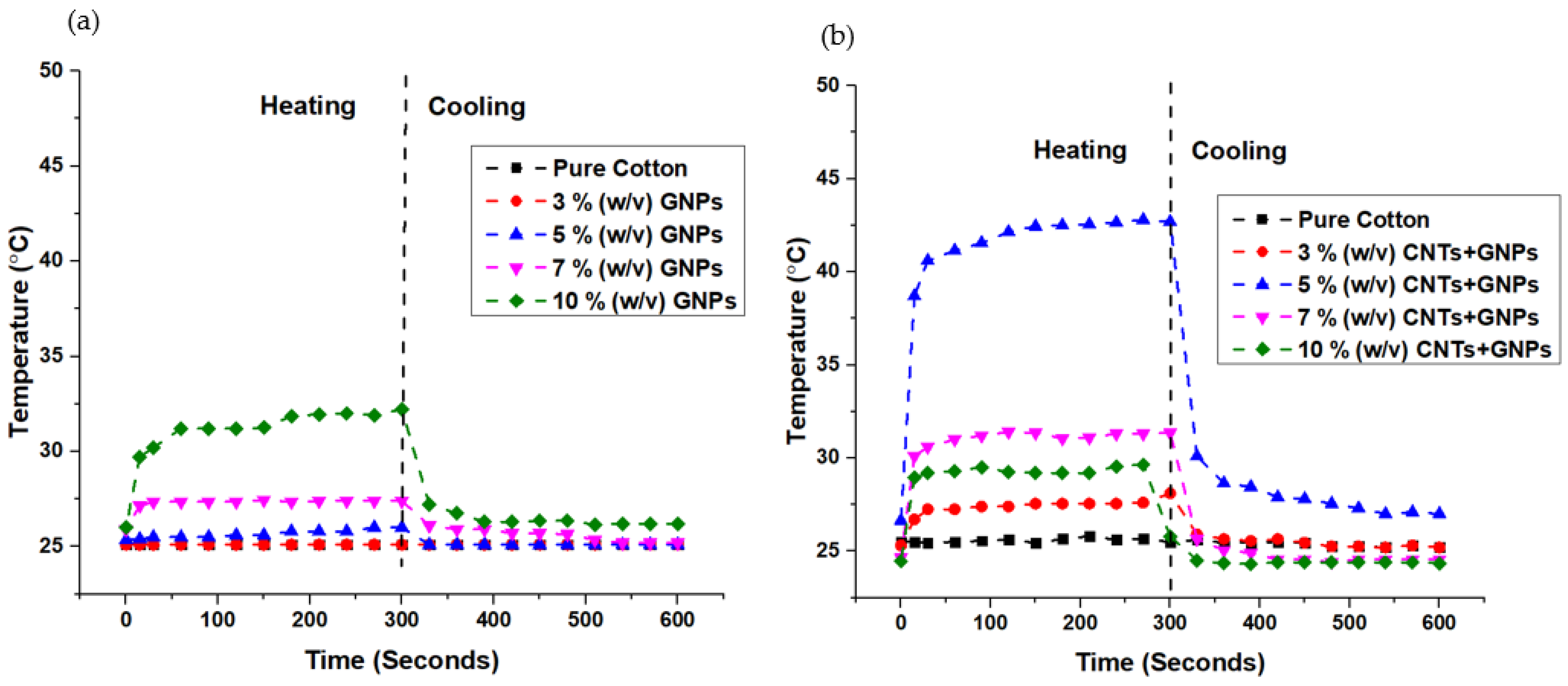
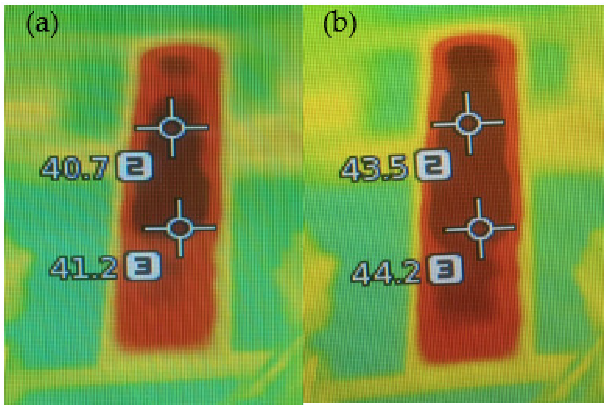
3.6. Joule Heating
4. Conclusions
Supplementary Materials
Author Contributions
Funding
Institutional Review Board Statement
Informed Consent Statement
Data Availability Statement
Acknowledgments
Conflicts of Interest
References
- Repon, M.R.; Mikučionienė, D. Progress in Flexible Electronic Textile for Heating Application: A Critical Review. Materials 2021, 14, 6540. [Google Scholar] [CrossRef] [PubMed]
- Pereira, C.; Pereira, A.M.; Freire, C.; Pinto, T.V.; Costa, R.S.; Teixeira, J.S. Nanoengineered Textiles: From Advanced Functional Nanomaterials to Groundbreaking High-Performance Clothing. In Handbook of Functionalized Nanomaterials for Industrial Applications; Elsevier: Amsterdam, The Netherlands, 2020; pp. 611–714. [Google Scholar] [CrossRef]
- Al Faruque, M.A.; Kiziltas, A.; Mielewski, D.; Naebe, M. A Facile Approach of Fabricating Electrically Conductive Knitted Fabrics Using Graphene Oxide and Textile-Based Waste Material. Polymers 2021, 13, 3003. [Google Scholar] [CrossRef] [PubMed]
- Kasaw, E.; Haile, A.; Getnet, M. Conductive Coatings of Cotton Fabric Consisting of Carbonized Charcoal for E-Textile. Coatings 2020, 10, 579. [Google Scholar] [CrossRef]
- Yang, M.; Pan, J.; Xu, A.; Luo, L.; Cheng, D.; Cai, G.; Wang, J.; Tang, B.; Wang, X. Conductive Cotton Fabrics for Motion Sensing and Heating Applications. Polymers 2018, 10, 568. [Google Scholar] [CrossRef] [Green Version]
- Wang, C.; Xia, K.; Wang, H.; Liang, X.; Yin, Z.; Zhang, Y. Advanced Carbon for Flexible and Wearable Electronics. Adv. Mater. 2019, 31, 1–37. [Google Scholar] [CrossRef]
- Bae, H.; Jang, B.C.; Park, H.; Jung, S.H.; Lee, H.M.; Park, J.Y.; Jeon, S.B.; Son, G.; Tcho, I.W.; Yu, K.; et al. Functional Circuitry on Commercial Fabric via Textile-Compatible Nanoscale Film Coating Process for Fibertronics. Nano Lett. 2017, 17, 6443–6452. [Google Scholar] [CrossRef]
- Kayacan, O.; Bulgun, E.Y. Heating Behaviors of Metallic Textile Structures. Int. J. Cloth. Sci. Technol. 2009, 21, 127–136. [Google Scholar] [CrossRef]
- Zhang, L.; Baima, M.; Andrew, T.L. Transforming Commercial Textiles and Threads into Sewable and Weavable Electric Heaters. ACS Appl. Mater. Interfaces 2017, 9, 32299–32307. [Google Scholar] [CrossRef]
- Rahman, M.J.; Mieno, T. Conductive Cotton Textile from Safely Functionalized Carbon Nanotubes. J. Nanomater. 2015, 2015, 978484. [Google Scholar] [CrossRef]
- Ren, J.; Wang, C.; Zhang, X.; Carey, T.; Chen, K.; Yin, Y.; Torrisi, F. Environmentally-Friendly Conductive Cotton Fabric as Flexible Strain Sensor Based on Hot Press Reduced Graphene Oxide. Carbon 2017, 111, 622–630. [Google Scholar] [CrossRef] [Green Version]
- Ahmed, A.; Jalil, M.A.; Hossain, M.M.; Moniruzzaman, M.; Adak, B.; Islam, M.T.; Parvez, M.S.; Mukhopadhyay, S. A PEDOT: PSS and Graphene-Clad Smart Textile-Based Wearable Electronic Joule Heater with High Thermal Stability. J. Mater. Chem. C 2020, 8, 16204–16215. [Google Scholar] [CrossRef]
- Koçanalı, A.; Apaydın Varol, E. An Experimental Study on the Electrical and Thermal Performance of Reduced Graphene Oxide Coated Cotton Fabric. Int. J. Energy Res. 2021, 45, 12915–12927. [Google Scholar] [CrossRef]
- Pereira, P.; Ferreira, D.P.; Araújo, J.C.; Ferreira, A.; Fangueiro, R. The Potential of Graphene Nanoplatelets in the Development of Smart and Multifunctional Ecocomposites. Polymers 2020, 12, 2189. [Google Scholar] [CrossRef] [PubMed]
- Moreira, I.P.; Sanivada, U.K.; Bessa, J.; Cunha, F.; Fangueiro, R. A Review of Multiple Scale Fibrous and Composite Systems for Heating Applications. Molecules 2021, 26, 3686. [Google Scholar] [CrossRef]
- Catauro, M.; Barrino, F.; Scolaro, C.; Visco, A. Surface Modifications Induced in UHMWPE Based Nanocomposites during the Ageing in Simulated Synovial Fluid. Macromol. Symp. 2020, 389, 4–7. [Google Scholar] [CrossRef]
- Sanes, J.; Sánchez, C.; Pamies, R.; Avilés, M.D.; Bermúdez, M.D. Extrusion of Polymer Nanocomposites with Graphene and Graphene Derivative Nanofillers: An Overview of Recent Developments. Materials 2020, 13, 549. [Google Scholar] [CrossRef] [Green Version]
- Mármol, G.; Sanivada, U.K.; Fangueiro, R. Effect of Gnps on the Piezoresistive, Electrical and Mechanical Properties of Pha and Pla Films. Fibers 2021, 9, 86. [Google Scholar] [CrossRef]
- Hu, X.; Tian, M.; Qu, L.; Zhu, S.; Han, G. Multifunctional Cotton Fabrics with Graphene/Polyurethane Coatings with Far-Infrared Emission, Electrical Conductivity, and Ultraviolet-Blocking Properties. Carbon 2015, 95, 625–633. [Google Scholar] [CrossRef]
- Cataldi, P.; Ceseracciu, L.; Athanassiou, A.; Bayer, I.S. Healable Cotton-Graphene Nanocomposite Conductor for Wearable Electronics. ACS Appl. Mater. Interfaces 2017, 9, 13825–13830. [Google Scholar] [CrossRef]
- Mohan, V.B.; Santhana Krishnan, S.; Bhattacharyya, D. Manufacturing and Characterization of Novel Silicone/Natural Fabric/Graphene-Based Functional Composites for Human Body Motion Sensing. Polym. Compos. 2021, 42, 3493–3507. [Google Scholar] [CrossRef]
- Ghosh, S.; Remanan, S.; Mondal, S.; Ganguly, S.; Das, P.; Singha, N.; Das, N.C. An Approach to Prepare Mechanically Robust Full IPN Strengthened Conductive Cotton Fabric for High Strain Tolerant Electromagnetic Interference Shielding. Chem. Eng. J. 2018, 344, 138–154. [Google Scholar] [CrossRef]
- Li, J.; Tan, Y.J.; Chen, Y.F.; Wu, H.; Guo, S.; Wang, M. Constructing Multiple Interfaces in Polydimethylsiloxane/Multi-Walled Carbon Nanotubes Nanocomposites by the Incorporation of Cotton Fibers for High-Performance Electromagnetic Interference Shielding and Mechanical Enhancement. Appl. Surf. Sci. 2019, 466, 657–665. [Google Scholar] [CrossRef]
- Dai, M.; Zhai, Y.; Zhang, Y. A Green Approach to Preparing Hydrophobic, Electrically Conductive Textiles Based on Waterborne Polyurethane for Electromagnetic Interference Shielding with Low Reflectivity. Chem. Eng. J. 2021, 421, 127749. [Google Scholar] [CrossRef]
- Verma, M.; Chauhan, S.S.; Dhawan, S.K.; Choudhary, V. Graphene Nanoplatelets/Carbon Nanotubes/Polyurethane Composites as Efficient Shield against Electromagnetic Polluting Radiations. Compos. Part B Eng. 2017, 120, 118–127. [Google Scholar] [CrossRef]
- Kuo, C.C.; Liu, C.C.; He, S.C.; Chang, J.T.; He, J.L. The Influences of Thickness on the Optical and Electrical Properties of Dual-Ion-Beam Sputtering-Deposited Molybdenum-Doped Zinc Oxide Layer. J. Nanomater. 2011, 2011, 140697. [Google Scholar] [CrossRef]
- Puech, P.; Kandara, M.; Paredes, G.; Moulin, L.; Weiss-Hortala, E.; Kundu, A.; Ratel-Ramond, N.; Plewa, J.-M.; Pellenq, R.; Monthioux, M. Analyzing the Raman Spectra of Graphenic Carbon Materials from Kerogens to Nanotubes: What Type of Information Can Be Extracted from Defect Bands? C—J. Carbon Res. 2019, 5, 69. [Google Scholar] [CrossRef] [Green Version]
- Kumar, D.K.; Suazo-Davila, D.; García-Torres, D.; Cook, N.P.; Ivaturi, A.; Hsu, M.H.; Martí, A.A.; Cabrera, C.R.; Chen, B.; Bennett, N.; et al. Low-Temperature Titania-Graphene Quantum Dots Paste for Flexible Dye-Sensitised Solar Cell Applications. Electrochim. Acta 2019, 305, 278–284. [Google Scholar] [CrossRef] [Green Version]
- Huang, J.; Yang, X.; Her, S.C.; Liang, Y.M. Carbon Nanotube/Graphene Nanoplatelet Hybrid Film as a Flexible Multifunctional Sensor. Sensors 2019, 19, 317. [Google Scholar] [CrossRef] [Green Version]
- Kumar, D.K.; Swami, S.K.; Dutta, V.; Chen, B.; Bennett, N.; Upadhyaya, H.M. Scalable Screen-Printing Manufacturing Process for Graphene Oxide Platinum Free Alternative Counter Electrodes in Efficient Dye Sensitized Solar Cells. FlatChem 2019, 15, 100105. [Google Scholar] [CrossRef]
- Chang, H.P.; Liu, H.C.; Tan, C.S. Using Supercritical CO2-Assisted Mixing to Prepare Graphene/Carbon Nanotube/Epoxy Nanocomposites. Polymer 2015, 75, 125–133. [Google Scholar] [CrossRef]
- Murphy, H.; Papakonstantinou, P.; Okpalugo, T.I.T. Raman Study of Multiwalled Carbon Nanotubes Functionalized with Oxygen Groups. J. Vac. Sci. Technol. B Microelectron. Nanom. Struct. 2006, 24, 715. [Google Scholar] [CrossRef] [Green Version]
- Tav, A.; Öz, Y.; Akyildiz, H.İ. Thermal and Mechanical Properties of Sol-Gel Silica Coated Fabrics. Eur. J. Sci. Technol. 2021, 31, 309–319. [Google Scholar] [CrossRef]
- Miranda, C.; Castaño, J.; Valdebenito-Rolack, E.; Sanhueza, F.; Toro, R.; Bello-Toledo, H.; Uarac, P.; Saez, L. Copper-Polyurethane Composite Materials: Particle Size Effect on the Physical-Chemical and Antibacterial Properties. Polymers 2020, 12, 1934. [Google Scholar] [CrossRef]
- Quan, H.; Zhang, B.Q.; Zhao, Q.; Yuen, R.K.K.; Li, R.K.Y. Facile Preparation and Thermal Degradation Studies of Graphite Nanoplatelets (GNPs) Filled Thermoplastic Polyurethane (TPU) Nanocomposites. Compos. Part A Appl. Sci. Manuf. 2009, 40, 1506–1513. [Google Scholar] [CrossRef]
- Kim, H.; Lee, S. Characterization of Electrical Heating Textile Coated by Graphene Nanoplatelets/PVDF-HFP Composite with Various High Graphene Nanoplatelet Contents. Polymers 2019, 11, 928. [Google Scholar] [CrossRef] [PubMed] [Green Version]
- Moraes, M.R.; Alves, A.C.; Toptan, F.; Martins, M.S.; Vieira, E.M.F.; Paleo, A.J.; Souto, A.P.; Santos, W.L.F.; Esteves, M.F.; Zille, A. Glycerol/PEDOT:PSS Coated Woven Fabric as a Flexible Heating Element on Textiles. J. Mater. Chem. C 2017, 5, 3807–3822. [Google Scholar] [CrossRef] [Green Version]
- Taherian, R.; Ghorbani, M.M. Investigation of the Electrical Properties of Polymer/Carbon Composites Exposed to Joule Heating and Heat Treatment. ECS J. Solid State Sci. Technol. 2017, 6, M3019–M3027. [Google Scholar] [CrossRef]
- Yang, H.; Yao, X.; Yuan, L.; Gong, L.; Liu, Y. Strain-Sensitive Electrical Conductivity of Carbon Nanotube-Graphene-Filled Rubber Composites under Cyclic Loading. Nanoscale 2019, 11, 578–586. [Google Scholar] [CrossRef]


| Mechanical Properties | Electrical Properties | Other Properties | |||
|---|---|---|---|---|---|
| Young’s Modulus | 1 TPa | Electrical Conductivity | 104 S/cm | Thermal Conductivity | 5300 W/mK |
| Fracture Strength | 130 GPa | Electron Mobility | 250,000 cm2/V.s | Specific Surface Area | 2630 m2/g |
| Optical Transmittance | 97.7% | ||||
| w/v % | GNPs Samples | GNPs + CNTs Samples | ||
|---|---|---|---|---|
| 1 Layer | 2 Layers | 3 Layers | 1 Layer | |
| 2 | 0.04 | 0.06 | 0.08 | - |
| 3 | 0.04 | 0.07 | 0.08 | 0.05 |
| 5 | 0.04 | 0.06 | 0.09 | 0.05 |
| 7 | 0.04 | 0.07 | 0.10 | 0.04 |
| 10 | 0.05 | 0.08 | 0.11 | 0.04 |
| 12 | 0.05 | 0.08 | 0.11 | - |
Publisher’s Note: MDPI stays neutral with regard to jurisdictional claims in published maps and institutional affiliations. |
© 2022 by the authors. Licensee MDPI, Basel, Switzerland. This article is an open access article distributed under the terms and conditions of the Creative Commons Attribution (CC BY) license (https://creativecommons.org/licenses/by/4.0/).
Share and Cite
Sanivada, U.K.; Esteves, D.; Arruda, L.M.; Silva, C.A.; Moreira, I.P.; Fangueiro, R. Joule-Heating Effect of Thin Films with Carbon-Based Nanomaterials. Materials 2022, 15, 4323. https://doi.org/10.3390/ma15124323
Sanivada UK, Esteves D, Arruda LM, Silva CA, Moreira IP, Fangueiro R. Joule-Heating Effect of Thin Films with Carbon-Based Nanomaterials. Materials. 2022; 15(12):4323. https://doi.org/10.3390/ma15124323
Chicago/Turabian StyleSanivada, Usha Kiran, Dina Esteves, Luisa M. Arruda, Carla A. Silva, Inês P. Moreira, and Raul Fangueiro. 2022. "Joule-Heating Effect of Thin Films with Carbon-Based Nanomaterials" Materials 15, no. 12: 4323. https://doi.org/10.3390/ma15124323
APA StyleSanivada, U. K., Esteves, D., Arruda, L. M., Silva, C. A., Moreira, I. P., & Fangueiro, R. (2022). Joule-Heating Effect of Thin Films with Carbon-Based Nanomaterials. Materials, 15(12), 4323. https://doi.org/10.3390/ma15124323