Abstract
Evolution of damage and fracture behavior of fiber-reinforced mini ceramic-matrix composites (mini-CMCs) under tensile load are related to internal multiple damage mechanisms, i.e., fragmentation of the brittle matrix, crack defection, and fibers fracture and pullout. In this paper, considering multiple micro internal damage mechanisms and related models, a micromechanical constitutive stress–strain relationship model is developed to predict the nonlinear mechanical behavior of mini-CMCs under tensile load corresponding to different damage domains. Relationships between multiple micro internal damage mechanisms mentioned above and tensile micromechanical multiple damage parameters are established. Experimental tensile nonlinear behavior, internal damage evolution, and micromechanical tensile damage parameters corresponding to different damage domains of two different types of mini-CMCs are predicted. The effects of constitutive properties and damage-related parameters on nonlinear behavior of mini-CMCs are discussed.
1. Introduction
With the development of thermodynamics, the advancement of component integrated design technology, the weight reduction brought by structural simplification and the comprehensive development of material technology, the thrust-to-weight ratio of aeroengines has gradually increased. However, on the premise of maintaining the engine layout and not changing the conventional metal materials, the improvement of aerodynamic, thermal, component design and structural weight reduction techniques can only increase the ratio between the thrust and weight of the aeroengines to approximately 14. For aeroengines with ratios between the thrust and a weight of approximately 12–15 or higher, more breakthroughs must be made in new materials, new process applications and new structural design, such as polymer-matrix composites (PMCs) or metal-matrix composites (MMCs) for cold section components in aeroengine and ceramic-matrix composites (CMCs) for hot section components in aeroengines. Two main types of CMCs are used in aeroengines, including, C/SiC and SiC/SiC. For aeroengines, the operating temperatures of C/SiC and SiC/SiC are approximately 1650 °C and 1450 °C, respectively. Increasing the operating temperature of SiC fibers can raise the operating temperature of SiC/SiC to 1650 °C. Results show that the application of CMCs in the hot section components of the combustion chamber, turbine, and nozzle can increase the operating temperature of the aeroengine by 300–500 °C, reduce the weight by 50–70% and increase the thrust by 30–100% [1,2,3,4].
In order to safely and confidently implement CMCs in different thermo-structural component applications, one should understand the complexity of designing with such brittle composite systems. The mechanical behavior of minicomposites can be used to analyze the internal complex damage evolution of woven composites [5,6,7,8]. Many in situ monitoring techniques, including acoustic emission (AE), X-ray microtomography, and acousto-ultrasonics (AU), have been used to detect and reveal internal damage evolution mechanisms in minicomposites [9,10,11,12]. Under tensile load, the damages in the minicomposites can be divided into different stages and the damage stages are affected by the fiber type and interphases [13,14,15,16]. Heat-treatment at elevated temperature causes damages in the fiber and interphase, leading to the degradation of tensile performance of mini-CMCs [17,18,19,20,21].
The objective in the present analysis is to build the relationship between tensile nonlinear damage behavior and multiple micro internal damage mechanisms of mini-CMCs. A micromechanical nonlinear stress–strain relationship model is given to predict the tensile stress–strain relationship of mini-CMCs when either partial or complete interfacial debonding occurs. Experimental tensile damage evolution and related multiple microdamage parameters of two different mini-CMCs are predicted. Effects of constitutive properties and damage-related parameters on damage and fracture of mini-CMCs are analyzed.
2. Theoretical Analysis
The tensile nonlinear behavior of mini-CMCs is mainly attributed to multiple microdamage mechanisms. Through in situ experimental observations and monitoring on internal damage state [12,13], damage evolution and fracture of mini-CMCs under tensile load can be divided into three main domains, including:
- (1)
- Domain I, the linear domain.
- (2)
- Domain II, the nonlinear domain due to microdamages of matrix fragmentation.
- (3)
- Domain III, the secondary linear and final fracture domain due to gradual fibers fracture and pullout.
In this section, the micromechanical nonlinear constitutive relationship of three damage domains mentioned above is developed and related to the microdamage state of matrix fragmentation and fiber fractures and pullouts inside of mini-CMCs. A micromechanical parameter of interface debonding fraction η is adopted to describe composite internal damage evolution.
2.1. Domain I
In Domain I, no damages occur in mini-CMCs, and the linear relationship between applied stress σ and composite stress–strain εc can be determined by Equation (1) [4].
where Ec is the elastic modulus of the undamaged composite.
2.2. Domain II
When multiple microdamage mechanisms occur in mini-CMCs, the micro stress field of the damaged composite is affected by composite constitutive properties (i.e., volume of the fiber and matrix Vf and Vm, and fiber radius rf) and damage state (i.e., fragmentation length of the brittle matrix lc, and crack defection length at the interface ld). The fiber axial stress distribution can be determined by Equation (2) [4].
where τi the interface frictional shear stress, σfo and σmo the axial stress of the fiber and matrix in the interface bonding region, and ρ the shear–lag model parameter. The stochastic model in Equation (3) can be used to determine the fragmentation length of the brittle matrix [22], and the relationship between the applied stress and debonding length at the interface is obtained by Equation (4) [23].
where lsat is the saturation matrix fragmentation length, σm is the stress carried by the matrix, σR is the characteristic stress for matrix fragmentation, and ζd is the debonding energy of the interface.
The composite strain εc is equal to the strain of intact fibers, and the nonlinear stress–strain constitutive relationship can be determined by Equation (5).
where Ef is the elastic modulus of the fiber, η is the ratio between debonding length ld and half of fragmentation length of the brittle matrix lc, αf and αc are the axial thermal expansion coefficient of the fiber and the composite, and ΔT is the temperature difference between testing and fabricated temperature.
2.3. Domain III
Upon approaching saturation of fragmentation of the brittle matrix, some fibers gradually fracture and pullout inside of the minicomposite. Considering intact and broken fiber in the different damage regions, the axial stress of the fiber can be determined by Equation (6) [4].
where Φ is the stress of unbroken fiber, which can be determined by Equation (7) [24].
where is the average pullout length of a broken fiber, and P the probability of fiber being broken.
Considering fibers fracture inside of mini-CMCs, the nonlinear stress–strain relationship at damage Domain III is acquired by Equation (5).
3. Experimental Comparison
Nonlinear tensile damage and fracture behavior of two different types of mini-CMCs are predicted. The effect of heat treatment at 1300 and 1500 °C on tensile nonlinear damage development behavior of mini-CMCs at room temperature is also analyzed. The material properties of different mini-CMCs are listed in Table 1.

Table 1.
Material properties of unidirectional SiC/SiC and C/SiC minicomposite.
3.1. SiC/SiC Minicomposite
Figure 1 shows the experimental data and theoretical predicted results of tensile nonlinear curves and fragmentation density of brittle matrix versus applied stress curves of Hi-NicalonTM SiC/SiC mini-CMC. The predicted results of tensile curves and fragmentation density of brittle matrix evolution curves both agreed well with experimental data. Three main damage domains are obtained from the nonlinear tensile curve, including:
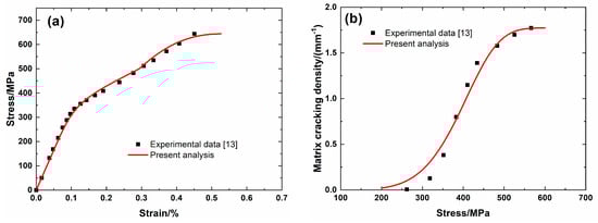
Figure 1.
(a) Tensile nonlinear stress–strain curves; and, (b) matrix fragmentation density versus applied stress curves of Hi-NicalonTM SiC/SiC mini ceramic-matrix composites (mini-CMCs).
- (1)
- Domain I, the linear domain. The domain starts from the initial loading to the first matrix fragmentation stress σmc = 200 MPa, and the first fragmentation density of the matrix is approximately λmc = 0.02/mm, and the corresponding composite tensile strain is approximately εc = 0.06%.
- (2)
- Domain II, the nonlinear region due to matrix fragmentation. The domain starts from σmc = 200 MPa to the saturation matrix fragmentation stress σsat = 560 MPa, and the saturation fragmentation density of the matrix is approximately λsat = 1.76/mm, and the composite tensile strain is approximately εc = 0.34%.
- (3)
- Domain III, the secondary linear and final fracture domain. The domain starts from σsat = 560 MPa to composite tensile strength σuts = 644 MPa.
Figure 2 shows experimental data and theoretical predicted results of tensile nonlinear curves and fragmentation density of the brittle matrix versus applied stress curves of Hi-NicalonTM Type S SiC/SiC minicomposite. The predicted results of tensile curves and fragmentation density of brittle matrix evolution curves agree with experimental data. Three main damage domains are obtained from the nonlinear tensile curve, including:
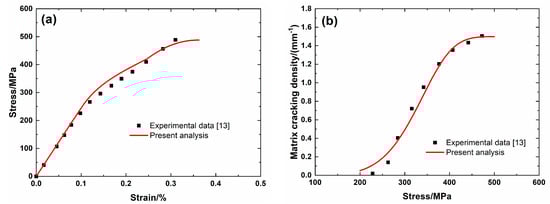
Figure 2.
(a) Tensile nonlinear stress–strain curves; and, (b) matrix fragmentation density versus applied stress curves of Hi-NicalonTM Type S SiC/SiC mini-CMC.
- (1)
- Domain I, the linear domain. The domain starts from initial loading to σmc = 200 MPa with λmc = 0.05/mm and εc = 0.08%.
- (2)
- Domain II, the nonlinear region due to matrix fragmentation. The domain starts from σmc = 200 MPa to σsat = 470 MPa with λsat = 1.49/mm and εc = 0.3%.
- (3)
- Domain III, the secondary linear and final fracture region. The domain starts from σsat = 470 MPa to σuts = 488 MPa.
Figure 3 shows experimental data and theoretical predicted results of tensile nonlinear curves and fragmentation density evolution of brittle matrix curves versus applied stress of TyrannoTM ZMI SiC/SiC minicomposite. Predicted results of tensile curves and fragmentation density of brittle matrix evolution curves agree well with experimental data. Three main damage domains are obtained from the nonlinear tensile curve, including:
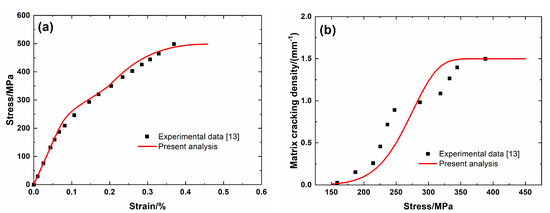
Figure 3.
(a) Tensile nonlinear stress–strain curves; and, (b) matrix fragmentation density versus applied stress curves of TyrannoTM ZMI SiC/SiC mini-CMC.
- (1)
- Domain I, the linear region. The domain starts from initial loading to σmc = 150 MPa with λmc = 0.01/mm and εc = 0.05%.
- (2)
- Domain II, the nonlinear region due to matrix fragmentation. The domain starts from σmc = 150 MPa to σsat = 350 MPa with λmc = 1.49/mm and εc = 0.198%.
- (3)
- Domain III, the secondary linear and final fracture region. The domain starts from σsat = 350 MPa to σuts = 498 MPa.
Figure 4 shows experimental data and theoretical predicted results of tensile nonlinear curves and fragmentation density evolution of the brittle matrix versus applied stress of SiC/SiC minicomposite without heat treatment. The predicted results of tensile curves and fragmentation density evolution of the brittle matrix curves agree well with experimental data. Three main damage domains are obtained from the nonlinear tensile curve, including:
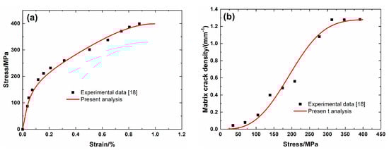
Figure 4.
(a) Tensile nonlinear stress–strain curves; and, (b) matrix fragmentation density versus applied stress curves of SiC/SiC mini-CMC without heat treatment.
- (1)
- Domain I, the linear region. The domain starts from initial loading to σmc = 35 MPa with λmc = 0.04/mm and εc = 0.013%.
- (2)
- Domain II, the nonlinear region. The domain starts from the σmc = 35 MPa to σsat = 340 MPa with λsat = 1.27/mm and εc = 0.6%.
- (3)
- Domain III, the secondary linear and final fracture domain. The domain starts from σsat = 340 MPa to σuts = 399 MPa.
Figure 5 shows experimental data and theoretical predicted results of tensile nonlinear curves and fragmentation density evolution of brittle matrix versus applied stress of SiC/SiC minicomposite after heat treatment at 1300 °C. The predicted results of tensile curves and fragmentation density evolution of brittle matrix versus applied stress curves agree well with experimental data. Three main damage domains are obtained from the nonlinear tensile curve, including:
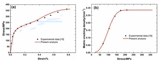
Figure 5.
(a) Tensile nonlinear stress–strain curves; and, (b) matrix fragmentation density versus applied stress curves of SiC/SiC mini-CMC after heat treatment at 1300 °C in Ar atmosphere.
- (1)
- Domain I, the linear region. The domain starts from initial loading to σmc = 50 MPa with λmc = 0.02/mm and εc = 0.012%.
- (2)
- Domain II, the nonlinear region due to matrix fragmentation. The domain starts from σmc = 50 MPa to σsat = 210 MPa with λsat = 0.28/mm and εc = 0.13%.
- (3)
- Domain III, the secondary linear and final fracture region. The domain starts from σsat = 210 MPa to σuts = 362 MPa.
Figure 6 shows experimental data and theoretical predicted results of tensile nonlinear curves and fragmentation density evolution of brittle matrix versus applied stress of SiC/SiC minicomposite after heat treatment at 1500 °C. The predicted results of tensile curves and fragmentation density of brittle matrix versus applied stress curves both agree well with experimental data. Three main damage domains are obtained from the nonlinear tensile curve, including:
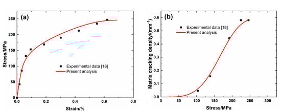
Figure 6.
(a) Tensile nonlinear stress–strain curves; and, (b) matrix fragmentation density versus applied stress curves of SiC/SiC mini-CMC after heat treatment at 1500 °C in Ar atmosphere.
- (1)
- Domain I, the linear region. The domain starts from initial loading to σmc = 50 MPa with λmc = 0.005/mm and εc = 0.017%.
- (2)
- Domain II, the nonlinear region. The domain starts from σmc = 50 MPa to σsat = 220 MPa with λsat = 0.58/mm and εc = 0.39%.
- (3)
- Domain III, the secondary linear and final fracture domain. The domain starts from σsat = 220 MPa to σuts = 246 MPa.
3.2. C/SiC Minicomposite
Figure 7 shows experimental data and theoretical predicted results of tensile curves and the interface debonding fraction versus applied stress curves of unidirectional C/SiC minicomposite. The predicted results of tensile curves agree with experimental data, as shown in Figure 7a, and the composite tensile fractures at the condition of partial interface debonding, as shown in Figure 7b. Three main damage domains are obtained from the nonlinear tensile curve, including:
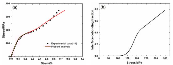
Figure 7.
(a) Tensile nonlinear stress–strain curves; and, (b) the interface debonding fraction versus applied stress curves of unidirectional T–300TM C/SiC mini-CMC.
- (1)
- Domain I, the linear region. The domain starts from initial loading to σmc = 130 MPa.
- (2)
- Domain II, the nonlinear region. The domain starts from σmc = 130 MPa to σsat = 250 MPa.
- (3)
- Domain III, the secondary linear and final fracture domain. The domain starts from σsat = 250 MPa to σuts = 348 MPa. The interface debonding fraction increases to 2ld/lc = 0.78 at tensile strength σuts = 348 MPa.
4. Discussion
In this section, the constitutive properties and damage-related parameters on tensile nonlinear stress–strain curves of SiC/SiC mini-CMC are discussed.
4.1. Effect of Fiber Volume
Figure 8 shows the tensile nonlinear curves and the evolution of interface debonding fraction for different fiber volumes. For low fiber volume Vf = 25%, the debonding fraction increases from η (σd = 166 MPa) = 0 to η (σuts = 521 MPa) = 0.33, and the failure strain of the composite is εf (σuts = 521 MPa) = 0.6%. For high fiber volume Vf = 30%, the debonding fraction increases from η (σd = 204 MPa) = 0 to η (σuts = 626 MPa) = 0.32, and the failure strain of the composite is εf = 0.64%. At high fiber volume, the debonding fraction at the same applied stress decreases, and the composite strain at nonlinear Domain II decreases, and the composite tensile strength and failure strain increase.
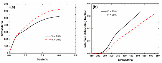
Figure 8.
(a) Tensile nonlinear stress–strain curves; and, (b) the debonding fraction versus applied stress curves of SiC/SiC mini-CMC for different fiber volumes.
4.2. Effect of Interface Properties
Figure 9 shows the tensile nonlinear curves and the evolution of the interface debonding fraction for different interface shear stresses. For low interface shear stress τi = 20 MPa, the debonding fraction increases from η (σd = 166 MPa) = 0 to η (σuts = 521 MPa) = 0.5, and the failure strain of the composite is εf = 0.73%. For high interface shear stress τi = 40 MPa, the debonding fraction increases from η (σd = 168 MPa) = 0 to η (σuts = 521 MPa) = 0.25; and the failure strain of the composite is εf = 0.25%. At high interface shear stress, the debonding fraction at the same applied stress decreases, and the composite strain at nonlinear Domain II decreases, and the composite failure strain decreases.
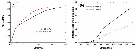
Figure 9.
(a) Tensile nonlinear stress–strain curves; and, (b) the fraction of the interface debonding versus applied stress curves of SiC/SiC mini-CMC for different interface shear stress.
Figure 10 shows the tensile nonlinear curves and the evolution of the interface debonding fraction for different interface debonding energy. For low interface debonding energy ζd = 4 J/m2, the debonding fraction increases from η (σd = 192 MPa) = 0 to η (σuts = 521 MPa) = 0.31, and the failure strain of the composite is εf = 0.59%. For high interface debonding energy ζd = 6 J/m2, the debonding fraction increases from η (σd = 234 MPa) = 0 to η (σuts = 521 MPa) = 0.57, and the failure strain of the composite is εf = 0.57%. At high interface debonding energy, the interface debonding stress increases, the debonding fraction at the same applied stress decreases, and the composite strain during nonlinear Domain II decreases, and the failure strain of the composite decreases.
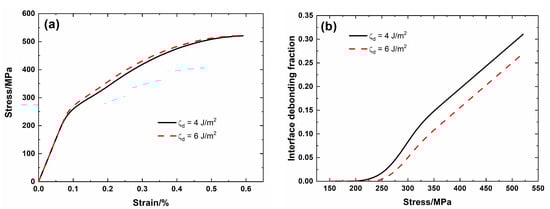
Figure 10.
(a) Tensile nonlinear stress–strain curves; and, (b) the fraction of the interface debonding versus applied stress curves of SiC/SiC mini-CMC for different interface debonding energy.
5. Conclusions
In this paper, the tensile damage and fracture behavior of two different mini-CMCs are investigated. Multiple microdamage mechanisms of matrix fragmentation, fibers failure and pullout are considered in the analysis of tensile nonlinear curves. Experimental tensile nonlinear curves and internal damage evolution of SiC/SiC and C/SiC mini-CMCs are predicted. The effects of material properties and damage-related parameters on tensile damage and fracture at different domains are analyzed.
- (1)
- Predicted tensile nonlinear curves and matrix fragmentation density evolution curves agree with experimental data, and the matrix fragmentation approaches saturation before tensile fracture, and the interface partial debonding remains till tensile fracture.
- (2)
- Microdamage parameters of first matrix fragmentation stress, saturation matrix fragmentation stress and density, composite tensile strength and failure strain are obtained from tensile stress–strain curves and can be used to characterize tensile nonlinear behavior of mini-CMCs.
- (3)
- At higher fiber volume, the debonding fraction at the same applied stress decreases, and the composite strain at nonlinear Domain II decreases, and the composite tensile strength and failure strain increase.
- (4)
- At higher interface shear stress and interface debonding energy, the debonding fraction at the same applied stress decreases, and the composite strain at nonlinear Domain II decreases, and the failure strain of the composite decreases.
Author Contributions
Conceptualization: Z.Z. and L.L.; methodology: L.L.; writing—original draft preparation: Z.Z., Y.L. and L.L.; writing—review and editing: D.F. All authors have read and agreed to the published version of the manuscript.
Funding
This research was funded by Fundamental Research Funds for the Central Universities of China, grant number NS2019038.
Acknowledgments
The authors also wish to thank four anonymous reviewers and editors for their helpful comments on an earlier version of the paper.
Conflicts of Interest
The authors declare no conflict of interest. The funders had no role in the design of the study; in the collection, analyses, or interpretation of data; in the writing of the manuscript, or in the decision to publish the results.
References
- Padture, N.P.; Gell, M.; Jordan, E.H. Thermal barrier coatings for gas-turbine engine applications. Science 2002, 296, 280–284. [Google Scholar] [CrossRef] [PubMed]
- Naslain, R.R. SiC-matrix composites: Nonbrittle ceramics for thermo-structural application. Int. J. Appl. Ceram. Technol. 2005, 2, 75–84. [Google Scholar] [CrossRef]
- Zok, F.W. Ceramic-matrix composites enable revolutionary gains in turbine efficiency. Am. Ceram. Soc. Bull. 2016, 95, 22–28. [Google Scholar]
- Li, L.B. Damage, Fracture and Fatigue of Ceramic-Matrix Composites; Springer Nature Singapore Pte Ltd.: Singapore, 2018. [Google Scholar]
- Morscher, G.N.; Martinez-Fernandez, J. Determination of interfacial properties using a single-fiber microcomposite test. J. Am. Ceram. Soc. 1996, 79, 1083–1091. [Google Scholar] [CrossRef]
- Li, H.; Morscher, G.; Lee, J.; Lee, W. Tensile and stress-rupture behavior of SiC/SiC minicomposite containing chemically vapor deposited zirconia interphase. J. Am. Ceram. Soc. 2004, 87, 1726–1733. [Google Scholar] [CrossRef]
- Yu, H.; Zhou, X.; Zhang, W.; Peng, H.; Zhang, C. Mechanical behavior of SiCf/SiC composites with alternating PyC/SiC multilayer interphases. Mater. Des. 2013, 44, 320–324. [Google Scholar] [CrossRef]
- Krishnan, S.; Vijay, V.; Siva, S.; Painuly, A.; Naithani, N.; Devasia, R. A comparative study on Cf/PyC/SiC minicomposites prepared via CVI process for hypersonic engine application. Int. J. Appl. Ceram. Technol. 2018, 15, 1110–1123. [Google Scholar] [CrossRef]
- Mamiya, T.; Kagawa, Y. Tensile fracture behavior and strength of surface-modified SiTiCO fiber SiC-matrix minicomposites fabricated by the PIP process. J. Am. Ceram. Soc. 2000, 83, 433–435. [Google Scholar] [CrossRef]
- Martinez-Fernandez, J.; Morscher, G.N. Room and elevated temperature tensile properties of single tow Hi-Nicalon, carbon interphase, CVI SiC matrix minicomposites. J. Eur. Ceram. Soc. 2000, 20, 2627–2636. [Google Scholar] [CrossRef]
- Chateau, C.; Gelebart, L.; Bornert, M.; Crepin, J.; Boller, E.; Sauder, C.; Ludwig, W. In situ X-ray microtomography characterization of damage in SiC/SiC minicomposites. Compos. Sci. Technol. 2011, 71, 916–924. [Google Scholar] [CrossRef]
- Maillet, E.; Godin, N.; R’Mili, M.; Reynaud, P.; Fantozzi, G.; Lamon, J. Damage monitoring and identification in SiC/SiC minicomposites using combined acousto-ultrasonics and acoustic emission. Compos. Part A 2014, 57, 8–15. [Google Scholar] [CrossRef]
- Almansour, A.S. Use of Single-Tow Ceramic Matrix Minicomposites to Determine Fundamental Room and Elevated Temperature Properties. Ph.D. Thesis, University of Akron, Akron, OH, USA, 2017. [Google Scholar]
- Wang, Y.; Cheng, L.; Zhang, L. Prediction of the mechanical behavior of a minicomposite based on grey Verhulst models. Ceram. Silik. 2017, 61, 372–377. [Google Scholar] [CrossRef][Green Version]
- Zhang, S.; Gao, X.; Chen, J.; Dong, H.; Song, Y. Strength model of the matrix element in SiC/SiC composites. Mater. Des. 2016, 101, 66–71. [Google Scholar] [CrossRef]
- Zhang, S.; Gao, X.; Chen, J.; Dong, H.; Song, Y.; Zhang, H. Effect of micro-damage on the nonlinear constitutive behavior of SiC/SiC minicomposites. J. Ceram. Sci. Technol. 2016, 7, 341–348. [Google Scholar]
- Ochiai, S.; Kimura, S.; Tanaka, H.; Tanaka, M.; Hojo, M.; Morishita, K.; Okuda, H.; Nakayama, H.; Tamura, M.; Shibata, K.; et al. Residual strength of PIP-processed SiC/SiC single-tow minicomposite exposed at high temperatures in air as a function of exposure temperature and time. Compos. Part A 2004, 35, 41–50. [Google Scholar] [CrossRef]
- Han, X.; Gao, X.; Song, Y. Effect of heat treatment on the microstructure and mechanical behavior of SiC/SiC mini-composites. Mater. Sci. Eng. A 2019, 746, 94–104. [Google Scholar] [CrossRef]
- Guo, S.; Kagawa, Y. Tensile fracture behavior of continuous SiC fiber-reinforced SiC matrix composites at elevated temperatures and correlation to in situ constituent properties. J. Eur. Ceram. Soc. 2002, 22, 2349–2356. [Google Scholar] [CrossRef]
- Yang, C.; Zhang, L.; Wang, B.; Huang, T.; Jiao, G. Tensile behavior of 2D-C/SiC composites at elevated temperatures: Experiment and modeling. J. Eur. Ceram. Soc. 2017, 37, 1281–1290. [Google Scholar] [CrossRef]
- Li, L.B. Modeling matrix multicracking development of fiber-reinforced ceramic-matrix composites considering fiber debonding. Int. J. Appl. Ceram. Technol. 2019, 16, 97–107. [Google Scholar] [CrossRef]
- Curtin, W.A. Multiple matrix cracking in brittle matrix composites. Acta Met. Mater. 1993, 41, 1369–1377. [Google Scholar] [CrossRef]
- Gao, Y.; Mai, Y.; Cotterell, B. Fracture of fiber-reinforced materials. J. Appl. Math. Phys. 1988, 39, 550–572. [Google Scholar] [CrossRef]
- Curtin, W.A. Theory of mechanical properties of ceramic-matrix composites. J. Am. Ceram. Soc. 1991, 74, 2837–2845. [Google Scholar] [CrossRef]
© 2020 by the authors. Licensee MDPI, Basel, Switzerland. This article is an open access article distributed under the terms and conditions of the Creative Commons Attribution (CC BY) license (http://creativecommons.org/licenses/by/4.0/).