Effects of High CaO Fly Ash and Sulfate Activator as a Finer Binder for Cementless Grouting Material


Abstract
1. Introduction
2. Experimental Procedure
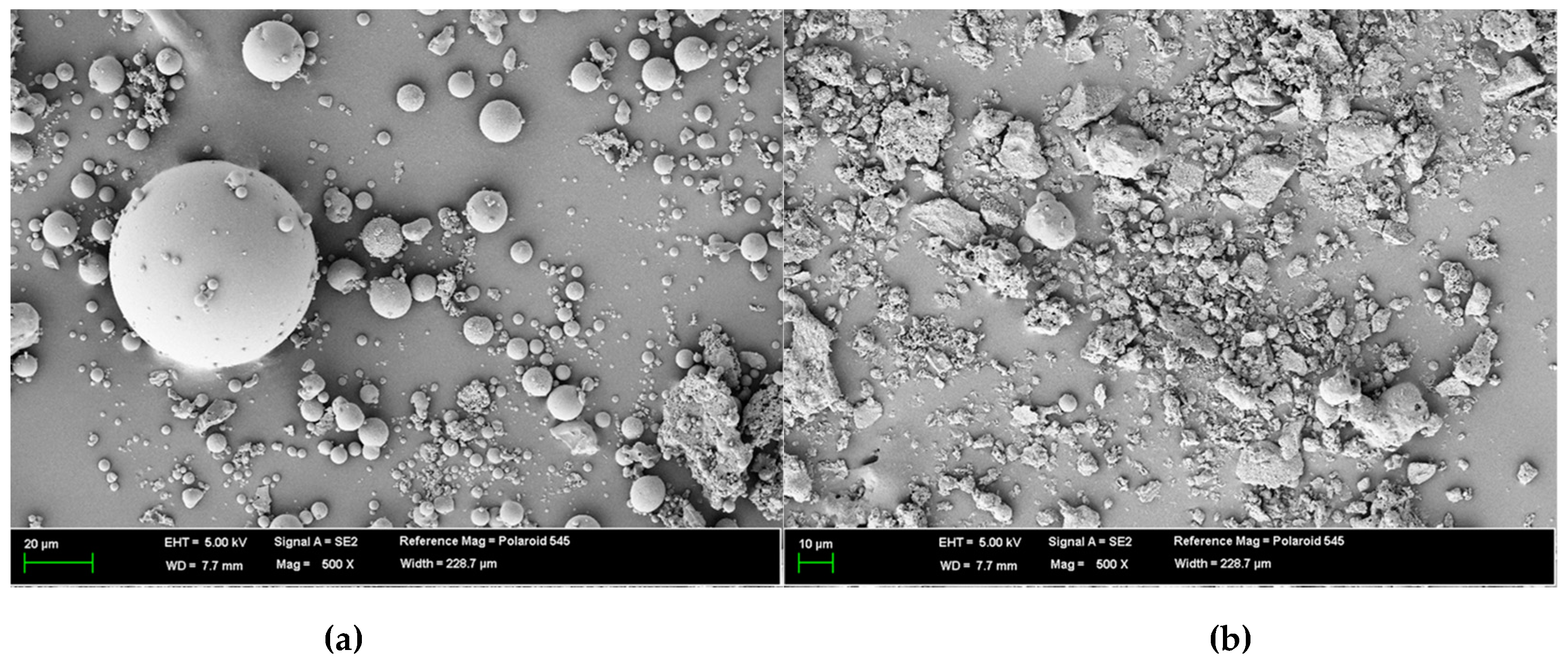
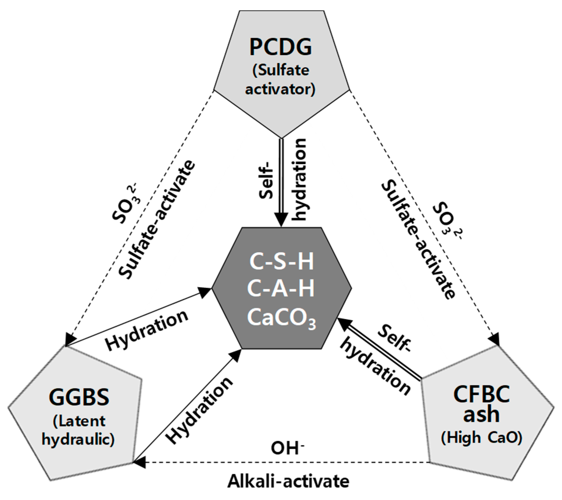
2.1. Materials
2.2. Procedure
2.3. Test Methods
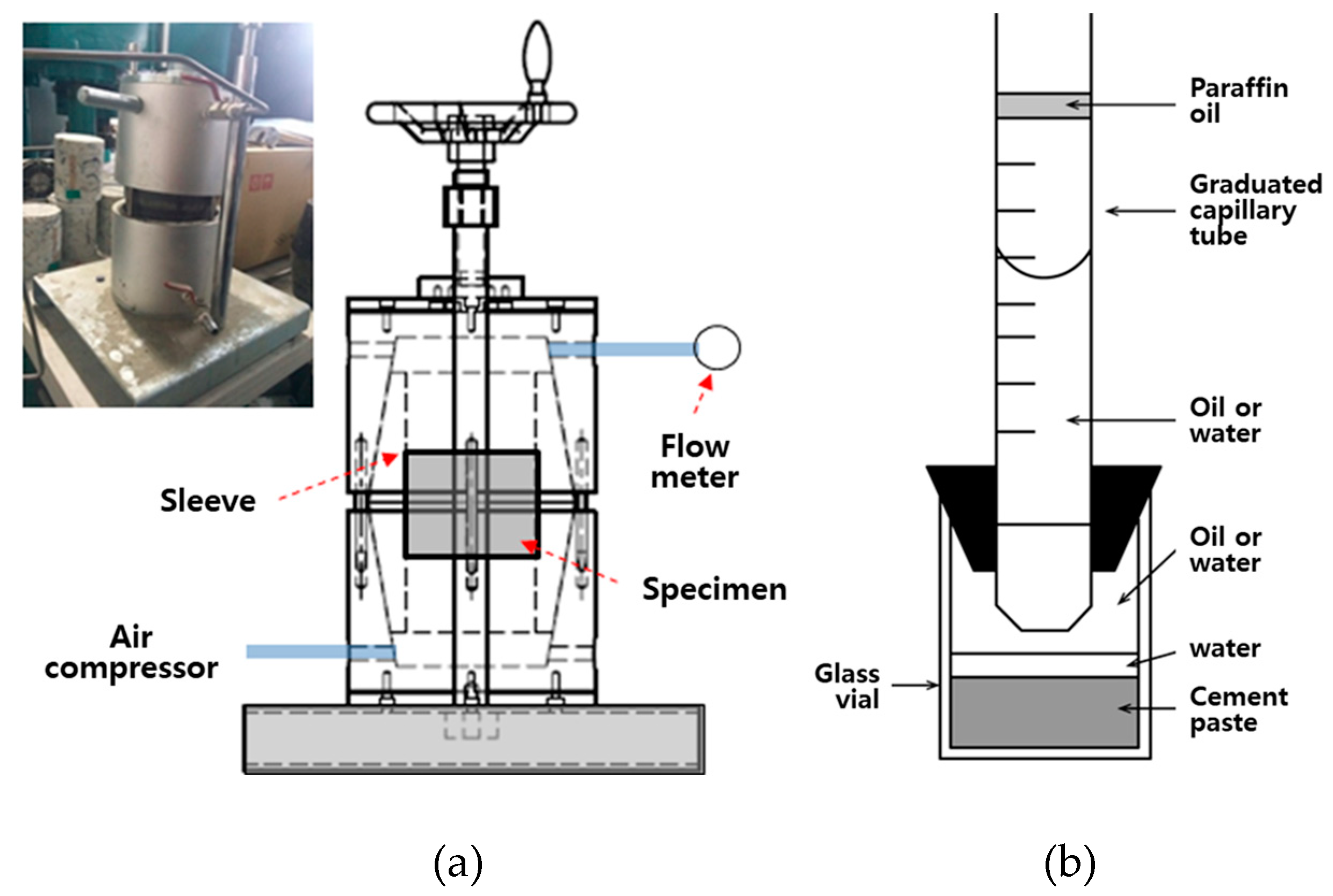
2.3.1. Gel Time
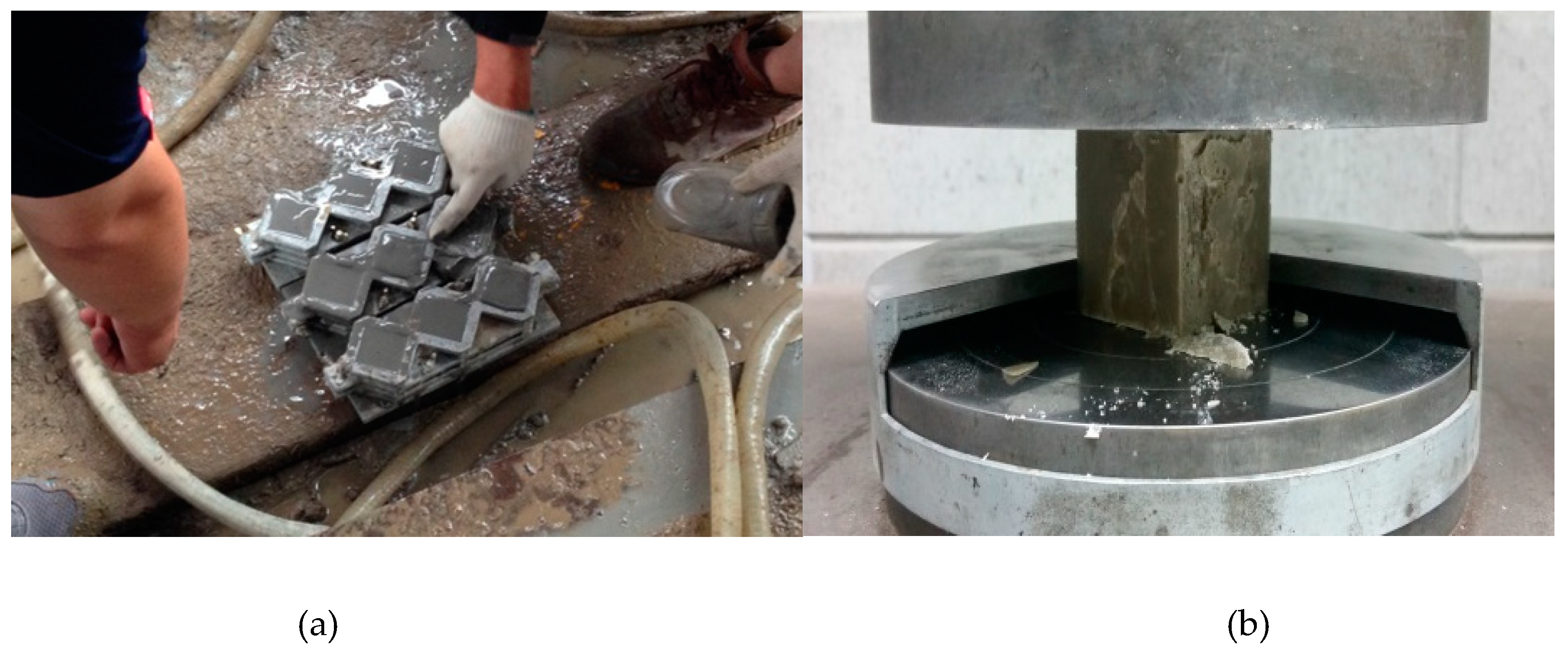
2.3.2. Homogel Strength
2.3.3. Chemical Shrinkage and Air Permeability
- c: correction factor (1/60 × 10−6)
- η: viscosity of measured gas (Pa·s)
- h: height of specimen (mm)
- d: diameter of specimen (mm)
- p0: atmospheric pressure (kPa)
- p1: gas pressure (kPa)
- qv: gas flow rate (cm3/min).
2.3.4. Other Test Items
3. Results and Discussion
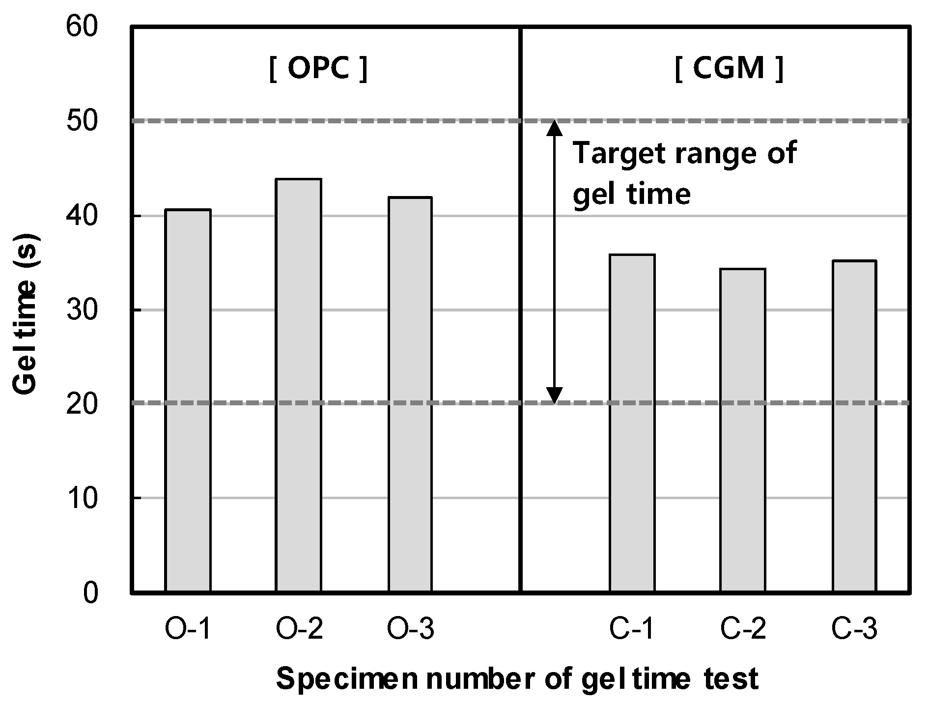
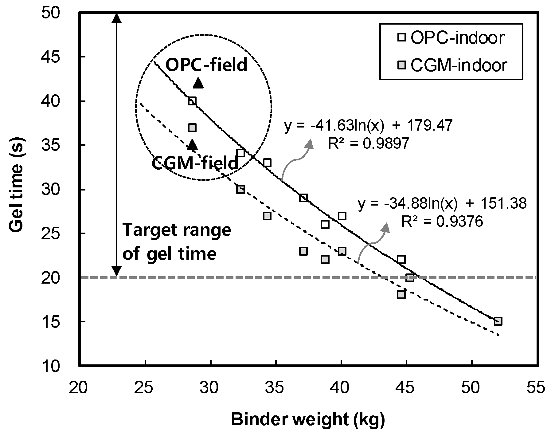
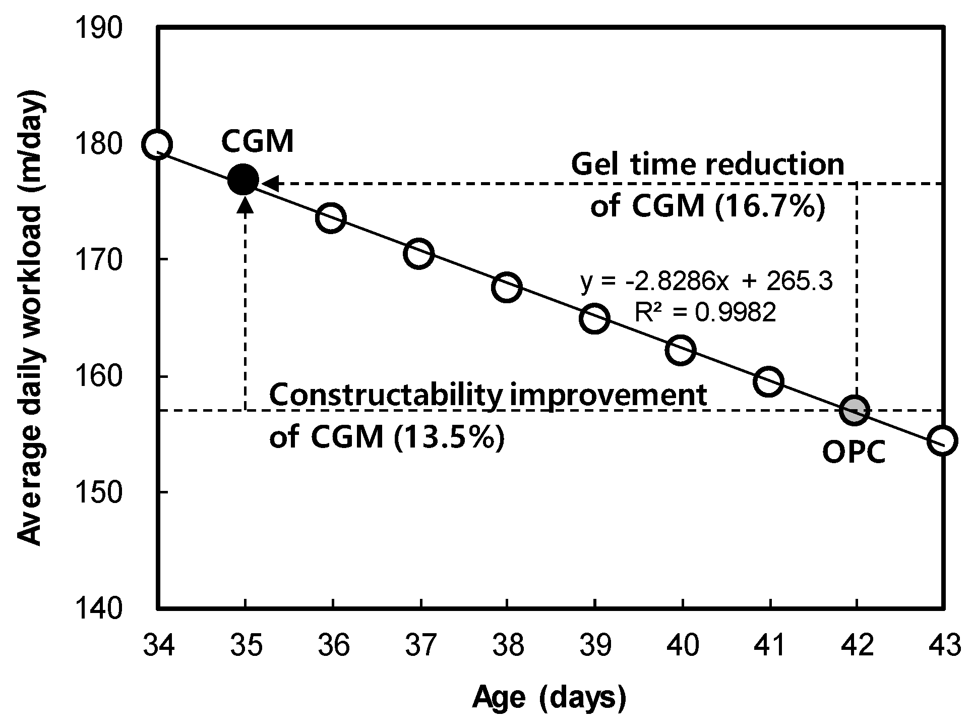
3.1. Effects of CGM on Shortening Gel Time
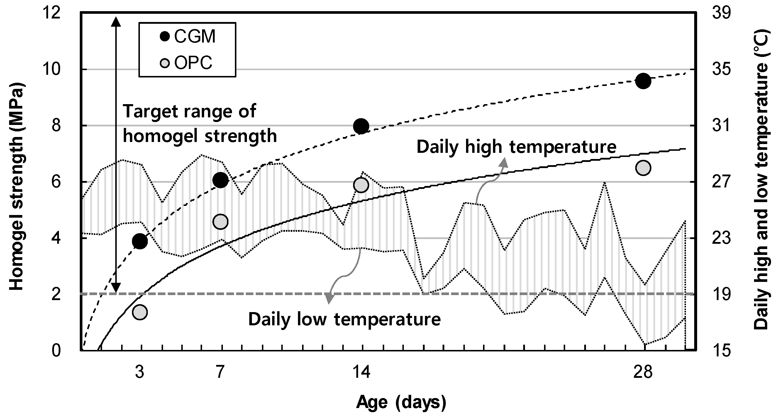
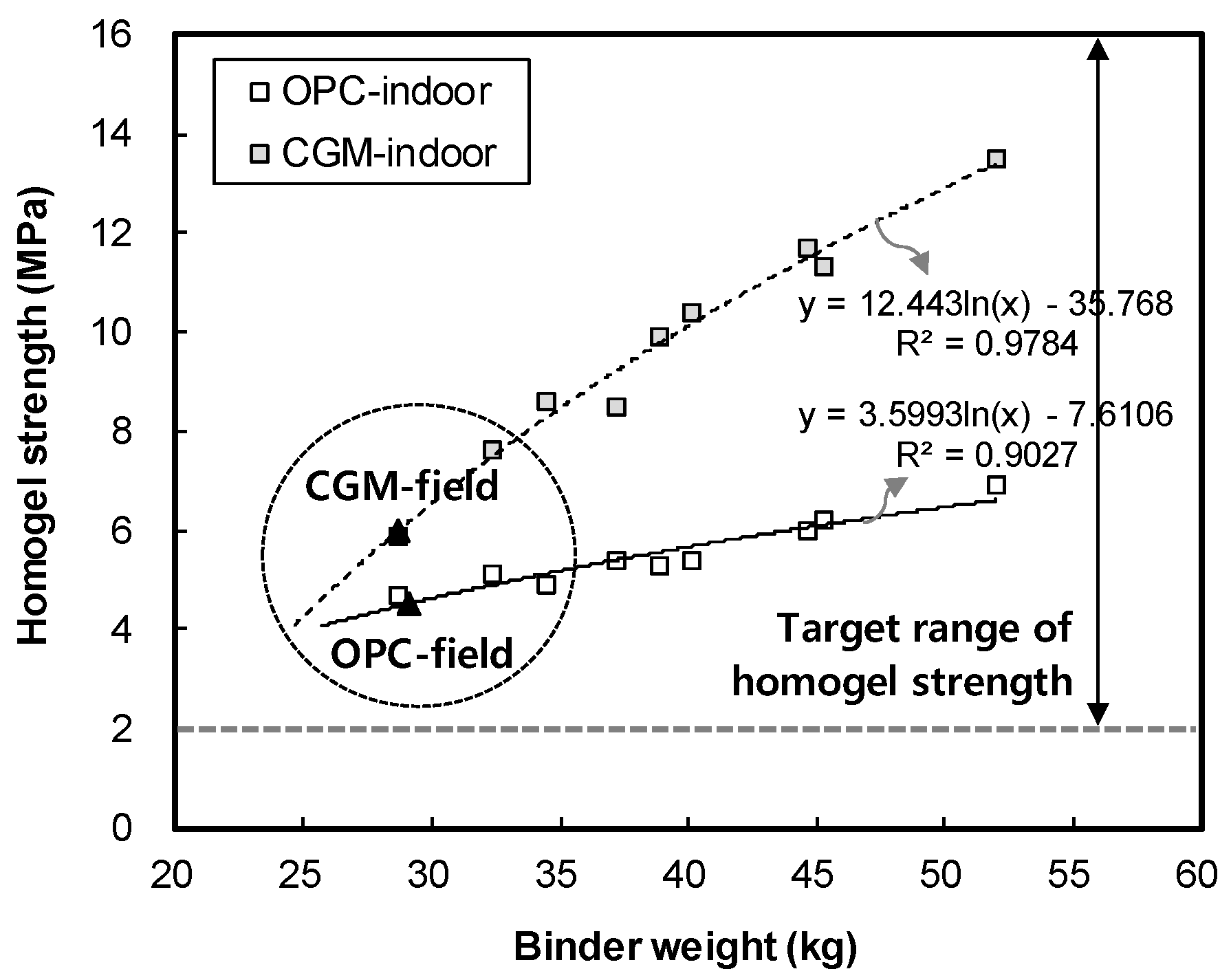
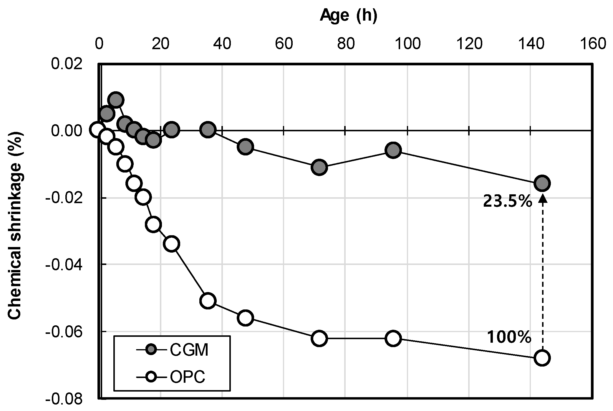
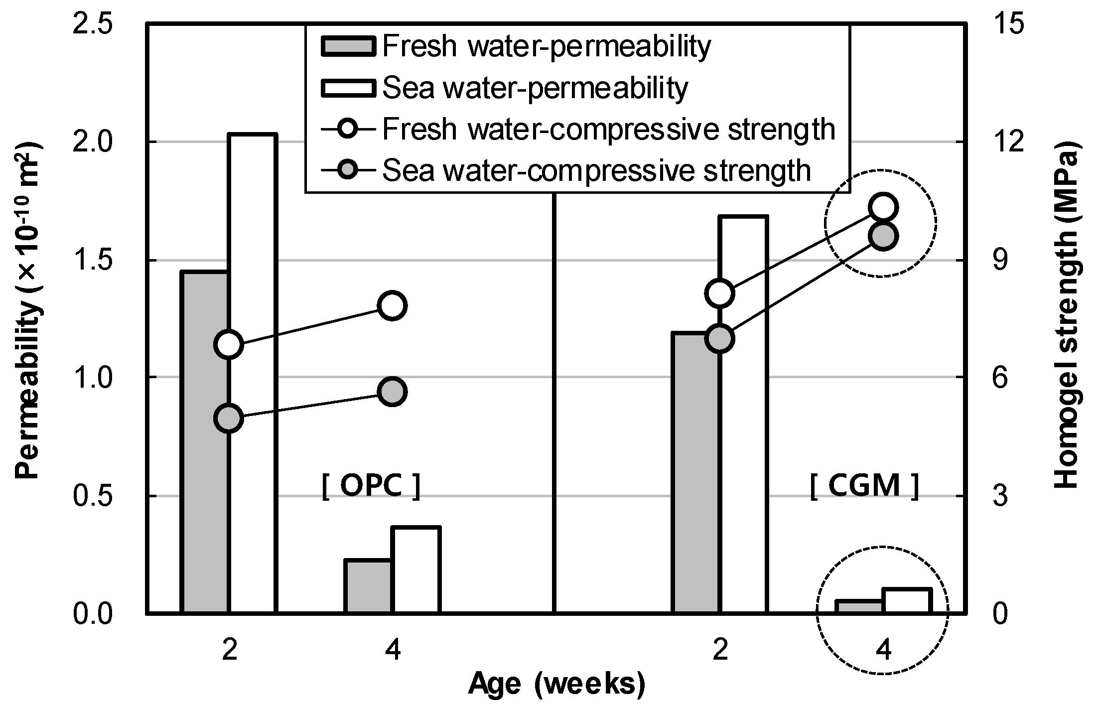
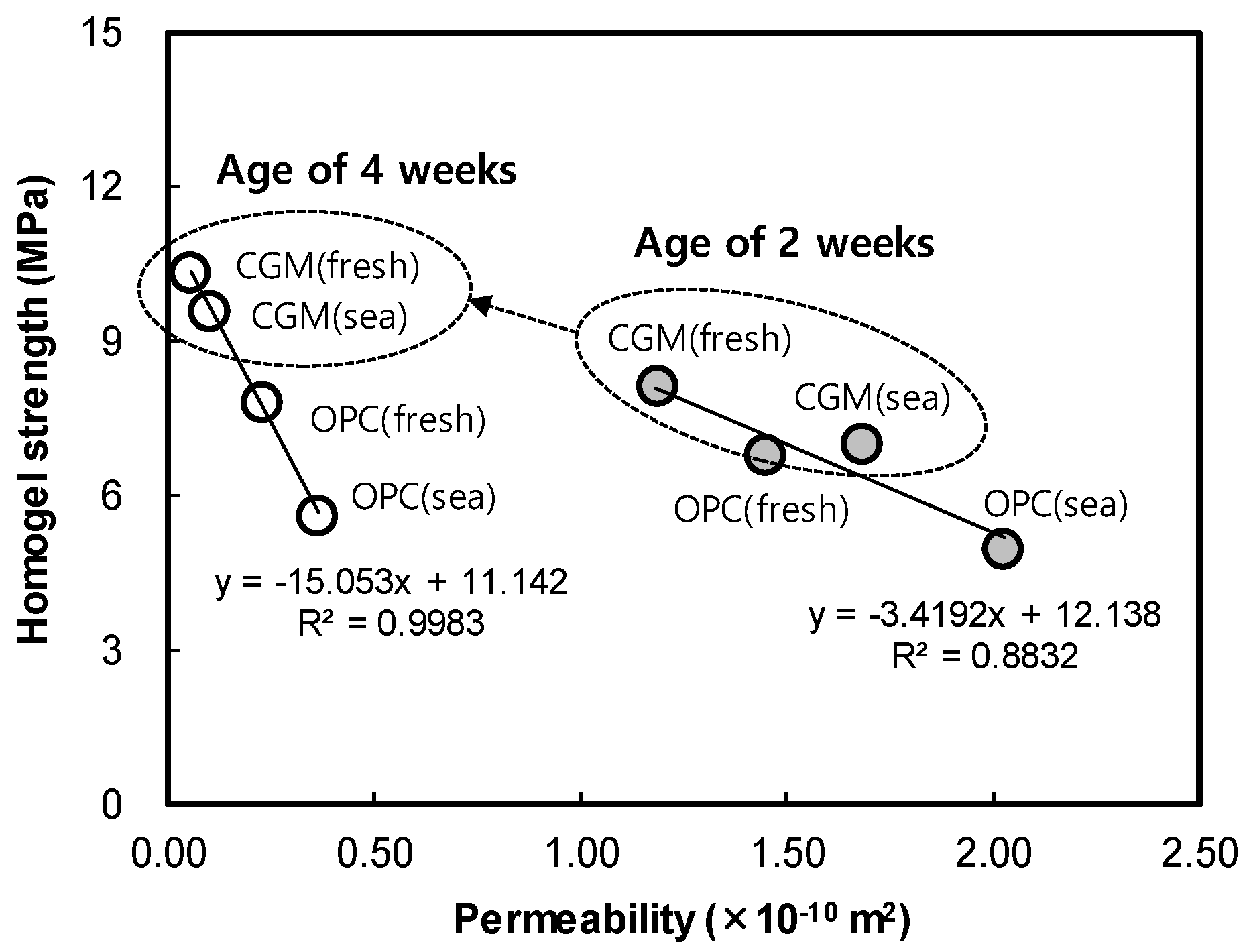
3.2. Effects of CGM on Increasing Homogel Strength
4. Conclusions
Author Contributions
Funding
Acknowledgments
Conflicts of Interest
References
- Chun, B.; Do, J.; Sung, H.; Lim, J. A study on the reinforcement and environmental impact of LW Injection. J. Korean Geoenviron. Soc. 2006, 7, 121–131. [Google Scholar]
- Axelsson, M.; Gustafson, G.; Fransson, A. Stop mechanism for cementitious grouts at different water-to-cement ratios. Tunn. Undergr. Space Technol. 2009, 24, 390–397. [Google Scholar] [CrossRef]
- Lee, S.W.; Kim, T.S.; Sim, B.K.; Kim, J.S.; Lee, I.M. Effect of pressurized grouting on pullout resistance and group efficiency of compression ground anchor. Can. Geotech. J. 2012, 49, 939–953. [Google Scholar] [CrossRef]
- Kroehong, W.; Sinsiri, T.; Jaturapitakkul, C.; Chindaprasirt, P. Effect of palm oil fuel ash fineness on the microstructure of blended cement paste. Constr. Build. Mater. 2011, 25, 4095–4104. [Google Scholar] [CrossRef]
- Choi, D. A Fundamental Study on the Response of the Concrete Industry to Climate Change; Eco-Friendly Concrete Committee of the Korea Concrete Institute: Seoul, Korea, 2009. [Google Scholar]
- Yi, Y.; Lu, K.; Liu, S.; Al-Tabbaa, A. Property changes of reactive magnesia–stabilized soil subjected to forced carbonation. Can. Geotech. J. 2015, 53, 314–325. [Google Scholar] [CrossRef]
- Lee, H. CO2 reduction technology for concrete. Mag. Korea Concr. Inst. 2011, 23, 28–31. [Google Scholar]
- Yi, Y.; Liska, M.; Unluer, C.; Al-Tabbaa, A. Carbonating magnesia for soil stabilization. Can. Geotech. J. 2013, 50, 899–905. [Google Scholar] [CrossRef]
- Phoo-ngernkham, T.; Chindaprasirt, P.; Sata, V.; Hanjitsuwan, S.; Hatanaka, S. The effect of adding nano-SiO2 and nano-Al2O3 on properties of high calcium fly ash geopolymer cured at ambient temperature. Mater. Des. 2014, 55, 58–65. [Google Scholar] [CrossRef]
- Guo, X.; Shi, H.; Dick, W.A. Compressive strength and microstructural characteristics of class C fly ash geopolymer. Cem. Concr. Compos. 2010, 32, 142–147. [Google Scholar] [CrossRef]
- Kim, J.W.; Lee, K.S.; Shin, S.W. A study on the development of an assessment methodology for emission from concrete manufacturing to CIP. J. Archit. Inst. Korea Plan. Des. 2011, 27, 103–110. [Google Scholar]
- Hu, S.; Wang, H.; Zhang, G.; Ding, Q. Bonding and abrasion resistance of geopolymeric repair material made with steel slag. Cem. Concr. Compos. 2008, 30, 239–244. [Google Scholar] [CrossRef]
- Pacheco-Torgal, F.; Castro-Gomes, J.P.; Jalali, S. Adhesion characterization of tungsten mine waste geopolymeric binder. Influence of OPC concrete substrate surface treatment. Constr. Build. Mater. 2008, 22, 154–161. [Google Scholar] [CrossRef]
- Woyciechowski, P.; Woliński, P.; Adamczewski, G. Prediction of carbonation progress in concrete containing calcareous fly ash co-binder. Materials 2019, 12, 2665. [Google Scholar] [CrossRef] [PubMed]
- Motorwala, A.; Shah, V.; Kammula, R.; Nannapaneni, P.; Raijiwala, P.D.B. Alkali activated fly-ash based geopolymer concrete. Int. J. Emerg. Technol. Adv. Eng. 2013, 3, 159–166. [Google Scholar]
- Bilim, C.; Atiş, C.D. Alkali activation of mortars containing different replacement levels of ground granulated blast furnace slag. Constr. Build. Mater. 2012, 28, 708–712. [Google Scholar] [CrossRef]
- Puertas, F.; Martínez-Ramírez, S.; Alonso, S.; Vazquez, T. Alkali-activated fly ash/slag cements: Strength behaviour and hydration products. Cem. Concr. Res. 2000, 30, 1625–1632. [Google Scholar] [CrossRef]
- Chindaprasirt, P.; Rattanasak, U. Utilization of blended fluidized bed combustion (FBC) ash and pulverized coal combustion (PCC) fly ash in geopolymer. Waste Manag. 2010, 30, 667–672. [Google Scholar] [CrossRef]
- Jang, J.G.; Park, S.M.; Chung, S.; Ahn, J.W.; Kim, H.K. Utilization of circulating fluidized bed combustion ash in producing controlled low-strength materials with cement or sodium carbonate as activator. Constr. Build. Mater. 2018, 159, 642–651. [Google Scholar] [CrossRef]
- Lin, W.T.; Weng, T.L.; Cheng, A.; Chao, S.J.; Hsu, H.M. Properties of controlled low strength material with circulating fluidized bed combustion ash and recycled aggregates. Materials 2018, 11, 715. [Google Scholar] [CrossRef]
- Sheng, G.; Li, Q.; Zhai, J.; Li, F. Self-cementitious properties of fly ashes from CFBC boilers co-firing coal and high-sulphur petroleum coke. Cem. Concr. Res. 2007, 37, 871–876. [Google Scholar] [CrossRef]
- Dung, N.T.; Chang, T.P.; Chen, C.T. Engineering and sulfate resistance properties of slag-CFBC fly ash paste and mortar. Constr. Build. Mater. 2014, 63, 40–48. [Google Scholar] [CrossRef]
- Li, X.G.; Chen, Q.B.; Ma, B.G.; Huang, J.; Jian, S.W.; Wu, B. Utilization of modified CFBC desulfurization ash as an admixture in blended cements: Physico-mechanical and hydration characteristics. Fuel 2012, 102, 674–680. [Google Scholar] [CrossRef]
- Sheng, G.; Zhai, J.; Li, Q.; Li, F. Utilization of fly ash coming from a CFBC boiler co-firing coal and petroleum coke in Portland cement. Fuel 2007, 86, 2625–2631. [Google Scholar] [CrossRef]
- Lee, J.H.; Kim, G.Y.; Kim, Y.R.; Mun, K.J.; Nam, J.S. Engineering properties and optimal conditions of cementless grouting materials. Materials 2019, 12, 3059. [Google Scholar] [CrossRef] [PubMed]
- Kim, Y.S.; Seo, S.G.; Ko, H.W.; Kim, J. Implementation of porous material through eco-tech for deep cement–soil mixing. Mar. Georesour. Geotechnol. 2018, 36, 931–939. [Google Scholar] [CrossRef]
- Češnovar, M.; Traven, K.; Horvat, B.; Ducman, V. The potential of ladle slag and electric arc furnace slag use in synthesizing alkali activated materials; the influence of curing on mechanical properties. Materials 2019, 12, 1173. [Google Scholar] [CrossRef]
- Mun, K.J. Development of non-cement material using recycled resources. Korea Inst. Build. Constr. 2014, 27, 156–157. [Google Scholar]
- Cheon, B.S. A Study on the Soft Ground Stabilization Method by Using High-Performance Grout; National Research Foundation of Korea: Seoul, Korea, 2002. [Google Scholar]
- Yang, H.C. Grouting Environmental Engineering; Goomiseogwan: Seoul, Korea, 2012. (In Korean) [Google Scholar]
- Sun, J. Project Specification of Grouting Method; Seoul Metro: Seoul, Korea, 2007. (In Korean) [Google Scholar]
- American Society for Testing and Materials. ASTM C109/C109M Standard Test Method for Compressive Strengthof Hydraulic Cement Mortars; ASTM: West Conshohocken, PA, USA, 1999. [Google Scholar]
- Korean Industrial Standards. KS L 3317 Testing Method for Permeability to Gases of Refractory Products; Korean Agency for Technology and Standards: Eumseong-gun, Korea, 2018.
- American Society for Testing and Materials. ASTM C1608-17 Standard Test Method for Chemical Shrinkage of hydraulic Cement Paste; ASTM: West Conshohocken, PA, USA, 2017. [Google Scholar]


| Materials | Chemical Composition (%) | Density (g/cm3) | pH (at 25 °C) | Viscosity (at 25 °C, Pa·s) | ||||
|---|---|---|---|---|---|---|---|---|
| H2O | SiO2 | Na2O | Fe2O3 | WI(1) | ||||
| SS (No. 3) | 63.6 | 27.2 | 9.14 | 0.0034 | 0.0026 | 1.384 | 14 | 0.2 |
| Materials | Chemical Composition (%) | Density (g/cm3) | Fineness (cm2/g) | ||||||
|---|---|---|---|---|---|---|---|---|---|
| SiO2 | Al2O3 | Fe2O3 | CaO | MgO | SO3 | Other | |||
| OPC | 17.20 | 4.38 | 3.13 | 66.70 | 3.03 | 3.48 | 2.08 | 3.15 | 3,120 |
| CGM | 17.60 | 7.01 | 0.52 | 58.85 | 2.02 | 12.73 | 1.27 | 2.89 | 4,190 |
| Evaluation Items | Experimental Variables | ||
|---|---|---|---|
| Factors of mixture | Types of liquid chemical | SS (No. 3) | |
| Types of liquid B binders | OPC, CGM | ||
| W/B ratio of liquid B | 140% | ||
| Volume replacement ratio of liquid B | 50% | ||
| Test items | Effects of CGM on shortening gel time | Gel state | Gel time (s) |
| Constructability | Average daily workload (m/day) | ||
| Construction speed | Construction period per 1 m (min/m) | ||
| Effects of CGM on increasing on homogel strength | Hardened state | Homogel strength (MPa) | |
| Durability | Chemical shrinkage (%) | ||
| Air permeability (×10−10 m2) | |||
| X-ray diffraction analysis | |||
| Scanning electron microscope analysis | |||
| Leakage length | Leakage length per 1 m2 (m/m2) | ||
| Mix No. | Liquid A | Liquid B | ||
|---|---|---|---|---|
| SS (No.3) (dm3) | Water (dm3) | Binders (dm3) | Water (dm3) | |
| OPC | 25 | 25 | 10 | 40 |
| CGM | 25 | 25 | 10 | 40 |
| Items | Contents |
|---|---|
| Project name | Knowledge industry center new construction |
| Structure system | Under ground floor: steel framed reinforced concrete (SRC) structure; ground floor: reinforced concrete (RC) structure |
| Land area | 19,486.00 m2 (5894.52 pyeong) |
| Construction area | 11,682.09 m2 (3533.83 pyeong) |
| Total floor area | 165,153.58 m2 (49,958.96 pyeong) |
| Total floor ratio | 445.30% |
| Building scale | 4 basement floors–10 floors/1 building/total of 938 rooms |
| Work period | 26 months |
| Binder Types | Serial Number of H-Pile | Sum of Cross Section Area |
|---|---|---|
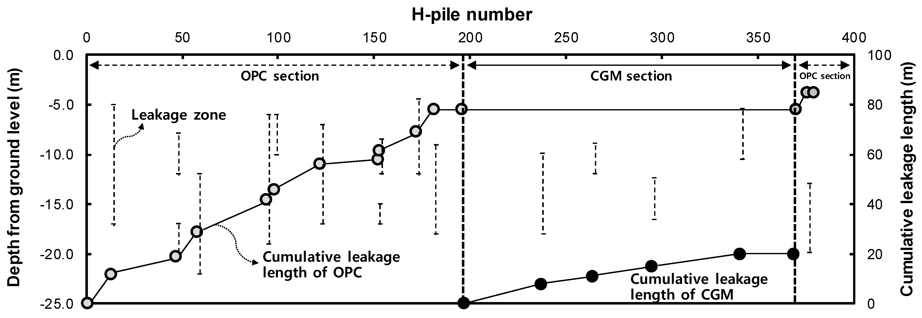
| OPC | 1–196, 370–379 | 6887 m2 |
| CGM | 197–369 | 6321 m2 |
| Items | Total Length(m) | Work Days (Days) | Average Daily Workload (m/Day) | Remarks |
|---|---|---|---|---|
| OPC | 13,913 | 95 | 146.5 | Measured based on 8 h/day (one machine, two workers) |
| CGM | 12,642 | 76 | 166.3 |
| Items | Total Length (m) | Construction Period (min) | Construction Period Per Meter (min/m) | Remarks |
|---|---|---|---|---|
| OPC | 13,913 | 45,600 | 3.28 | Measured based on 8 h/day (one machine, two workers) |
| CGM | 12,642 | 36,480 | 2.89 |
| Items | Area (m2) | Leakage Length (m) | Leakage Length Per 1 m2 (m/m2) | Remarks |
|---|---|---|---|---|
| OPC | 6887 | 85 | 0.012 | Measured based on the length of CIP leak section |
| CGM | 6321 | 20 | 0.003 |
© 2019 by the authors. Licensee MDPI, Basel, Switzerland. This article is an open access article distributed under the terms and conditions of the Creative Commons Attribution (CC BY) license (http://creativecommons.org/licenses/by/4.0/).
Share and Cite
Lee, J.; Lee, T. Effects of High CaO Fly Ash and Sulfate Activator as a Finer Binder for Cementless Grouting Material. Materials 2019, 12, 3664. https://doi.org/10.3390/ma12223664
Lee J, Lee T. Effects of High CaO Fly Ash and Sulfate Activator as a Finer Binder for Cementless Grouting Material. Materials. 2019; 12(22):3664. https://doi.org/10.3390/ma12223664
Chicago/Turabian StyleLee, Jaehyun, and Taegyu Lee. 2019. "Effects of High CaO Fly Ash and Sulfate Activator as a Finer Binder for Cementless Grouting Material" Materials 12, no. 22: 3664. https://doi.org/10.3390/ma12223664
APA StyleLee, J., & Lee, T. (2019). Effects of High CaO Fly Ash and Sulfate Activator as a Finer Binder for Cementless Grouting Material. Materials, 12(22), 3664. https://doi.org/10.3390/ma12223664