Analysis on the Effects of the Human Body on the Performance of Electro-Textile Antennas for Wearable Monitoring and Tracking Application


Abstract
1. Introduction
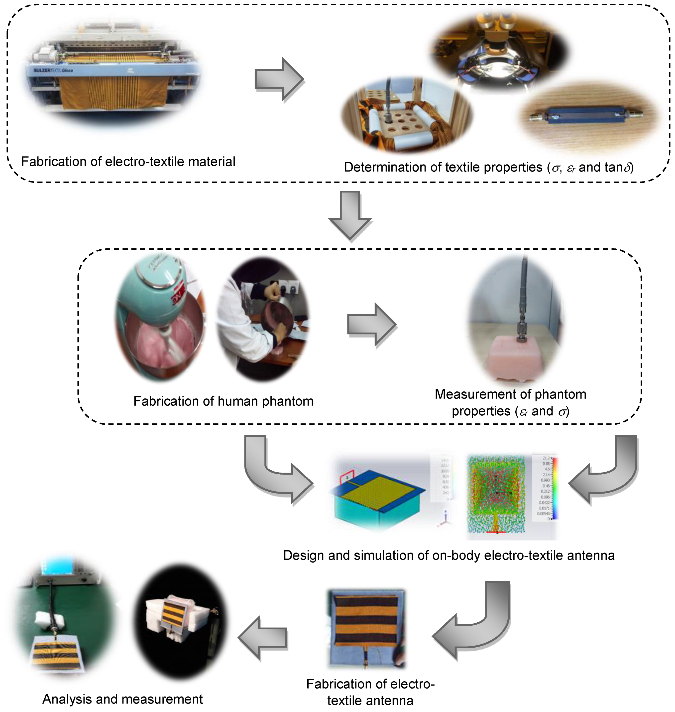
2. Methods and Processes
3. Characterization, Design and Fabrication of Wearable Antenna
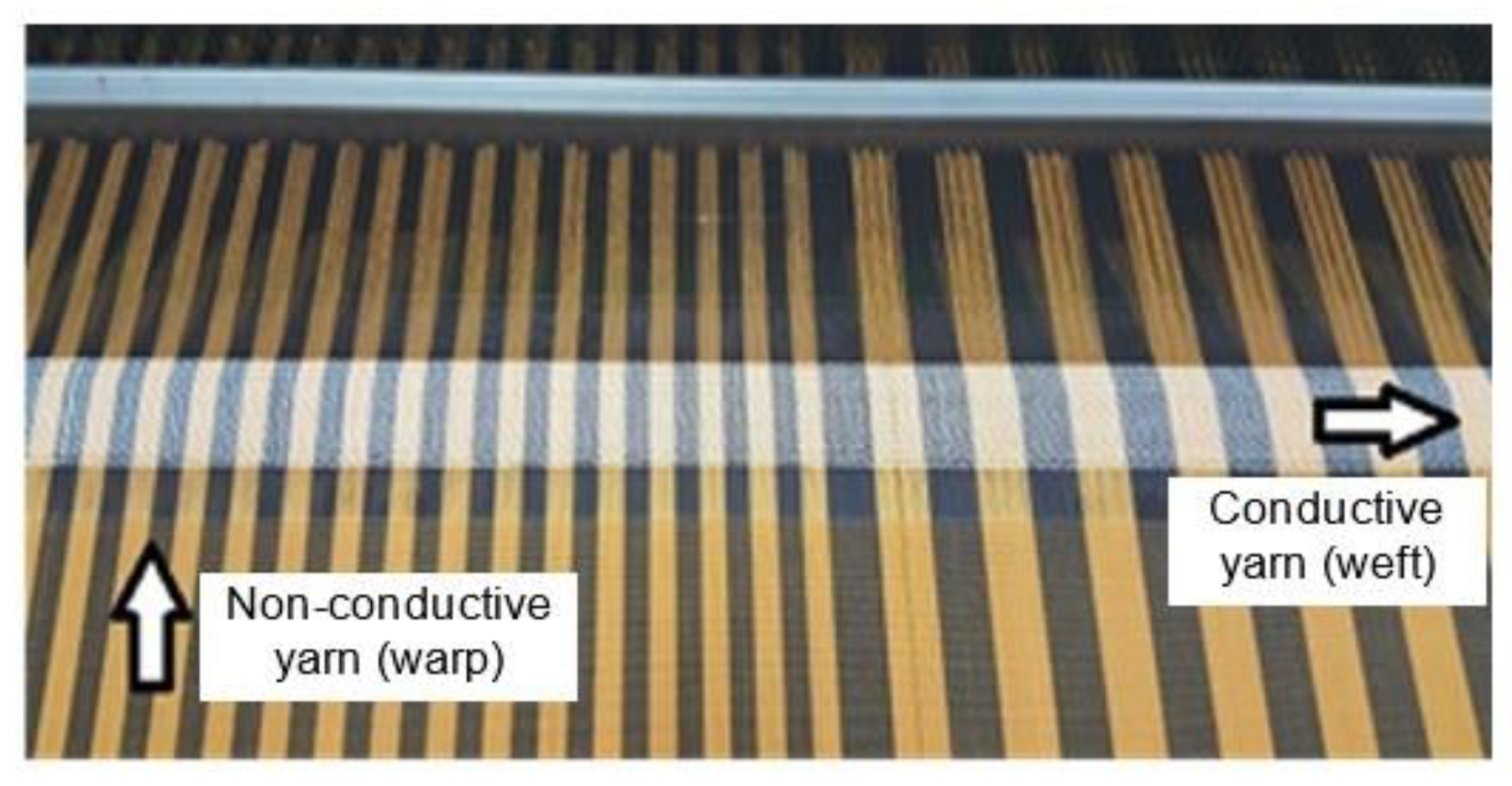
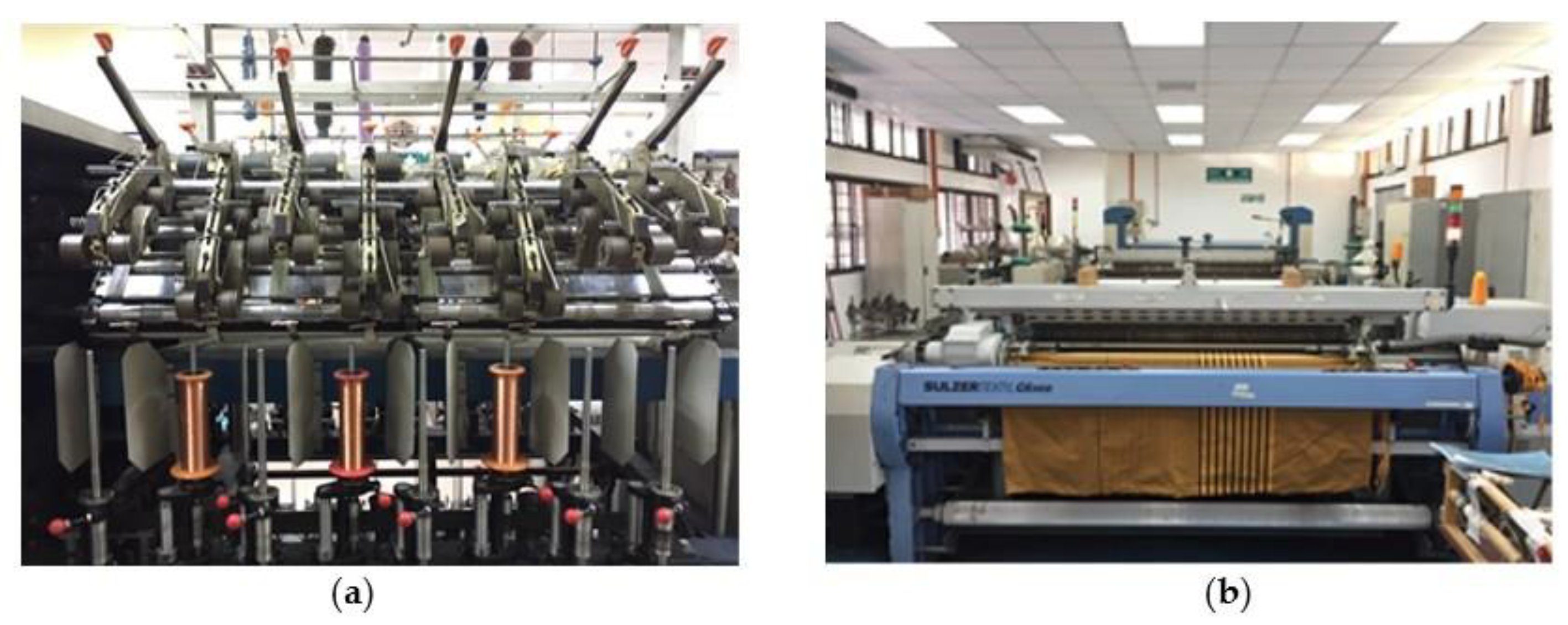
3.1. Electro-Textile Production
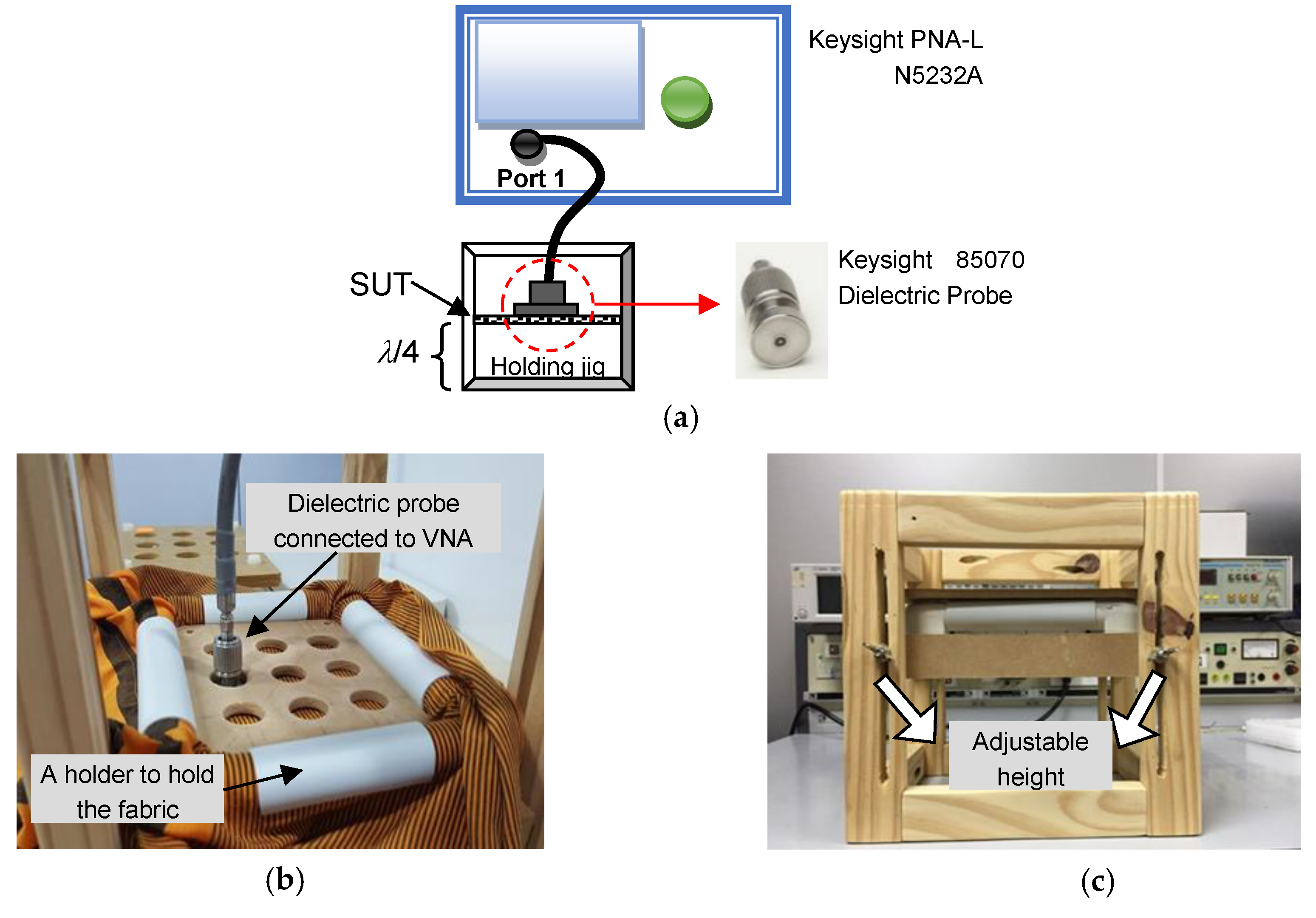
3.2. Electrical and Dielectric Properties
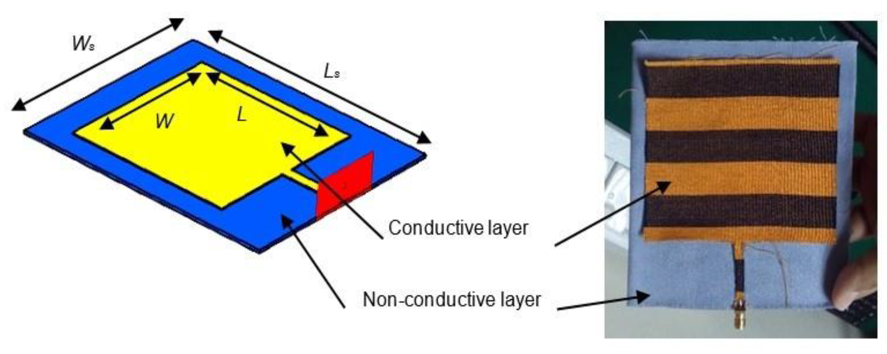
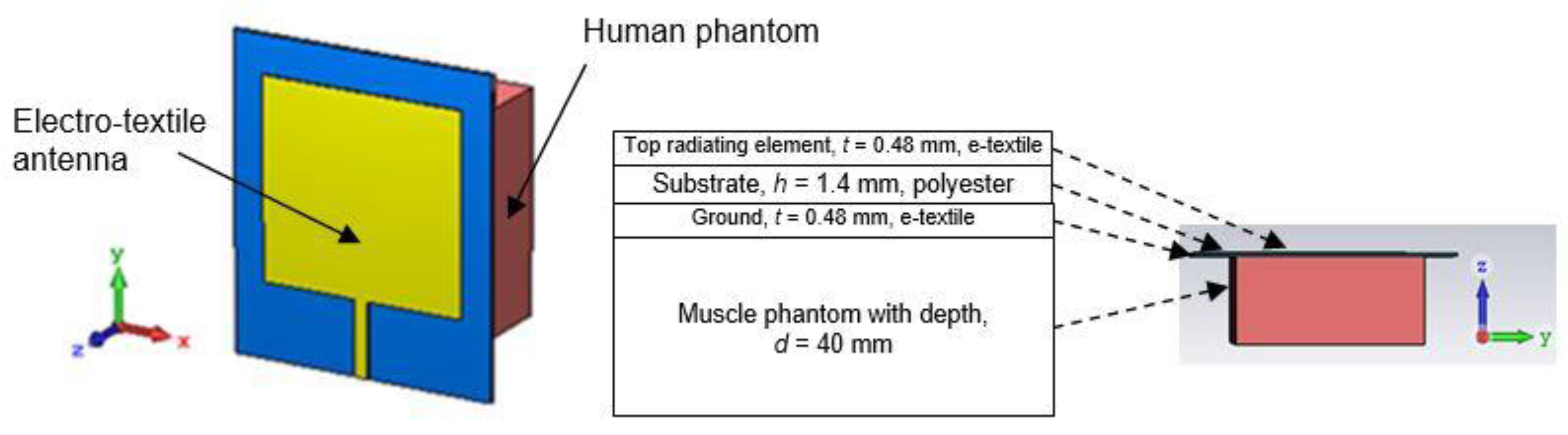
3.3. Antenna Design (Ideal and On-Body Conditions)
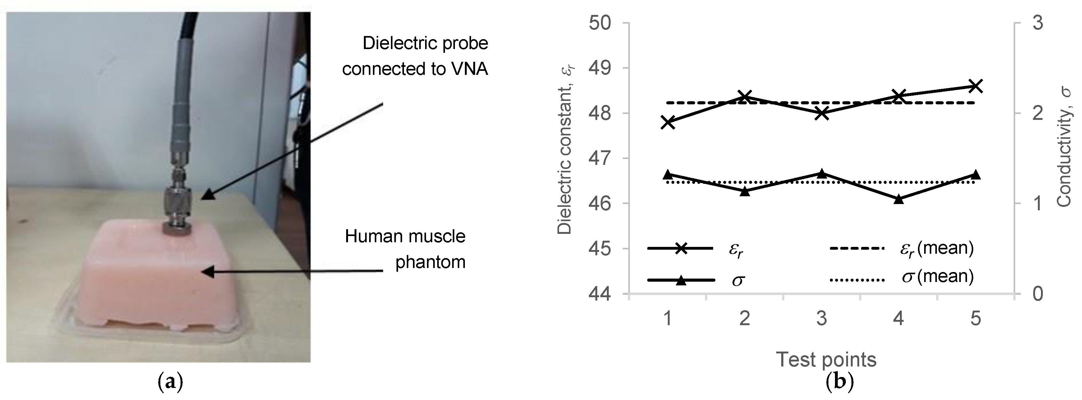
4. Fabrication of Human Muscle Phantom
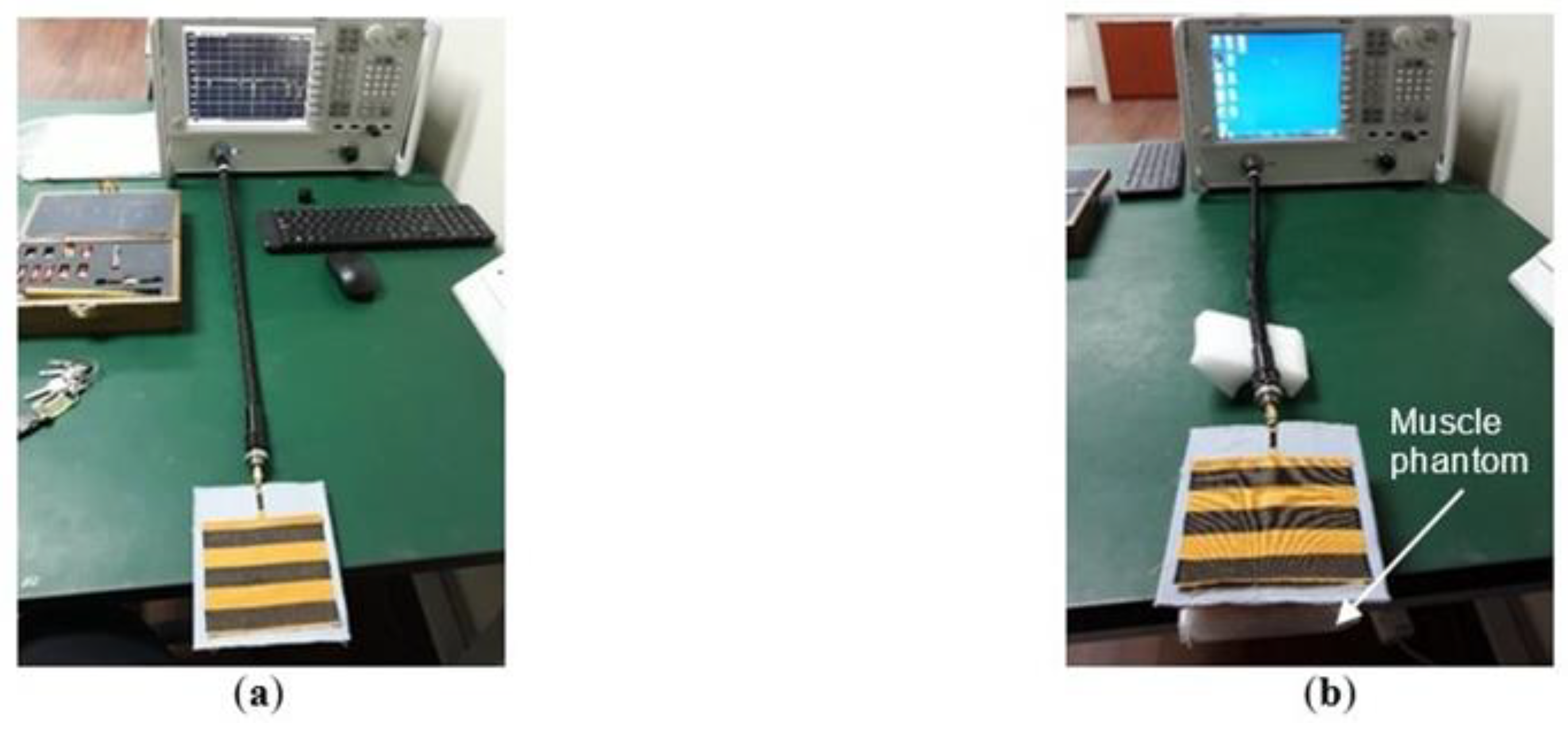
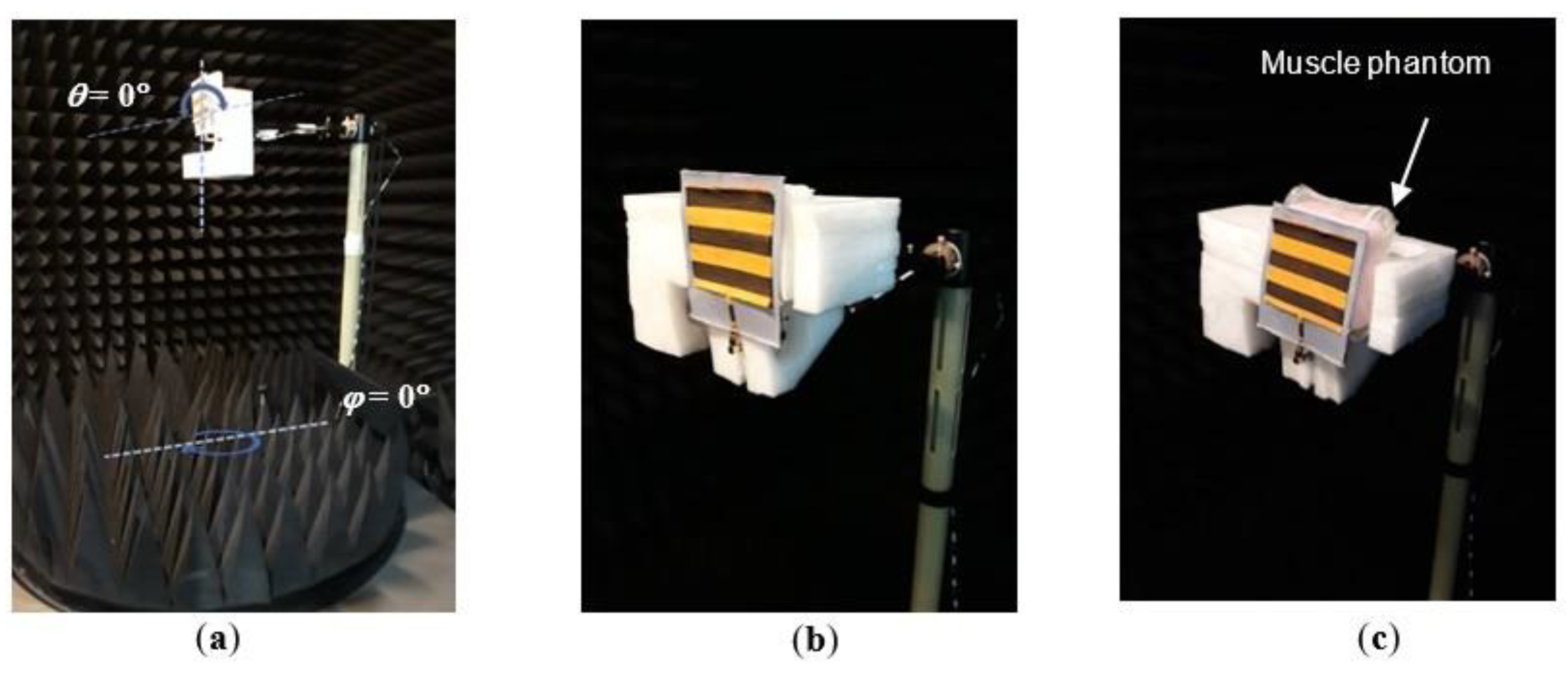
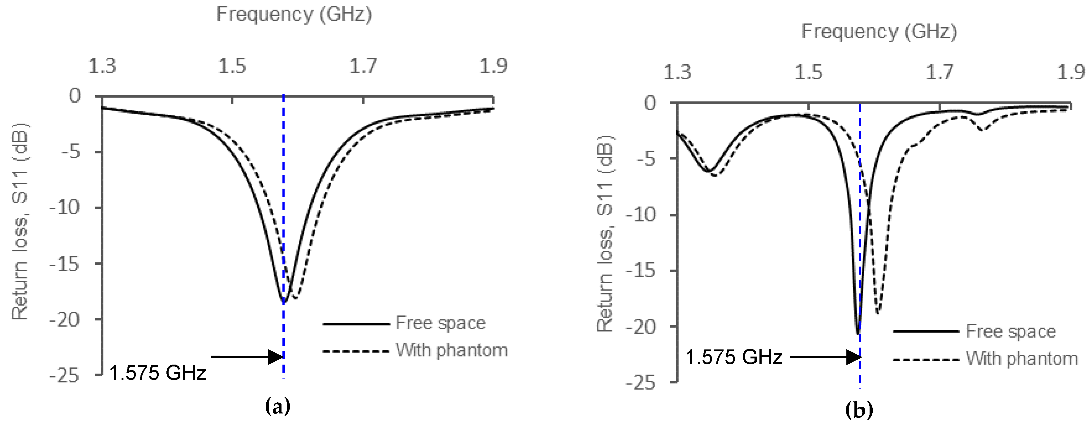
5. Results
6. Discussion and Analysis
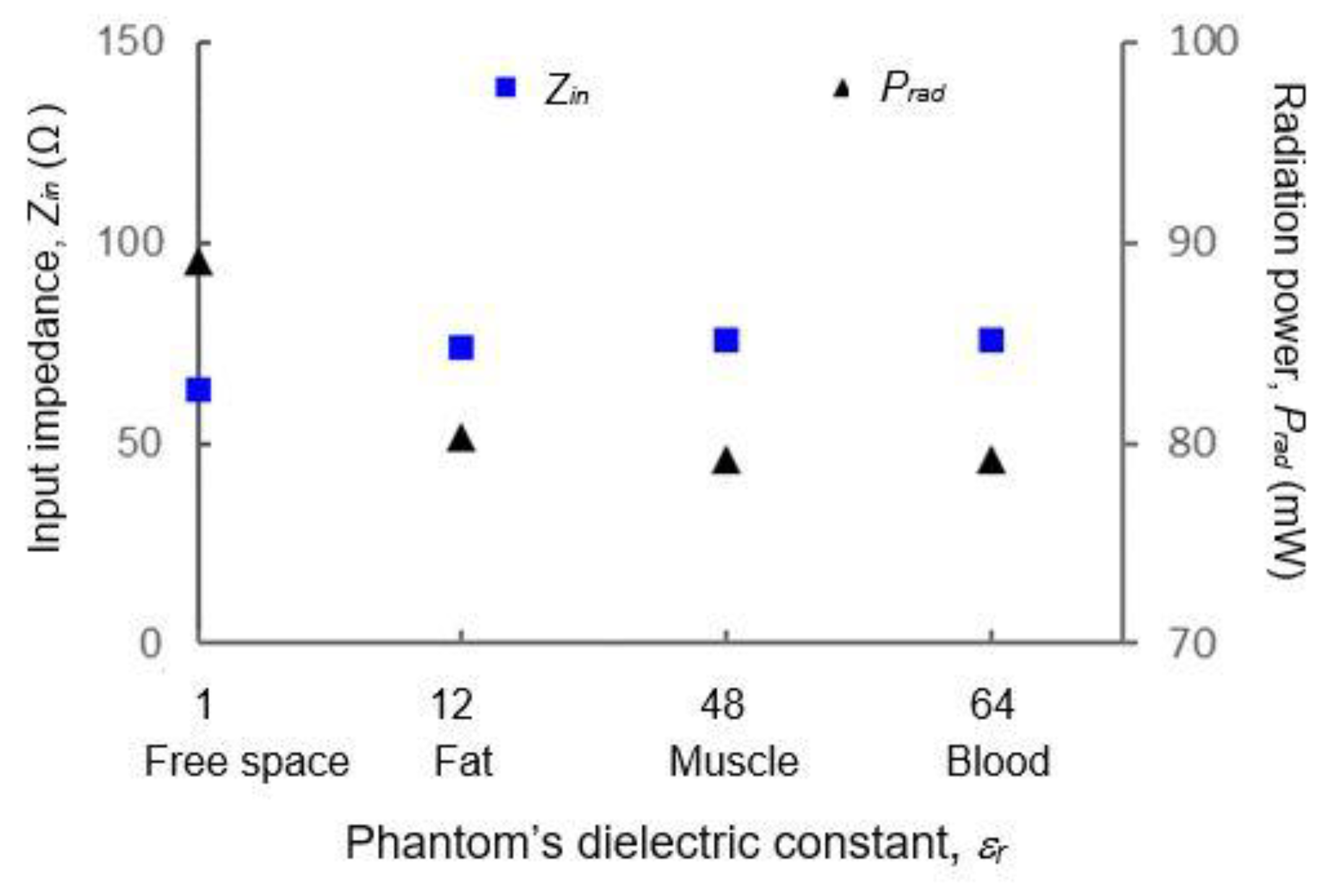
6.1. Correlation Between On-Body Condition with Input Impedance, Zin
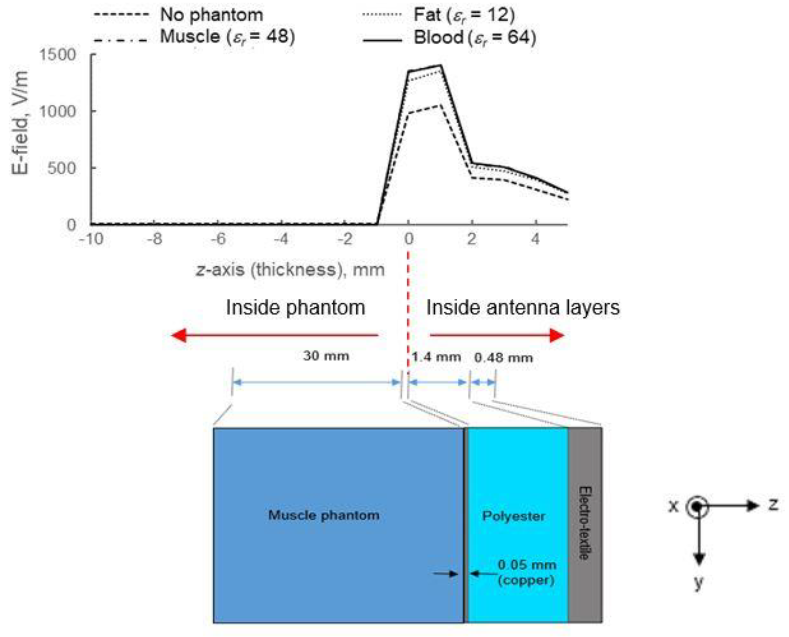
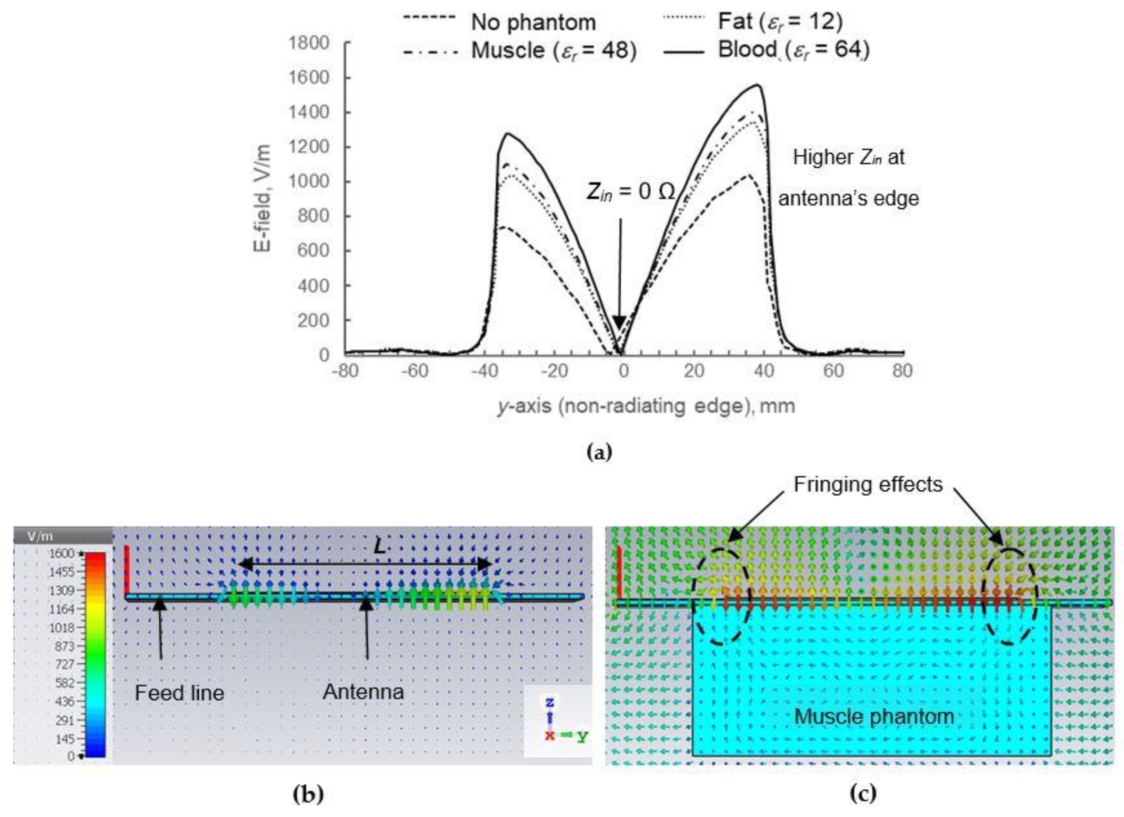
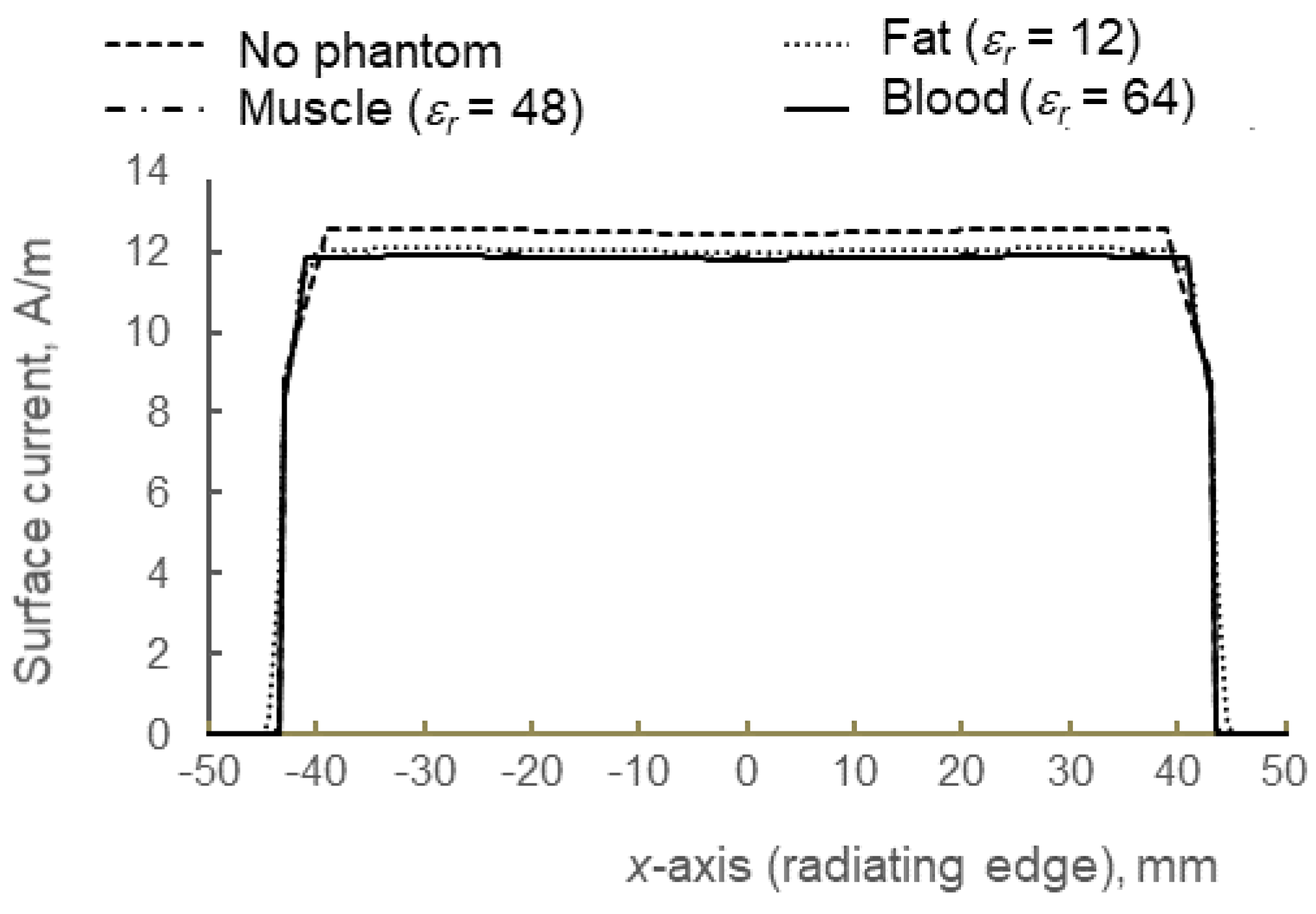
6.2. Correlation Between On-Body Condition with Near-Field Distribution
6.3. Scope and Limitations
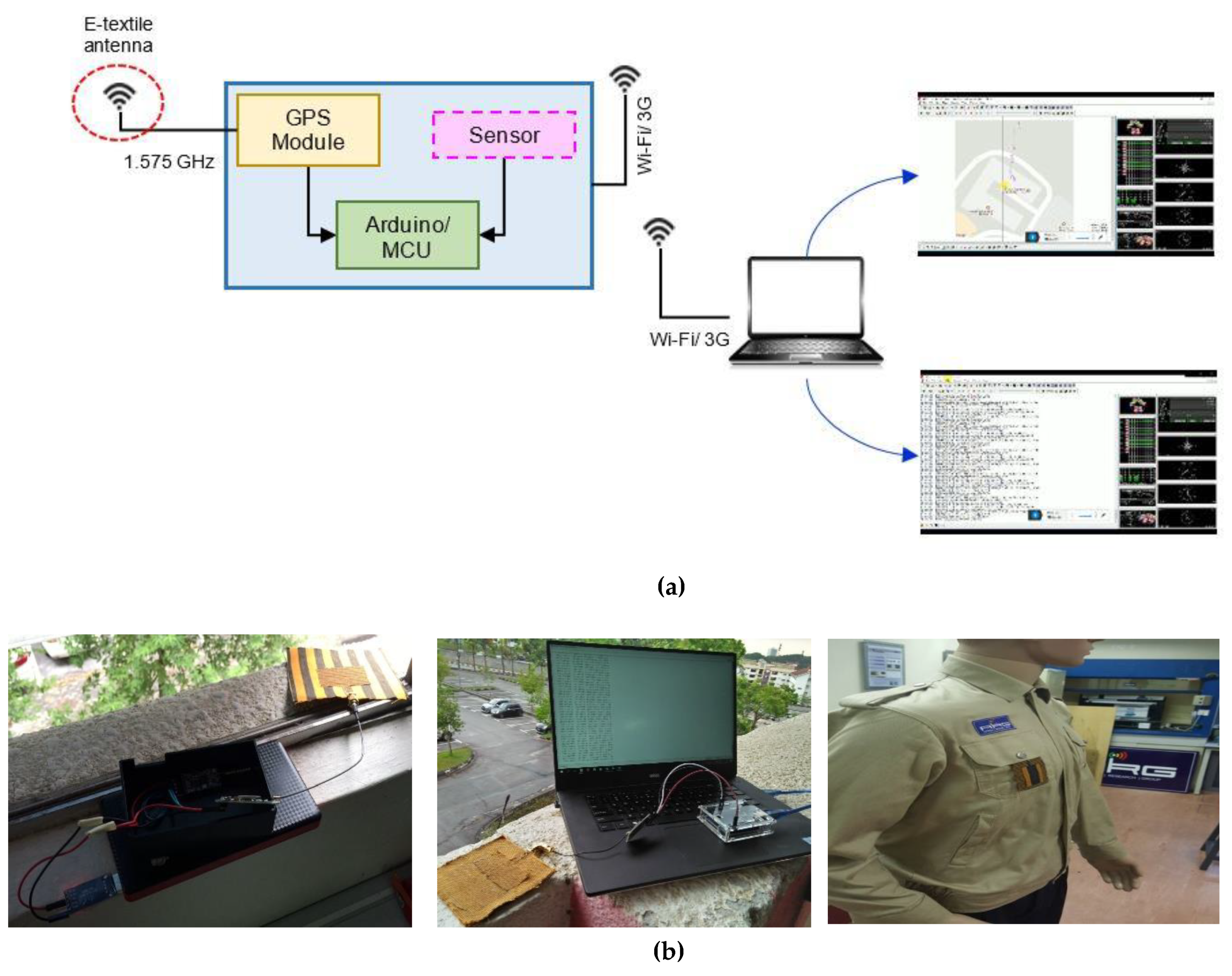
7. Integration with GPS Tracking Device
8. Conclusions
Author Contributions
Funding
Acknowledgments
Conflicts of Interest
References
- Wang, Z.; Zhang, L.; Volakis, J.L. Textile antennas for wearable radio frequency applications. TLIST 2013, 2, 105–112. [Google Scholar]
- Amendola, S.; Lodato, R.; Manzari, S.; Occhiuzzi, C.; Marrocco, G. RFID technology for IoT-based personal healthcare in smart spaces. IEEE Internet Things J. 2014, 1, 144–151. [Google Scholar] [CrossRef]
- Lee, H.; Tak, J.; Choi, J. Wearable antenna integrated into military berets for indoor/outdoor positioning system. IEEE Antennas Wirel. Propag. Lett. 2017, 16, 1919–1922. [Google Scholar] [CrossRef]
- Moradi, E.; Koski, K.; Bjorninen, T.; Sydanheimo, L.; Rabaey, J.M.; Carmena, J.M.; Rahmat-Samii, Y.; Ukkonen, L. Miniature implantable and wearable on-body antennas: Towards the new era of wireless body-centric systems. IEEE Antennas Propag. Mag. 2014, 56, 271–291. [Google Scholar]
- Yahya, R.; Kamarudin, M.R.; Seman, N. Effect of Rainwater and Seawater on the Permittivity of Denim Jean Substrate and Performance of UWB Eye-Shaped Antenna. IEEE Antennas Wirel. Propag. Lett. 2014, 13, 806–809. [Google Scholar] [CrossRef]
- Kiourti, A.; Volakis, J.L. Conductive textiles for wearable electronics. In Proceedings of the International Symposium on Electromagnetic Theory, Espoo, Finland, 14–18 August 2016; 2016; pp. 518–519. [Google Scholar]
- Haghi, M.; Thurow, K.; Stoll, R. Wearable devices in medical Internet of Things: Scientific research and commercially available devices. J Healthc Inform Res. 2017, 23, 4–15. [Google Scholar] [CrossRef] [PubMed]
- Ferreira, D.; Pires, P.; Rodrigues, R.; Caldeirinha, R.F.S. Wearable Textile Antennas: Examining the effect of bending on their performance. IEEE Antennas Propag. Mag. 2017, 59, 54–59. [Google Scholar] [CrossRef]
- Christina, G.; Rajeswari, A.; Lavanya, M.; Keerthana, J.; Ilamathi, K.; Manoranjitha, V. Design and development of wearable antennas for tele-medicine applications. In Proceedings of the IEEE International Conference on Communication and Signal Processing, Melmaruvathur, India, 6–8 April 2016; pp. 2033–2037. [Google Scholar]
- Lilja, J.; Salonen, P.; Kaija, T.; Maagt, P.D. Design and manufacturing of robust textile antennas for harsh environments. IEEE Trans. Antennas Propag. 2012, 60, 4130–4140. [Google Scholar] [CrossRef]
- Roshni, S.B.; Jayakrishnan, M.P.; Mohanan, P.; Surendran, K.P. Design and fabrication of an E-shaped wearable textile antenna on PVB-coated hydrophobic polyester fabric. Smart Mater. Struct. 2017, 26, 1–8. [Google Scholar] [CrossRef]
- Abd Rahman, N.H.; Yamada, Y.; Amin Nordin, M.S. Reliability of Strip Line Method for Determination of Conductivity for Lossy Conductive Materials. IEEE Access 2018, 6, 64630–64638. [Google Scholar] [CrossRef]
- Melia, G. Electromagnetic Absorption by the Human Body from 1–15 GHz. Ph.D Thesis, University of York, York, UK, August 2013. [Google Scholar]
- Seneviratne, S.; Hu, Y.; Nguyen, T.; Lan, G.; Khalifa, S.; Thilakarathna, K.; Hassan, M.; Seneviratne, A. A survey of wearable devices and challenges. IEEE Commun. Surv. Tutor. 2017, 19, 2573–2620. [Google Scholar] [CrossRef]
- Pinapati, S.P.; Chen, S.J.; Ranasinghe, D.; Fumeaux, C. Detuning effects of wearable patch antennas. In Proceedings of the Asia Pacific Microwave Conference, Kuala Lumpur, Malaysia, 13–16 November 2017; pp. 162–165. [Google Scholar]
- Soh, P.J.; Vandenbosch, G.A.E.; Ooi, S.L.; Rais, N.H.M. Design of a Broadband All-Textile Slotted PIFA. IEEE Trans. Antennas Propag. 2012, 60, 379–384. [Google Scholar] [CrossRef]
- Keshmiri, F. Body-Area-Network Antennas: Green’s Functions, Numerical Analysis and Design. Ph.D Thesis, Université Catholique de Louvain, Louvain-la-Neuve, Belgium, February 2012. [Google Scholar]
- Kellomaki, T. Effects of the Human Body on single layer wearable antennas. Ph.D Thesis, Tampere University of Technology, Tampere, Finland, March 2012. [Google Scholar]
- Chowdhury, S.R.; Ali, K. Effects of human body on antenna performance: A quantitative study. In Proceedings of the International Conference on Computer and Information Technology (ICCIT), Florence, Italy, 11–12 April 2016; IEEE: Dhaka, Bangladesh, 2016; pp. 108–112. [Google Scholar]
- Kumar, V.; Gupta, B. On-body measurements of SS-UWB patch antenna for WBAN applications. AEU-Int. J. Electron. Commun. 2016, 72, 184–191. [Google Scholar] [CrossRef]
- Fujita, K.; Yoshitomi, K.; Yoshida, K.; Kanaya, K. A circularly polarized planar antenna on flexible substrate for ultra-wideband high-band applications. AEU-Int. J. Electron. Commun. 2015, 69, 1381–1386. [Google Scholar] [CrossRef]
- Boyes, S.J.; Soh, P.J.; Huang, Y.; Vandenbosch, G.A.E.; Khiabani, N. Measurement and performance of textile antenna efficiency on a human body in a reverberation chamber. IEEE Trans. Antennas Propag. 2013, 61, 871–881. [Google Scholar] [CrossRef]
- Abdullah, A.S.; Ahmed, A.G.; Nikolay, D.; Nikolay, A. On-body investigation of a compact planar antenna on multilayer polymer composite for body-centric wireless communications. AEU-Int. J. Electron. Commun. 2017, 82, 20–29. [Google Scholar]
- Heaney, M.B. Electrical Conductivity and Resistivity. In Electrical Measurement, Signal Processing, and Displays; Webster, J.G., Ed.; CRC Press: Boca Raton, FL, USA, 2003; pp. 7–11. [Google Scholar]
- ASTM D3776—Standard test methods for mass per unit area (weight) of fabric; ASTM International: West Conshohocken, PA, USA, 2009.
- Keysight Technologies, Basics of Measuring the Dielectric Properties of Materials—Application Note, 2017. Available online: http://literature.cdn.keysight.com/litweb/pdf/5989-2589EN.pdf (accessed on 2 January 2019).
- Hasgall, P.A.; Gennaro, F.D.; Baumgartner, C.; Neufeld, E.; Lloyd, B.; Gosselin, M.C.; Payne, D.; Klingenböck, A.; Kuster, N. Data from: IT’IS database for thermal and electromagnetic parameters of biological tissues V4 [Dataset]; IT’IS Foundation: Zurich, Switzerland, 2018; Available online: https://doi.org/10.13099/VIP21000-04-0 (accessed on 28 December 2018).
- Cavallari, R.; Martelli, F.; Rosini, R.; Buratti, C.; Verdone, R. A Survey on Wireless Body Area Networks: Technologies and Design Challenges. IEEE Commun. Surv. Tutor. 2014, 16, 1635–1657. [Google Scholar] [CrossRef]


| Properties | Values |
|---|---|
| Conductivity (σ) | 2.2 × 10⁴ S/m |
| Thickness (t) | 0.48 mm |
| Fabric composition | 83% Copper + 17% Polyester |
| Ingredients | Purpose | Quantity |
|---|---|---|
| Deionized water | Main component | 420 mL |
| Agar | Polyethylene powder | 20 g |
| Sodium dehydroacetate | As a preservative | 0.25 g |
| Xanthan gum | As a thickener | 6.25 g |
| Sodium chloride (NaCl) | To control the σ of phantom | 4.1 g |
| Polyethylene powder | To control the εr of phantom | 29 g |
| Condition | Fat (εr = 12) | Muscle (εr = 48) | Blood (εr = 64) |
|---|---|---|---|
| Detuning % | 1.14 | 1.4 | 1.4 |
| ΔZin (%) | 17 ↑ | 19 ↑ | 20 ↑ |
| ΔPrad (%) | 9 ↓ | 11 ↓ | 11 ↓ |
| ΔE-field intensity (%) | 29.7 ↑ | 35.3 ↑ | 36.1 ↑ |
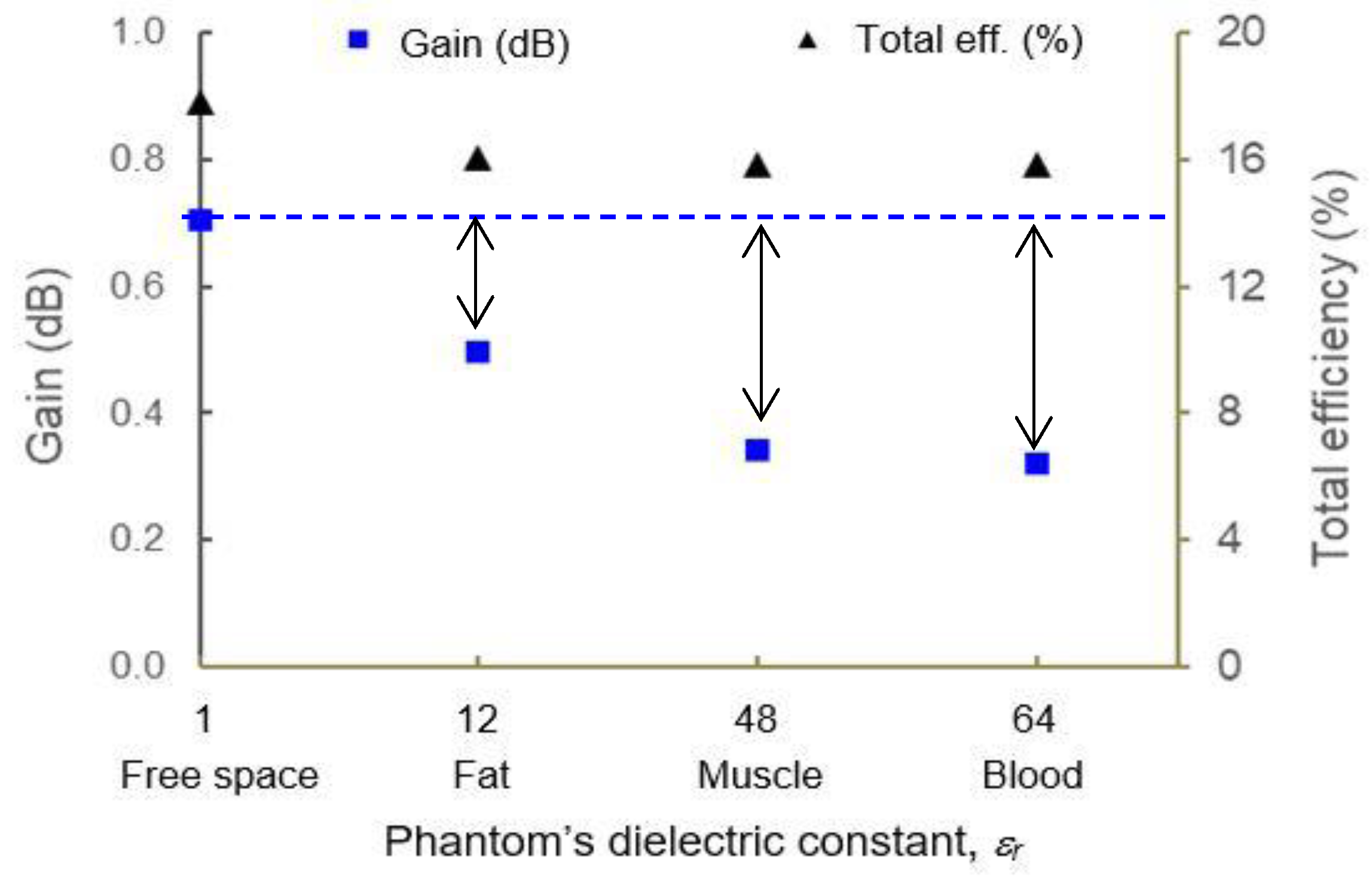
| ΔTotal efficiency % | 1.74 ↓ | 2 ↓ | 2 ↓ |
| ΔGain (dB) | 0.21 ↓ | 0.37 ↓ | 0.39 ↓ |
© 2019 by the authors. Licensee MDPI, Basel, Switzerland. This article is an open access article distributed under the terms and conditions of the Creative Commons Attribution (CC BY) license (http://creativecommons.org/licenses/by/4.0/).
Share and Cite
Abd Rahman, N.H.; Yamada, Y.; Amin Nordin, M.S. Analysis on the Effects of the Human Body on the Performance of Electro-Textile Antennas for Wearable Monitoring and Tracking Application. Materials 2019, 12, 1636. https://doi.org/10.3390/ma12101636
Abd Rahman NH, Yamada Y, Amin Nordin MS. Analysis on the Effects of the Human Body on the Performance of Electro-Textile Antennas for Wearable Monitoring and Tracking Application. Materials. 2019; 12(10):1636. https://doi.org/10.3390/ma12101636
Chicago/Turabian StyleAbd Rahman, Nurul Huda, Yoshihide Yamada, and Muhammad Shakir Amin Nordin. 2019. "Analysis on the Effects of the Human Body on the Performance of Electro-Textile Antennas for Wearable Monitoring and Tracking Application" Materials 12, no. 10: 1636. https://doi.org/10.3390/ma12101636
APA StyleAbd Rahman, N. H., Yamada, Y., & Amin Nordin, M. S. (2019). Analysis on the Effects of the Human Body on the Performance of Electro-Textile Antennas for Wearable Monitoring and Tracking Application. Materials, 12(10), 1636. https://doi.org/10.3390/ma12101636