Abstract
In this paper, experimental and numerical analyses are performed with a Rapid Compression and Expansion Machine (RCEM) equipped with a passive pre-chamber (PC) and fueled with premixed stoichiometric air/methane mixture to replicate engine-like conditions. The main objective of this work is to study the effects of PC geometry, initial charge conditions and hydrogen addition to methane on combustion and flame extinction. From the experiments at different PC geometries, the combustion images acquired with a high-speed camera show the existence of a critical PC configuration (Long φ4) exhibiting the highest flame extinction probability (~54% under baseline conditions). The increase in the initial charge pressure and/or the enrichment of the methane with hydrogen (up to 30% H2 by volume) help to mitigate the flame extinction by reducing its probability to about 10%. Subsequently, a 0D RCEM model is developed (GT-PowerTM) and enhanced with user sub-models of turbulent combustion and flame quenching. Once tuned, the model reproduces the impact of PC design, higher initial gas pressure and hydrogen enrichment on the combustion evolution. The quenching sub-model, calibrated for the side wall quenching configuration, is able to forecast the experimental flame extinction tendency for the critical PC by modifying the hydrogen enrichment or initial gas pressure. The proposed methodology, describing the flame extinction tendency in PC combustion systems through 0D quenching modeling, represents the novel aspect for PC-equipped devices aiming to support their study and supplement engine investigations during the development phase.
1. Introduction
Worldwide legislators have been imposing increasing restrictions over the years for the homologation of new vehicles with the aim of facing the issues related to global environmental pollution deriving from greenhouse gas (GHG) emissions. In this context, the transportation sector represents one of the major contributors to global GHG emissions. Indeed, in the European region, road transport vehicles are responsible for 72% of total CO2 emissions [1]. To overcome these concerns, both the manufacturers and the scientific community are directing many efforts toward developing innovative propulsion systems characterized by high efficiency and low environmental impact. On the other hand, considerable attention is being paid to the employment of clean fuels (such as low carbon and/or carbon-free fuels) [2]. Among the different options, E-fuels, including hydrogen, seem to be particularly attractive as substitutes for traditional fossil fuels in internal combustion engines (ICEs) for future sustainable mobility [3,4]. Hydrogen is gaining increasing interest thanks to its physical properties, such as high energy per unit mass, enhanced mixing with air due to high diffusivity and fast flame propagation over a wide range of pressure, temperature and equivalence ratios. On the other hand, hydrogen shows preferential diffusion effects due to a low Lewis number (Le < 1) promoting thermo-diffusive instabilities, altering the flame structure and requiring advanced combustion modeling [5].
Nevertheless, in the short/medium-term scenario, the low-carbon fuels such as methane and renewable fuels (i.e., bio-methane) will represent very promising solutions to achieve an effective reduction in CO2 and noxious species emitted by internal combustion engines for vehicle applications [6].
Although methane is recognized as a favorable fuel for ICEs, it shows the main drawback of poor combustion properties such as low chemical reactivity and laminar flame speed [7]. The latter characteristic penalizes the flame propagation in conventional Spark Ignition (SI) units, often leading to the use of blends with low/moderate hydrogen contents [8], system re-design to promote turbulence improvement [9] and the adoption of innovative combustion modes [10,11]. In particular, turbulent jet ignition (TJI) is gaining considerable attention as an advanced combustion concept due to the capability to highly enhance the combustion speed in the main chamber (MC) thanks to the distributed ignition sites and the increased turbulence deriving from hot jets ejected by the PC toward the MC [12]. An important aspect of research for PC combustion systems is the investigation of flame behavior, including the extinctions of PC flame jets. These phenomena can lead to delayed combustions or even misfiring since flame jets are responsible for the ignition of the air/fuel mixture in the main chamber and their failure results in an unignited or poorly ignited mixture [13]. Therefore, the understanding of flame characteristics in PC devices is a key factor to achieve regular combustions, high efficiency and low emissions from the TJI technique [14]. Different experimental facilities have been used by researchers to study the flame characteristics of PC combustion systems, including constant volume or pressure combustion chambers, optical accessible single-cylinder engines, pressurized burned rings and Rapid Compression Machines (RCMs)/Rapid Compression and Expansion Machines (RCEMs).
Among the above test facilities, the RCEM is a “single-shot” device capable of rapidly compressing a premixed air/fuel charge with the aim of initiating ignition–combustion processes and then quickly expanding the exhaust gases. It is very useful to reproduce realistic operating conditions of ICEs while ensuring a highly controllable environment, repeatability of tests and optical accessibility. For these reasons, RCEMs have been used to perform a wide variety of investigations, such as measurements of ignition delay time, flame kernel development, knock, pre-ignition and emission formation mechanisms, spray studies, flame extinctions, etc. As already mentioned, they have shown their potential in analyzing the ignition mechanism promoted by PC jets and in identifying the conditions where the PC flame jets are most prone to extinction due to quenching. The technical literature reports some articles investigating the turbulent jet ignition process and the quenching at the PC nozzle exit using the RCM/RCEM by means of both experimental and numerical methods. As an example, Xu et al. [15] conducted flame analyses of lean air/methane mixtures on an RCEM test ring to better understand the jet formation process in a passive PC, deepening the effects of jet characteristics on subsequent MC combustion. The results from optical diagnostics (high-speed OH*- chemiluminescence and Schlieren imaging) are used to validate a 3D RANS CFD model employing the G-equation and specific sub-models of ignition and flame–wall interaction phenomena occurring in PC. Combined insights from experiments and CFD calculations suggest that the early phase of jet exit from the PC is the most critical one, and global flame quenching is most likely to occur in this period. Allison et al. [16] studied the jet ejection process using high-speed imaging (OH* and CH* chemiluminescence) and Large-Eddy simulation (LES) to observe the composition and the temporal development of jets exiting the PC holes. This study pointed out that the most critical phase determining whether the ignition ultimately succeeds of fails is the flame interaction with the orifice. Depending on the orifice diameter and flow strain, radical species can be extinguished due to quenching, leading to less reactive emerging jets. Mastorakos et al. [17] carried out experiments on an optically accessible PC for air/methane flames under atmospheric conditions, which were supplemented by LES modeling. Both LES and experimental analyses suggested that small orifice diameters hinder the reaction zone to escape the PC, making the subsequent ignition process more difficult. They observed that flame jets present weak evolution with a decreased mixture consumption rate at PC holes due to quenching. Wang B. et al. [18] performed experiments with a PC-equipped RCEM fueled with air/natural gas mixtures. These tests confirmed that the quenching of PC flame jets was localized at the nozzle exit and was primarily attributed to the high jet speed and the limited effective hole diameter. Hernández et al. [19] studied the early development of PC flame, the flame–wall interaction in PC and the quenching using a novel active PC prototype of GASON project mounted on an RCEM. Measurements were realized with lean air/methane mixtures (λ = 1.6–2.0) in the MC, extracting the flame jet exiting time and its morphology through the optical access window. Then a 3D CFD model was developed with Ricardo VECTIS simulating the effects of flame quenching in a PC by incorporating a quenching source term in the G-equation combustion model. The 3D model correctly replicated the experimental flame jet exit times and also indicated partial quenching at the PC holes.
Tanvir Khan et al. [20] carried out experiments using a methane-fueled RCEM with a passive PC and also performed 3D LES analyses with the SAGE chemical kinetic solver. The CFD model was validated with measured pressure traces and flame images, providing insights into the characteristics of both non-reactive and reactive jets. The model results revealed that during the ejection from the PC, the flame underwent temporary quenching, which did not compromise the normal ignition–combustion in the swirl-type MC.
Finally, Sola et al. [21] simulated the behavior of hydrogen/methane blends in a pre-chamber RCEM employing a 3D model with Flamelet-based and detailed chemistry approaches. The model satisfactorily captured the impact of hydrogen content and air/fuel ratio on modifying the flame speed and mixture reactivity. However, this study did not directly reproduce greater resistance to quenching relative to hydrogen addition.
The review of the literature articles reveals the absence of works using a refined 0D model of a PC-equipped RCEM to provide indications regarding flame development and its extinction tendency due to quenching at PC holes under multiple cases such as PC design, thermodynamic conditions and the effects of small hydrogen quantities in the combustible mixture. A 0D numerical framework is proposed in the present article for the first time, and it is particularly attractive if the optical access of the PC-equipped RCEM device for flame diagnostics is not available. Furthermore, this model offers a predictive tool to limit and guide the RCEM tests for an appropriate development of PC combustion systems under engine-like conditions [22], considering the avoidance of flame extinction, which would compromise regular combustion and performance.
In the paper, the experiments on the RCEM equipped with a passive PC are initially discussed using stoichiometric air/methane mixtures and thermodynamic conditions relevant for engine applications. Tests are also carried out exploring different PC design characteristics and H2 additions to the air/methane mixture. The simulation methodology, based on 3D and 0D models, is presented. The main emphasis is devoted to the analysis of the 0D RCEM model, which incorporates refined sub-models to capture the physical phenomena occurring during the operation of such a facility, including volume variation, mass flow exchange between the PC and MC, turbulence, combustion, heat transfer and flame–wall quenching.
The RCEM model is preliminarily tuned considering 3D outcomes for turbulence and the measured MC pressure cycles for combustion. The quenching sub-model is also calibrated adopting the typical Peclet number for side wall quenching at PC hole. The model is then applied to compute the quenching diameter at the PC hole with the aim of replicating the experimental trend of flame extinction risk at varying PC geometries, the initial gas pressure and the hydrogen content in the methane/air charge.
2. RCEM Description and Experimental Activity
The Rapid Compression and Expansion Machine (RCEM) was used to quickly compress and expand a gaseous premixed charge, and the optical window of the RCEM allows for visualization of flame behavior by means of a high-speed camera. The RCEM is a system operating on a single execution of compression and expansion strokes, whose schematic diagram is illustrated in Figure 1 [23]. Looking at this figure, the experimental apparatus mainly includes:
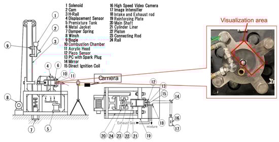
Figure 1.
Scheme of RCEM with details of “visualization area” from the imaging system.
- A tank used for the pre-mixing of the gaseous charge at controlled pressure.
- Intake/exhaust control rod for the filling/emptying phases of the charge.
- Cylinder with a PC module equipped with a spark plug.
- A flat head piston mounted by means of the connecting rod to the power actuation system.
- A flame imaging sub-system.
- Measurement equipment.
The main specifications of the RCEM are listed in Table 1, also including the baseline experimental conditions.

Table 1.
Main characteristics of RCEM and baseline experimental conditions.
The RCEM operates the compression stroke via an automatically controlled mechanical device, which is essentially composed of a cam whose movement determines the piston actuation through the free terminal of the control rod connected to the piston. In particular, the cam is moved by a hydraulic pump and performs two movements in a vertical direction; only the descent movement (drop phase) is useful for compression actuation. The RCEM control software (LabviewTM) allows for the measurement of the MC pressure trace collected via a piezo-electric pressure transducer (Kistler 6054BR-3-1, Kistlet group, Winterthur, Switzerland), installed at the cylinder head and located in a lateral position with respect to the centrally mounted small PC module. This pressure transducer shows a sensitivity of ±1.5% with a typical error range of 0.5 bar. The longitudinal axis of the PC is parallel and aligned with the main chamber one. PC volume includes the spark plug (NGK LFR7AIX-P 2900, Niterra Co. Ltd. sold under the NGK brand, Nagoya, Japan) with Hitachi 22448-4M50A direct ignition coil and is connected to the MC via six holes equally distributed on the circular section (60° hole-to-hole angle). The PC device was designed with two different internal shapes but with the same total volume: PC volume is approximately 0.6% of clearance volume of the RCEM cylinder. This percentage is slightly lower than the levels commonly adopted in the literature studies on pre-chamber systems (1–5%) [24,25]. However, this design parameter falls within the suggested range by the study of Li et al. [26]. They justified the use of a small PC volume in natural gas passive PC engines considering the trade-off between the ignition energy and the scavenging efficiency.
Inlet gases (air and fuel) are mixed in a dedicated tank and controlled by a separate mass flow controller. The chamber is heated to a desired temperature using a heater, controlled by an OMRON E5CS-RKJU-W electronic temperature controller (Omron Corporation, Kyoto, Japan). During RCEM experiments, piston position is measured with a high-speed sensor, composed by an encoder and scale (measuring band) models. This sensor is characterized by a low distance resolution suitable for the typical piston speeds of the considered tests. Concerning the imaging system, combustion visualization of the turbulent jets into the main chamber was performed with a high-speed color camera coupled to an objective lens. The resolution and frame rate of the adopted camera were 480 × 640 pixels and 10,000 frames per second, respectively. The camera lens aperture was properly set for all the experimental tests to adequately capture the initial illumination of turbulent jets in the MC. The acquired images were processed using dedicated software. More details on the RCEM experimental setup can be found in the previous authors’ work [27]. As mentioned above, different PC configurations were considered to study their effects on combustion evolution and the appropriate internal PC design aiming to avoid flame extinction. To this aim, Table 1 shows that the cylinder has been equipped with three different PC geometrical variants. In particular, the experiments were carried out using three types of PC distinguished into two different categories for the internal shape: short cylindrical shape (labeled as Short PC) and long funnel one (labeled as Long φ4/5). They present the same geometrical features, orientation and distribution of the holes, and they also practically have the same total volume. Figure 2 proposes the drawings of the individual PCs adopted in this study with the indication of the main geometrical dimensions. Furthermore, Table 2 illustrates a summary of the relevant PC geometrical data. Looking at both Figure 2 and Table 2, the unique difference between the three PC designs is the internal area and the length of the flow path.
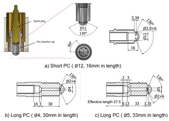
Figure 2.
Scheme of PC variants: (a) Short; (b) Long φ4; (c) Long φ5.
Table 2.
Comparison of geometrical characteristics of pre-chambers.
Referring to the experimental conditions, Table 1 shows the baseline ones for the combustion analyses. They present the same level of A/F ratio (stoichiometric mixture), equivalent engine speed and spark timing. The latter was selected in the examined cases to realize a combustion developing around the TDC. First, different PC geometries were investigated with the same initial thermodynamic conditions of premixed charge, highlighting possible flame extinctions. Starting from this last evidence, some solutions aiming to avoid extinction are explored as better detailed in the following section.
3. Simulation Models of RCEM
A hierarchical 0D/3D numerical procedure is employed to tune the turbulence in the RCEM [28]. A 3D CFD model of the RCEM is developed, and a single 3D analysis is carried out to derive turbulence intensity evolutions for a pre-defined PC geometry. These turbulence outcomes for both PC and MC are considered as reference data to be replicated with the 0D model of the RCEM. Apart from the turbulence simulation, no additional investigations are carried out using the 3D CFD model. Combustion development and quenching-induced flame extinction are then studied employing the 0D RCEM model (GT-PowerTM).
3.1. 3D Model
A cold flow simulation reproducing the compression and expansion phases of the machine is performed with the commercial 3D CFD CONVERGE code. The geometrical symmetry of the RCEM system was exploited, aiming to utilize only a 1/6 sector of the overall chamber geometry. An integrated domain for PC and MC was used, including a single orifice connecting PC and MC volumes and adopting as a reference the Short PC. Such simplification of system geometry has been chosen here to lower the computation effort in performing only the 3D turbulence analysis under cold flow. However, the use of a 1/6 sector of the overall geometry involves the effect to neglect the jet-to-jet interaction, which may induce a not negligible impact on turbulence enhancement in the MC [29], leading to a potential underestimation of turbulence in the MC [30]. As for 3D turbulence simulation, the k-ε RNG sub-model for compressible flows is used. A mesh for the considered domain has been defined using hexahedron cells with a base mesh size of 2.0 mm; proper local mesh refinements are applied, including the ignition source, the PC volume and the single hole connecting two chambers and the wall boundaries of domain. The adaptive mesh refinement (AMR) technique is also used to control the mesh width along the simulation according to the physical parameters. The smallest cell size achieved in locally refined areas via AMR technique is equal to 0.125 mm. Figure 3 reports a representation of the adopted 1/6 sector mesh. The following Table 3 includes a list of the main modeling setup and mesh characteristics.
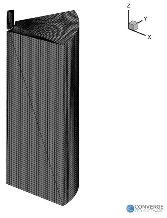
Figure 3.
Sketch of the employed 3D mesh model at the event of test start (−180 CAD ACTDC).
Table 3.
3D model setup and mesh characteristics.
This mesh setting was borrowed from a previous authors’ work [27], which was focused on studying the combustion of the same RCEM via 3D analyses, and it proved to be the most suitable choice for achieving a good compromise between accuracy and computational effort. 3D simulation is carried out assigning the initial pressure of 130 kPa, the initial gas temperature of 343 K and a stoichiometric air/methane mixture. The latter was assumed as a real gas described by Redlich-Kwong equation of state. Wall temperatures are fixed at constant levels, imposing a value of 373.15 K in the heated area (i.e., MC walls) and 293.15 K in the non-heated area (i.e., PC walls). Turbulent kinetic energy and dissipation are initially set to very low levels both in PC and MC volumes.
3.2. 0D Model Description and Setup
The RCEM geometry (left side of Figure 4) is schematized in the GT-Power code developing a 0D model that includes the volumes of the main chamber (MC) and the pre-chamber (PC). These volumes are connected with an orifice object, simulating the overall cross-sectional area of six PC holes. Geometrical characteristics of the RCEM system are specified in a dedicated block connected to the MC volume, which also includes as input the angular evolution of the piston position. A simple scheme of the RCEM model is proposed on the right side of Figure 4.
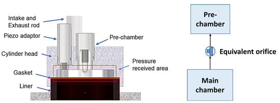
Figure 4.
Detail of RCEM equipped with pre-chamber and related 0D model.
In both chambers, mass and energy balance equations are solved, while the exchanged mass between PC and MC volumes is computed according to the filling and emptying technique. Phenomenological sub-models of turbulence, combustion and wall heat transfer are implemented into the code through user routines and then applied both to the PC and MC. A two-zone approach (burned and unburned gas regions) is employed after the spark event for the combustion modeling, while a single zone schematization is followed in both chambers before combustion. Additionally, a flame quenching sub-model has been specifically developed and integrated into the code to compute the quenching diameter at PC holes, aiming to evaluate the extinction tendency of flame jet. An in-depth discussion of the combustion and quenching sub-models is presented in the following sub-sections. As concerns the model setup, the single test is simulated, providing different experimental parameters as input data, including initial pressure, temperature and composition of the premixed air/fuel charge. Specific attention has also been given to the proper definition of the initial charge composition in the case of methane/hydrogen blends, taking into account the modification of the stoichiometric air/fuel (A/F) ratio by varying the hydrogen percentage [31]. Spark timing and PC/MC wall temperatures are imposed according to experimental tests and the 3D analysis. Also, the volume evolution into the main chamber (consequently, the piston position) is taken from the measurements and given as further model input. The simulation is performed covering the entire experiment (compression-expansion strokes) with a fixed time-step of 0.1 CAD to properly capture the flow dynamics in the system.
3.3. Combustion and Heat Transfer Models
The classical two-zone subdivision (i.e., burned and unburned regions) is considered to describe the combustion process both in PC and MC of the RCEM. The combustion in the MC volume is promoted during its early stage by turbulent jets ejected from the PC. This process leads to a re-arrangement of the classical fractal sub-model consisting of a modification of the burn rate term as a sum of two contributions in Equation (1): the first term related to the fractal burning rate of the flame propagation and the second one to the turbulent jets.
The fractal burning rate is classically determined by Equation (2):
where is the density of unburned gas, the laminar flame area, the laminar flame speed and Σ the flame wrinkling. This last parameter is defined as the ratio between the turbulent and the laminar flame areas. Following the fractal approach, the flame wrinkling is evaluated according to Equation (3):
where and are the length scales of maximum and minimum wrinkling, and is the fractal dimension. All the above variables are determined solving the user-defined turbulence model, deeply discussed in [32].
The burn rate enhancement by turbulent jets is computed similarly to the eddy burn-up formulation and is reported by Equation (4):
The fresh charge is entrained by jets and the entrainment rate, , is evaluated through a semi-empirical correlation included in [33]; subsequently, the entrained gases are burned in a characteristic time scale, τ, equal to the ratio between the Taylor length scale, , and the laminar flame speed, [34]. The fractal burning rate contribution, , is applied both to PC and MC volumes with a differentiated evaluation of local levels of flame wrinkling, laminar flame speed (LFS) and laminar flame area. The of pure methane and hydrogen/methane blends is determined by adopting a chemical-derived correlation originally proposed by Bougrine et al. [35], extending the validity domain of the experimental correlations to high pressure/temperature levels. This LFS correlation presents a power-law analytical formulation valid for any volumetric percentage of hydrogen in methane (from 0% to 100%), also including the residual dilution effects as illustrated in Equation (5).
is a reference laminar flame speed depending on hydrogen molar fraction, , and air/fuel ratio, ; p is the pressure, is the unburned temperature, is a term multiplying the function of residual gas f and including dependencies on hydrogen fraction, unburned temperature and air/fuel ratio. The exponents and include dependencies on all the variables p, , and . f is a cubic function of residual gases, , and and are reference pressure and temperature, respectively. As an example, Figure 5 proposes the LFS levels deriving from the adopted correlation for a stoichiometric mixture and null residual gas. A comparison between the LFS values of pure methane and a single methane/hydrogen mixture (30% vol. H2) has been proposed by varying the pressure and temperature of unburned gas. Interestingly, the LFS correlation returns results in good agreement with chemical 1D LFS data (overall dataset containing more than 62,244 points) using premix code from Sandia and Gri-Mech 3.0 mechanism [36], and it well captures the flame speed increase induced by the hydrogen addition. At moderate/high hydrogen contents in the mixture (over 80% H2 by volume), the LFS correlation exhibits greater prediction errors reaching an average error of ~6%, which can be considered acceptable [35]. Finally, a user-developed procedure has been employed to compute the laminar flame area of MC and of three analyzed PC configurations, similarly to a previous authors’ article [34]. In this way, the MC and PC laminar flame areas are tabulated and properly inquired during the simulation. As for the PC, this procedure requires as input data the dimensional features of the internal geometry and the definition of the spark plug location inside the PC. As for the MC, the input data are represented by main geometrical characteristics (bore/stroke, compression ratio, flat piston shape) and the definition of multiple flame kernel positions along the oriented direction of turbulent jets. These last locations are fixed and assigned based on previous studies of the authors on similar pre-chamber systems [34]. From each ignition site, the flames propagate spherically until they intersect with each other and with the combustion chamber walls. Finally, they collapse and fill the entire chamber. Figure 6 shows a simple representation of the adopted flame front developments in both the PC and MC. The ignition points in the MC are uniformly distributed and equal to the number of PC holes.
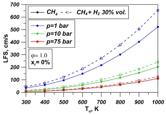
Figure 5.
Laminar flame speed variation as a function of hydrogen content in methane/hydrogen blend and of pressure/temperature of unburned gas (stoichiometric condition and null residual content).
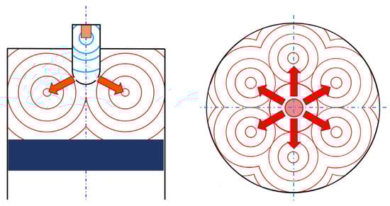
Figure 6.
Frontal and upper view of a simple schematization of flame developments in PC and MC volumes.
Figure 7 illustrates the evolution of the laminar flame area of MC as a function of flame radius for a fixed piston position. The MC flame area evaluation is repeated for several piston positions to cover the entire piston stroke. Consequently, a look-up table is generated collecting different flame areas in the MC at varying flame radius and the piston position. A similar estimation is performed for the pre-chambers, obtaining the PC flame area, which is exemplary represented in Figure 7 for the Short PC. In the PC volume, the flame front very soon interacts with the walls, leading to a lower flame area with respect to the one in the MC. For the PC, a fixed flame center corresponding to the spark-plug position has been assumed, allowing for the creation of a compact look-up table of flame areas that only depend on the flame radius. Ultimately, the overall procedure favors a decreased computation effort if compared to an online flame area calculation but requires a preliminary computation of flame area tables for both MC and PCs.
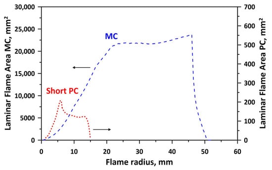
Figure 7.
Laminar flame area of MC and Short PC against the flame radius.
Concerning the heat transfer process between the solid walls and the working fluid, it is modeled using the Woschni correlation [37], which governs the convective heat exchange during compression and combustion/expansion phases of the RCEM. The boundary wall temperatures required by Woschni correlation are assigned as input data in 0D model and they are set uniformly to the experiments. Despite not being included here for brevity, the heat transfer multiplier was calibrated using non-reactive pressure trace via a trial and error procedure.
3.4. Flame Quenching Model
The flame quenching sub-model is developed to specifically compute the quenching at the pre-chamber (PC) holes, which is the PC section mostly affecting the quenching behavior. This sub-model assesses a possible flame extinction through comparison of computed quenching diameter, , with a critical diameter, , defined in the following. Quenching diameter at PC holes, , is derived from the calculation of single plate quenching distance, . The latter is obtained starting from the definitions of the Peclet number, , and the flame thickness, , as illustrated by Equation (6):
Boust et al. [38,39,40] proposed a reliable correlation for the Peclet number, essentially based on boundary and thermodynamic conditions and on the normalized wall heat flux, . This correlation presents an inverse dependence on the as reported by Equation (7):
where is the unburned gas temperature, is the burned gas temperature and is the wall temperature. The latter controls the wall heat flux and a higher wall temperature induces a decrease in the quenching distance, thus reducing the risk of flame quenching.
The wall quenching at PC holes more closely resembles the case of side wall quenching (SWQ). As highlighted by the analyses of Boust [38] and further confirmed by the numerical study of Poinsot [41], the Peclet number during the SWQ falls within the range . Consequently, the normalized wall heat flux varies between . According to the above considerations, in the present study in Equation (7) is assumed equal to 0.08 as the average level of the suggested range and this variable represents the unique tuning parameter in Equation (7). The latter exerts a certain sensitivity on quenching prediction. Indeed, compared to the obtained value of quenching distance (i.e., with reference ), by setting the lower limit of the quenching distance increases by ~30% while by assuming the upper limit of the quenching distance is reduced by 20%. As better clarified in the following, this assumption does not alter the predicted trends of quenching diameter at varying the operating condition. As concern the flame thickness in Equation (6), it is calculated according to Equation (8):
where is the thermal conductivity; is the specific heat at constant pressure. As suggested by the work in [42], the thermal conductivity is here computed according to Equation (9):
with and two model constants equal to 2.68 × 10⁻² and 0.9, respectively. The mean gas temperature, , is indeed evaluated with Equation (10):
In the above relation, the wall temperature, , is provided as an input parameter, deriving from the experimental tests, and it was assumed to be constant throughout the entire test period. In Equation (8), the thermodynamic properties of unburned gas, including the density and specific heat at constant pressure, are determined assuming the mean temperature, . Once the single plate quenching distance is computed referring to the combination of the previous presented Equations (6)–(10), the quenching diameter is obtained from the single plate quenching distance, adopting the scaling law proposed by Lavoie in [43]:
Some experimental activity conducted by researchers in the past years [44,45] confirmed the scaling law expressed by Equation (11). However, this equation does not assume a general validity from the more recent numerical/experimental studies [46,47,48], taking into account a broad range of pressures, temperatures, equivalence ratios and hydrocarbon fuels. Recently, Zirwes et al. [49] provide data of the ratio in the range of 0.15–0.25 for stoichiometric air/methane mixtures, SWQ configuration and ambient to moderately elevated pressure. The latter study is consistent with the Lavoie assumption and, ultimately, the adopted scaling law in Equation (11) can be assumed as a reasonable engineering-level approximation well suited to the test conditions discussed in the present work.
Finally, to evaluate a possible flame extinction at the PC holes, the above calculated quenching diameter, , is compared with a “critical” diameter of PC holes, . From a theoretical point of view, this assessment leads to two conditions:
- 1.
- For , the flame passes the PC holes and therefore no extinction phenomenon verifies.
- 2.
- As soon as the quenching diameter approaches or even overcomes the critical level, that means for , the quenching phenomenon appears.
Considering that the RCEM model simulates a single test reproducing the average combustion conditions in the PC and MC volumes, the resulting quenching diameter is interpreted as an indicator of extinction tendency of PC flame jets when compared to the critical threshold. Therefore, for an assigned PC geometry, the higher the experimental probability of flame extinction over repeated tests, and the closer is the computed quenching diameter to the critical one of PC holes. This last represents the effective diameter of the holes, which is obtained based on the discharge coefficient, and on the geometrical diameter, . This leads to the following Equation (12):
Generally, the discharge coefficient in Equation (12) effectively depends on the Reynolds (Re) number, especially at low Re levels where the viscous effects are dominant; in the specific case of PC holes, they experience very high gas velocity leading to a sufficiently high Re regime (fully turbulent flow); in this condition, the flow is dominated by inertial losses and the discharge coefficient is weakly dependent on Re number, which varies within a plateau region, allowing for quasi-steady treatment. Therefore, as reported by different literature works [50,51,52], for circular orifices can be assumed almost constant in the considered application with an average value of 0.6. Ultimately, the critical diameter value for the quenching of flame jet is ~1.5 mm.
As a final remark, it is the case to point out that the proposed 0D quenching sub-model is not able to capture the 3D local effects of flow/turbulence fields, or the ones induced by 3D geometry or by spatial gradients of fluid properties. For these intrinsic limitations, the quenching sub-model cannot replicate the experimentally observed asymmetric extinction of flame jets at PC holes shown in the following Figure 8.
4. Results and Discussion
This section reports both experimental and numerical outcomes. In the first stage the experimental outcomes are presented, mainly highlighting the effects of PC geometry and hydrogen content in methane on the flame extinction through flame images. In a second phase, the numerical activity is carried out to reproduce the flame extinction tendency with validated 0D model.
4.1. Experimental Outcomes
The experimental tests on the RCEM have been realized by exploring different PC geometries and fuel types, employing fixed spark timing (ST = −16 CAD AFTDC) and stoichiometric air/fuel ratio (λ = 1). Some details on the experiments have been included in Table 4. This last shows that the initial test conditions are substantially the same for all cases, except for the Long φ4 PC configuration for which the initial pressure has also been increased (passing from 130 kPa to 150 kPa) to facilitate the transition from an unstable combustion (with extinction of jets) to a stable combustion (labeled as normal combustion).
Table 4.
Experimental tests with RCEM under normal combustion and stoichiometric conditions; case #2(*) represents the critical PC shape with extinction of flame jets and unstable combustion.
The extinction condition of the flame jet is determined through the combustion images when one or more jets emerging from the PC hole are not visible in the main chamber. In particular, the jet extinction criterion is based on the non-burnt mixture exiting the MC and on the measured OH luminosity. These experimental details have been better specified in already published works [23,27]. The investigated PC geometries present six holes uniformly distributed, resulting in six jet directions with a jet-to-jet angle of 60 degrees. If the flame jet does not appear along a single direction, then it is assumed that an extinction phenomenon is occurring. As an example, Figure 8 shows at a fixed angular position (3 CAD after TDC) the acquired combustion images for the case of normal combustion with all visible flame jets (left side) and the case characterized by two extinct jets (right side) along the directions located in the bottom-right corner of the visualization area. Experiments related to the effects of PC geometry are carried out using all PC variants (Short and Long types) included in Figure 2 and referring to the pure methane fuel at stoichiometric conditions (cases #1, #2(*) and #3 in Table 4). For each case, repeated experimental tests are conducted, revealing a non-zero probability of flame jet extinction exclusively for the Long φ4 PC configuration. Under this PC design, a limited number of repeated tests has been realized, which ranges from the minimum of 8 to the maximum of 13. These tests are considered sufficient to evaluate the flame extinction phenomenon, reaching a pressure dispersion in the MC of ~2.5 MPa over 13 repetitions. Despite the small number of tests, it is important to underline that a secondary goal of the experiments is the identification of the pressure traces associated with stable combustion for the subsequent model validation. The outcomes in terms of combustion images for three different PC geometries are plotted in Figure 9 as a crank angle-based sequence, illustrating the evolution of flame jets into the MC volume. Figure 9 shows that six flame jets are visible both for Short and Long φ5 PC types. A different behavior occurs for the Long φ4 PC (middle image sequence in Figure 9), where two flame jets are not visibly captured in the bottom-right side of images, even under a well-developed combustion phase (i.e., angular position of 3.2 CAD AFTDC). The experimental outcomes in Figure 9 indicate that the extinction phenomenon highly depends on the PC internal shape, with the Long PC type being more prone to cause flame extinctions and unstable combustions.

Figure 8.
Overview of visible (normal combustion on the left); invisible flame jet (jet extinction on the right side) related to Long φ4 PC, methane with an initial pressure of 130 kPa; the arrows reported in figure indicate the directions of the jets.
Figure 8.
Overview of visible (normal combustion on the left); invisible flame jet (jet extinction on the right side) related to Long φ4 PC, methane with an initial pressure of 130 kPa; the arrows reported in figure indicate the directions of the jets.


Figure 9.
Combustion images for cases #1, #2(*) and #3 (methane fuel).
Figure 9.
Combustion images for cases #1, #2(*) and #3 (methane fuel).

Experiments are also conducted to investigate the effects of hydrogen addition, aiming to improve the flame extinction for the critical pre-chamber configuration, namely Long φ4 PC. RCEM tests are carried out by recording the combustion images for the main chamber, mounting a Long φ4 PC, and with the initial pressure of 130 kPa. Combustion images are acquired for three different methane/hydrogen blends: cases #4, #5 and #6 in Table 4. Recorded combustion images in Figure 10 underline that flame jets appear earlier in the visualization area of MC when the hydrogen is added to the methane. Since all the tests are carried out with the same ignition system and spark timing, the advanced jet ejection angle in the case of H2 blending is a result of an increased flame speed in the PC due to the fast laminar flame velocity of H2. The most relevant outcome emerging from the comparisons of flame jets in Figure 10 is represented by the absence of jets extinction passing from the test with pure methane (H2 = 0%—top images sequence) to all the other cases with methane/hydrogen mixtures. Interestingly, experiments confirm that even small quantities of hydrogen (i.e., 10% by vol.) help to improve the ignition property of air/fuel mixture, lowering the quenching tendency of flame jets thus reducing the extinction probability of flame on repeated RCEM tests. More in-depth experimental studies on the RCEM were conducted in a previous paper [27], which can be analyzed for further details on the RCEM experimental results.
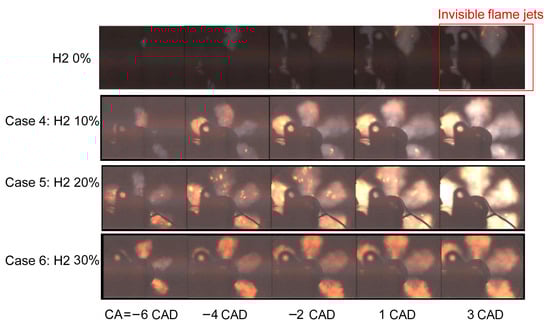
Figure 10.
Comparisons of flame jets images for methane/hydrogen blends (cases #4–6, H2 = 10–30% vol.) vs. pure methane fuel (H2 = 0%).
4.2. Numerical Outcomes
Two main groups of validation calculations have been performed. First, 3D turbulence analysis is realized considering the cold flow operation with initial pressure of 130 kPa and initial gas temperature of 343 K. Then, combustion simulations are carried out referring to the experimental cases listed in the above Table 4. Since the experimental outcomes demonstrated the extinction of flame jets and the unstable combustion for the Long φ4 PC with an initial pressure of 130 kPa and methane fuel, the combustion validation for this case has been carried out referring to a normal combustion condition, which is reached with a higher initial pressure equal to 150 kPa.
4.2.1. Turbulence Validation with 3D Outcomes
The reliability of the developed 0D model of the RCEM is evaluated against the outcomes of the 3D model, in terms of turbulence evolutions in both chambers, assuming as the reference PC geometry the one corresponding to “Short PC”. A virtual test without combustion (cold flow) is carried out on an RCEM to compare the turbulence results of 0D and 3D models. Under the latter condition, the 0D turbulence sub-model is properly tuned to align the turbulence results to the ones extracted from the 3D simulation, following the same procedure reported in a previous authors’ activity [28]. In this perspective, the 3D-related profile of the integral length scale, both for PC and MC volumes, is adequately reproduced through a sequence of mathematical functions (Figure 11a,b) and then given as input data for the 0D model. A trial-and-error procedure was followed to identify the tuning constants of the turbulence sub-model; once tuned, the model demonstrates to correctly reproduce the turbulence intensity level and trend both in MC and PC as depicted by Figure 11c and Figure 11d, respectively.
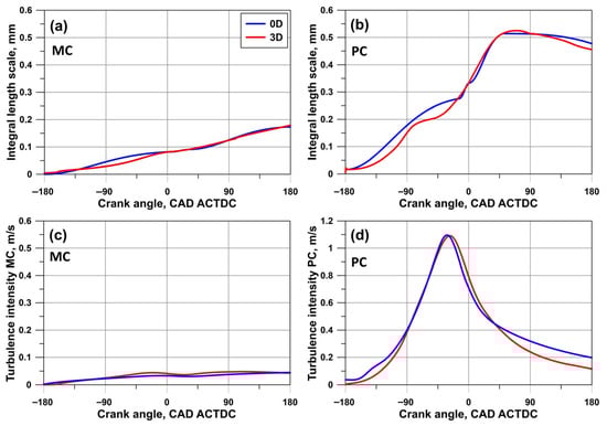
Figure 11.
Comparison between 0D and 3D outcomes: (a) integral length scale in MC; (b) integral length scale in PC; (c) turbulence intensity in MC; (d) turbulence intensity in PC.
Interestingly, Figure 11c highlights that the turbulence level in the MC exhibits a weakly increasing trend during the test, even if a very low overall level is attained. Greater values can be found in PC, where a turbulence peak is realized just before the end of the compression phase (Figure 11d). Indeed, a turbulence increase during compression is related to the PC charge filling, followed by a turbulence decrease along the expansion due to the charge exiting the PC. Once correctly tuned, the identified turbulence model constants are kept unchanged at varying the PC configuration and for the subsequent combustion simulations in the RCEM device. For the sake of completeness, a further verification of the 0D turbulence model has been realized under combustion conditions through assessments with 3D CFD outcomes.
4.2.2. Combustion Validation
The 0D model of the RCEM has been validated to replicate the combustion process under different operating conditions and various PC geometries (Table 4). In a preliminary phase, combustion validation is carried out considering the stoichiometric air/methane mixture for all the investigated PC variants (i.e., cases #1, #2 and #3). These validation cases refer to normal combustion conditions in the RCEM experiments, avoiding the occurrence of very delayed combustion or even complete failure in combustion process for the MC due to severe flame extinction. For this reason, case # 2* is not taken into account for combustion model validation.
The outcomes included in Figure 12a–c depict the numerical/experimental comparison of the instantaneous pressure profiles in the MC for these three cases. In the figures, the zero angle corresponds to the phase when the piston reaches the TDC, while −180 CAD AFTDC refers to the initial condition of the experiment. Observing Figure 12, during the compression phase, the numerical pressure trace (blue line) is almost superimposed to the average measured pressure one (black line), indicating the model ability in capturing the pressure modification arising from the volume variations. The figure also shows that the combustion start in the MC is well predicted in all cases; also, the computed pressure evolution during combustion (i.e., overall shape, peak level and angular phasing) is correctly aligned with the experimental counterpart. On the other hand, major prediction errors emerge along the expansion phase for the Long φ4 PC, which can probably be ascribed to a not refined simulation of the expansion-related piston position.
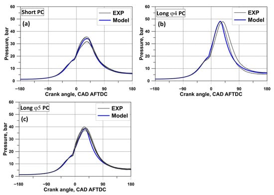
Figure 12.
Comparison between experimental and model pressure traces in the MC for the stoichiometric air/methane mixture: (a) Short PC; (b) Long φ4 PC; (c) Long φ5 PC.
Once the combustion model is tuned under the conditions included in Figure 12, the identified model tuning constants are kept unchanged for the subsequent combustion analyses of the RCEM by employing various methane/hydrogen blends and the PC configuration exhibiting the highest experimental flame extinction probability (i.e., Long φ4 PC). Indeed, Figure 13 shows the numerical/experimental comparisons of pressure evolution in the MC for three cases labeled as #4, #5 and #6 in Table 4. Despite some model inaccuracies (mostly visible for the case with 30% H2 vol.), the computed pressure evolution during the combustion substantially follows the trend of the average experimental data; Figure 13 confirms that the increasing pressure peak levels at rising the H2 percentage are adequately replicated by the model. These outcomes underline the model ability to handle combustion velocities related to various methane/hydrogen blends, mainly thanks to the appropriate definition of laminar flame speed correlation.
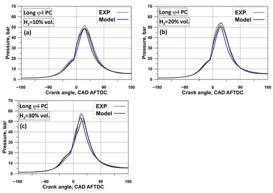
Figure 13.
Comparison between experimental and model pressure traces in the MC for different methane/hydrogen blends and Long φ4 PC: (a) 10% vol. H2; (b) 20% vol. H2; (c) 30% vol. H2.
Figure 14 reports the spark timing in the PC, the numerical/experimental assessments of MFB2% and MFB50% angles in the MC with the related average absolute errors. The figure demonstrates that the model accurately reproduces the angle of MFB2% in the MC, reaching an average absolute error between experiments and numerical outcomes equal to 0.5 CAD. This result indicates an appropriate simulation of PC combustion evolution for all the examined cases. Once again referring to Figure 14, the model captures the experimental trend of MFB50% angle in the MC, highlighting that Long φ4 PC exhibits the fastest combustion process with respect to the other PC shapes. In addition, for the Long φ4 the MFB50% angle is further advanced if the H2 percentage mixed with methane is increased. Small H2 amounts are capable to realize a more optimized combustion, moving the MFB50% angle in the MC towards the MBT condition (i.e., 8−10 CAD AFTDC). Overall, an acceptable prediction of the MFB50% angle in the MC is achieved (average absolute error of 2.3 CAD). Summarizing, the discussed outcomes highlight a good capability of the combustion model to simulate the average thermodynamic histories occurring in the MC of the RCEM by varying the experimental tests, without the need for a re-tuning of the model. This aspect confirms the reliability of the developed RCEM model, allowing for its application to the numerical study of flame extinction conditions.
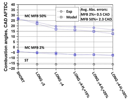
Figure 14.
Experimental/numerical comparison of MFB2% and MFB50% in the MC for various cases.
4.2.3. Flame Extinction
This section reports the numerical outcomes arising from the application of the quenching sub-model to the tested cases with the aim of replicating the experimental conditions of the flame extinction. A first assessment has been carried out between the Short and Long PC shapes, assuming the same initial conditions of pressure and temperature (i.e., p = 130 kPa and T = 343 K) for the intake charge and adopting a stoichiometric air/methane mixture. Looking to the comparison of computed quenching diameters for the examined cases, Figure 15a highlights that Long φ4 PC presents the highest quenching diameter at the event of combustion start in the MC with respect to the ones related to Short PC and Long φ5 PC; these quenching diameters are marked with a star in the below figure. Therefore, Long φ4 PC represents the most critical PC geometry for its internal shape, showing the quenching diameter closer to the critical one of PC holes. The simulation outcomes put into evidence that the PC internal geometry influences the evolution of thermodynamic conditions (i.e., unburned temperature and pressure) into the PC volume as a consequence of a different combustion development; for the considered PC shapes, the computed average pressure/temperature levels in the PC induce a higher laminar flame thickness for the Long φ4, mainly deriving from a more penalized LFS at the angular event of jet ejection. In other words, the model predicts the greatest tendency to the extinction of flame jet for Long φ4 PC basing on the average cylinder trace; although the 0D model is limited in forecasting only the extinction trend of the flame jet at varying the internal PC geometry, it returns an outcome aligned with the experiments, highlighting the existence of an extinction probability only for this PC type (~54% over 13 tests). Additionally, Figure 15a underlines the model ability in correctly reproducing an advanced combustion onset in the MC (due to earlier jet ejection from PC) for both the Long PC shapes compared to the Short one. Still referring to Figure 15a, it is apparent that the model confirms a faster combustion process in the PC and therefore an earlier MC combustion initiation for the case of Long φ4 with respect to Long φ5. The fastest combustion process occurring in the Long φ4 PC compared to the Long φ5 PC is dictated by a greater flame wrinkling, as highlighted by Figure 15b. The identified most critical PC configuration for the extinction issue (Long φ4 PC) has been selected to continue with the simulations, considering the effects of modified initial conditions and fuel composition similarly to the measurements. These effects are numerically studied here to capture the experimental mitigation of the extinction phenomenon.
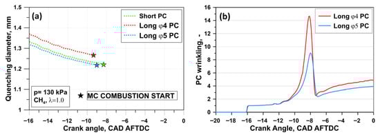
Figure 15.
Evolution of quenching diameter at varying the PC geometry (a); Flame wrinkling in the PC device (b).
Figure 16a depicts a comparison of quenching diameters for Long φ4 PC at two different levels of initial gas pressure. The model returns a reduced quenching diameter at the combustion start in the MC by increasing the initial pressure (from 130 kPa to 150 kPa) of the inducted air/fuel charge. This numerical outcome suggests an improvement in the flame extinction issue, and it is consistent with the experimental trend and literature data [53,54]. Here, the model forecasts the reduction in laminar flame thickness, which involves a lowering in the quenching diameter with a substantially unchanged Peclet number. The lowering of the laminar flame thickness can be ascribed to the prevailing effect of the increased unburned gas density. The effect of the modified fuel composition, through the hydrogen addition to methane, has also been simulated as an alternative technique capable of lowering the extinction tendency of the critical Long φ4 PC. In this case, the fast LFS of H2 represents the main driver for the flame extinction mitigation. In this perspective, the model correctly recognizes a higher LFS with increasing hydrogen content in the hydrogen/methane mixture, as clearly underlined by Figure 5. This behavior involves the lowering of flame thickness and, in a proportional way, the reduction in the quenching diameter [54], as visible in Figure 16b. The latter confirms that the model also captures the H2 impact on combustion evolution, forecasting an earlier jet ejection event from PC to MC as the H2 content increases, thus promoting an earlier burning process in the MC. The star symbols in Figure 16b indicate the slight advance of the MC combustion start and a more favorable quenching diameter to avoid extinction at increasing the H2 percentage. It is worth specifying that the quenching sub-model validity has been evaluated in all the experimental conditions by verifying that the Peclet number, PeQ, falls within the typical range of SWQ for the extinction of flame jet. Even if details are not provided here for brevity, all analyzed cases showed an instantaneous PeQ level at the combustion onset in the MC equal to ~13.6, confirming the assumption made for the tuning constant in Equation (7). Figure 17 shows a reduction trend in the experimental probability of flame extinction at decreasing the quenching diameter, when considering all the tests performed for the Long φ4 PC. In this figure, the test is plotted with an empty bubble symbol if the initial gas pressure is 130 kPa; the filled bubble indicates an increased pressure level equal to 150 kPa. The diameter of the bubble is directly proportional to the hydrogen content in the methane/hydrogen mixture. The number of experimental repeated tests is specified in the top-left corner of each bubble. Starting from the most critical case characterized by an extinction probability of 54%, Figure 17 reveals that the adoption of 10% H2 by volume or a pressure increase equal to 20 kPa are enough to reduce the extinction probability by about 6 times. However, both conditions involve a much lower decrease in the quenching diameter, slightly less than 10%. It is worth highlighting that a certain experimental dispersion for the pressure profiles both in PC and MC occurs over repeated RCEM tests; the present model version does not consider this aspect in predicting the quenching diameter but only an average pressure profile. Beyond this consideration, it is the case to remark that an RCEM operating as a single-shot experimental facility does not capture the cycle-to-cycle variability (CCV) inherent of ICEs. Indeed, the RCEM does not work continuously according to a thermodynamic cycle but the single experiment is independent and starts from well-controlled initial conditions. Therefore, the outcomes deriving from the PC RCEM model cannot be directly extended to PC SI engines regarding the combustion variability. Anyway, the RCEM model and experiments provide valuable information to understand the fundamental mechanisms of pre-chamber ignition complementing the engine analyses.
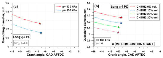
Figure 16.
Effect of initial pressure on quenching diameter for the Long φ4 PC (a); evolution of quenching diameter at varying the hydrogen percentage for the Long φ4 PC (b).
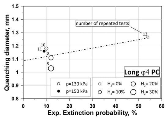
Figure 17.
Correlation between computed quenching diameter and experimental extinction probability for tests on Long φ4 PC.
5. Conclusions
In this work, numerical and experimental investigations have been conducted to study the effects of pre-chamber design, initial charge conditions and fuel type on combustion development and flame extinction tendency in an RCEM equipped with a passive PC device. Experiments realized with an air/methane mixture using an initial pressure of 130 kPa identified the critical PC design (Long φ4) presenting the highest flame extinction probability. Further RCEM tests with this critical PC configuration have shown that the flame extinction probability decreased from 54% to about 10% with an increase in the initial pressure of the air/methane charge (raising of 20 kPa) or with the addition of 10% H2 by volume in the methane. Subsequently, numerical analyses of the RCEM have been performed to reproduce the experimental combustion evolution and the related extinction tendency of flame jets. A 0D model of the RCEM has been developed in GT-PowerTM and integrated with advanced sub-models of turbulence, combustion and flame quenching. After a preliminary turbulence tuning with 3D results, the RCEM 0D model is validated for combustion evolution considering MC pressure traces of tests without flame extinctions and taking into account different PC variants, increased initial pressure and various hydrogen/methane blends. The extinction of the flame jet has been replicated through the quenching phenomenon at PC holes. The developed flame quenching sub-model has been tuned adopting a typical value of the Peclet number suggested for the SWQ, which mostly resembles the flame quenching at the wall of PC holes.
Then, the model has been applied to simulate the extinction tendency of the flame jet by comparing the computed quenching diameter with the effective diameter related to PC hole. The main numerical outcomes are summarized below:
- Consistently with the experiments, the model predicts the Long φ4 as the most critical PC design for flame extinction: in this PC design, the computed quenching diameter (~1.27 mm) is closest to the critical level (1.5 mm).
- RCEM simulations with the Long φ4 PC, realized by increasing the initial gas pressure (from 130 kPa to 150 kPa), lower the quenching diameter at PC holes (from ~1.27 mm to 1.16 mm), thus replicating the experimental trend of reduced flame extinction.
- The model successfully reproduces the measured effect of hydrogen addition to methane on the combustion process, forecasting advanced combustion phasing in the MC with hydrogen doping.
- The employment of small H2 percentages by volume in the methane/hydrogen mixture is sufficient to reduce the risk of flame extinction due to the decreased quenching diameter (from ~1.27 mm for the test without H2 to 1.18 mm for the one with 10% vol. H2).
The future development of this research activity will include the detailed analysis of the effects of PC configuration and hydrogen enrichment on the main gaseous pollutant emissions, including nitrogen oxides (NOx), unburned hydrocarbons (uHCs) and carbon monoxide (CO).
Author Contributions
Conceptualization, F.B. and L.T.; methodology, F.B., L.T. and E.U.; software, F.B., L.T. and E.U.; validation, E.U. and L.T.; formal analysis, L.T. and E.U.; investigation, R.S. and J.K.; resources, R.S. and J.K.; data curation, R.S.; writing—original draft preparation, L.T.; writing—review and editing, F.B., L.T., E.U., R.S., J.K. and E.M.; visualization, L.T.; supervision, F.B. and L.T.; project administration, F.B., R.S. and J.K.; funding acquisition, R.S. and J.K. All authors have read and agreed to the published version of the manuscript.
Funding
This research received no external funding.
Data Availability Statement
The original contributions presented in this study are included in the article. Further inquiries can be directed to the corresponding author.
Acknowledgments
The authors would thank Tokyo Gas Co Ltd. and HKS Co Ltd. for the pre-chamber design input and the technical collaboration.
Conflicts of Interest
The authors declare no conflicts of interest.
Abbreviations
The following abbreviations, symbols and greeks are used in this manuscript:
| 0D/1D/3D | Zero/One/Three-dimensional |
| A/F | Air/fuel ratio |
| ACTDC | After compression top dead center |
| AFTDC | After firing top dead center |
| AMR | Adaptive mesh refinement |
| CAD | Crank angle degree |
| CCV | Cycle-to-cycle variability |
| CFD | Computational fluid-dynamics |
| GHG | Greenhouse gas emissions |
| ICEs | Internal combustion engines |
| LES | Large eddy simulations |
| LFS | Laminar flame speed |
| MC | Main chamber |
| PC | Pre-chamber |
| RANS | Reynolds averaged Navier–Stokes |
| RCEM | Rapid compression and expansion machine |
| RCM | Rapid compression machine |
| RNG | Re-normalization group method |
| SI | Spark Ignition |
| ST | Spark timing |
| SWQ | Side wall quenching |
| TDC | Top dead center |
| TJI | Turbulent jet ignition |
| Symbols | |
| AL | Laminar flame area |
| Cd | Discharge coefficient of PC holes |
| cp | Specific heat at constant pressure |
| Fractal dimension | |
| dcrit | Critical diameter |
| dgeo | Geometrical diameter |
| dq | Quenching diameter |
| dq-sp | Single-plate quenching distance |
| f | Function of residual gases |
| Kλ | Tuning constant for thermal conductivity |
| Le | Lewis number |
| Length scale of maximum wrinkling | |
| Length scale of minimum wrinkling | |
| mb | Burned mass |
| mb,entr | Burned entrained mass |
| mentr | Entrained mass |
| p | Pressure |
| Reference pressure | |
| PeQ | Number of Peclet for quenching |
| Re | Reynolds number |
| SL | Laminar flame speed |
| SL0 | Reference laminar flame speed |
| t | Time |
| Tb | Burned gas temperature |
| Tmean | Average gas temperature |
| Tu | Unburned gas temperature |
| Tw | Wall temperature |
| Reference temperature | |
| Molar fraction of hydrogen | |
| Residual gas fraction | |
| Greeks | |
| Air/fuel ratio | |
| Tuning constant of thermal conductivity | |
| Exponent of pressure ratio in laminar flame speed | |
| Multiplier of residual gas function in laminar flame speed | |
| Exponent of temperature ratio in laminar flame speed | |
| δflame | Flame thickness |
| ε | Turbulent dissipation rate |
| λ | Relative air/fuel ratio |
| λt | Thermal conductivity |
| ΛT | Taylor length scale |
| ρu | Unburned gas density |
| Σ | Flame wrinkling |
| τ | Characteristic length scale |
| φQ | Tuning constant of quenching sub-model |
References
- European Technical Report. Available online: https://www.europarl.europa.eu/news/en/headlines/society/20190313STO31218/co2-emissions-from-cars-facts-and-figures-infographics (accessed on 6 December 2024).
- Thomas, M.; DeCillia, B.; Santos, J.B.; Thorlakson, L. Great expectations: Public opinion about energy transition. Energy Policy 2022, 162, 112777. [Google Scholar] [CrossRef]
- Ababneh, H.; Hameed, B.H. Electrofuels as emerging new green alternative fuel: A review of recent literature. Energy Convers. Manag. 2022, 254, 115213. [Google Scholar] [CrossRef]
- Berni, F.; Pessina, V.; Teodosio, L.; d’Adamo, A.; Borghi, M.; Fontanesi, S. An integrated 0D/1D/3D numerical framework to predict performance, emissions, knock and heat transfer in ICEs fueled with NH3–H2 mixtures: The conversion of a marine Diesel engine as case study. Int. J. Hydrogen Energy 2024, 50, 908–938. [Google Scholar] [CrossRef]
- Scalambro, A.; Piano, A.; Millo, F. Modelling thermodiffusive instabilities in hydrogen flames and their impact on the combustion process in a direct-injection hydrogen engine. Combust. Flame 2025, 282, 114457. [Google Scholar] [CrossRef]
- Li, L.; Wei, J.; Liu, H.; Wang, H.; Yao, M. The exergy analysis of low carbon or carbon free fuels: Methane, methanol, and hydrogen under engine like conditions. Fuel Process. Technol. 2023, 252, 107975. [Google Scholar] [CrossRef]
- Di Iorio, S.; Magno, A.; Mancaruso, E.; Vaglieco, B.M. Analysis of the effects of diesel/methane dual fuel combustion on nitrogen oxides and particle formation through optical investigation in a real engine. Fuel Process. Technol. 2017, 159, 200–210. [Google Scholar] [CrossRef]
- Sandhu, S.S.; Babu, M.K.G.; Das, L.M. Investigations of emission characteristics and thermal efficiency in a spark-ignition engine fuelled with natural gas–hydrogen blends. Int. J. Low-Carbon Technol. 2013, 8, 7–13. [Google Scholar] [CrossRef]
- Fru, G.; Thévenin, D.; Janiga, G. Impact of Turbulence Intensity and Equivalence Ratio on the Burning Rate of Premixed Methane–Air Flames. Energies 2011, 4, 878–893. [Google Scholar] [CrossRef]
- Wang, Y.; Su, Y.; Li, X.; Xie, F.; Yang, T.; Wang, B.; Shen, B. A new criterion and method for classifying combustion modes in a high compression ratio spark ignition engine. Energy Convers. Manag. 2024, 325, 119395. [Google Scholar] [CrossRef]
- Lanni, D.; Galloni, E. New Fuels and Advanced Combustion Modes for Innovative Internal Combustion Engines: An Overview. Energies 2024, 17, 6228. [Google Scholar] [CrossRef]
- Attard, W.P.; Fraser, N.; Parsons, P.; Toulson, E. A Turbulent Jet Ignition Pre-Chamber Combustion System for Large Fuel Economy Improvements in a Modern Vehicle Powertrain. SAE Int. J. Engines 2010, 3, 20–37. [Google Scholar] [CrossRef]
- Yu, D.; Chen, Z. Premixed flame ignition: Theoretical development. Prog. Energy Combust. Sci. 2024, 104, 101174. [Google Scholar] [CrossRef]
- Sementa, P.; Tornatore, C.; Catapano, F.; Di Iorio, S.; Vaglieco, B.M. Custom-Designed Pre-Chamber: Investigating the Effects on Small SI Engine in Active and Passive Modes. Energies 2023, 16, 5097. [Google Scholar] [CrossRef]
- Xu, G.; Kotzagianni, M.; Kyrtatos, P.; Wright, Y.M.; Boulouchos, K. Experimental and numerical investigations of the unscavenged prechamber combustion in a rapid compression and expansion machine under engine-like conditions. Combust. Flame 2019, 204, 68–84. [Google Scholar] [CrossRef]
- Allison, P.M.; de Oliveira, M.; Giusti, A.; Mastorakos, E. Pre-chamber ignition mechanism: Experiments and simulations on turbulent jet flame structure. Fuel 2018, 230, 274–281. [Google Scholar] [CrossRef]
- Mastorakos, E.; Allison, P.; Giusti, A.; De Oliveira, P.; Benekos, S.; Wright, Y.; Frouzakis, C.; Boulouchos, K. Fundamental Aspects of Jet Ignition for Natural Gas Engines. SAE Int. J. Engines 2017, 10, 2429–2438. [Google Scholar] [CrossRef]
- Wang, B.; Wang, Z. Experimental research on Pre-Chamber Jet ignition in Rapid Compression Machine and Natural Gas Engine. In Proceedings of the Ignition Systems for Gasoline Engines: 4th International Conference, Berlin, Germany, 6–7 December 2018. [Google Scholar]
- Hernández, I.; Shapiro, E.; Tiney, N.; Kotzagianni, M.; Kyrtatos, P.; Boulouchos, K. Flame-wall interaction modeling for pre-chamber combustion in lean burn gas engines. In Proceedings of the International CAE Conference and Exhibition, Vicenza, Italy, 8–9 October 2018. [Google Scholar] [CrossRef]
- Khan, M.T.; Kawahara, N.; Kobashi, Y.; Yamane, I.; Hirayama, T.; Shimizu, A.; Miyamoto, S. Effect of swirl flow on the main chamber combustion dynamics of methane in a passive pre-chamber spark ignition engine. Fuel 2025, 391, 134735. [Google Scholar] [CrossRef]
- Sola, R.; Baratta, M.; Misul, D.; D’Elia, M.; Ferretti, L.; Venkataramanan, J.K. Premixed Hydrogen-Methane Combustion Modelling in a Pre-Chamber RCEM with Flamelet-Based and Detailed-Chemistry Approaches; SAE Technical Paper 2025-24-0046; SAE International: Warrendale, PA, USA, 2025. [Google Scholar] [CrossRef]
- Validi, A.; Schock, H.; Jaberi, F. Turbulent jet ignition assisted combustion in a rapid compression machine. Combust. Flame 2017, 186, 65–82. [Google Scholar] [CrossRef]
- Tanamura, M.; Nakai, S.; Nakatsuka, M.; Taki, S.; Ozawa, K.; Zhou, B.; Sok, R.; Daisho, Y.; Kusaka, J. A Fundamental Study on Combustion Characteristics in a Pre-Chamber Type Lean Burn Natural Gas Engine; SAE Technical Paper 2019-24-0123; SAE International: Warrendale, PA, USA, 2019. [Google Scholar] [CrossRef]
- Sharma, P.; Tang, Q.; Marquez, M.E.; Cenker, E.; Turner, J.; Magnotti, G. Active and passive prechamber assisted engine combustion: Simultaneous 50 kHz formaldehyde PLIF and OH* visualization. Combust. Flame 2023, 256, 112989. [Google Scholar] [CrossRef]
- Tomić, R.; Sjerić, M.; Krajnović, J.; Ugrinić, S. Influence of Pre-Chamber Volume, Orifice Diameter and Orifice Number on Performance of Pre-Chamber SI Engine—An Experimental and Numerical Study. Energies 2023, 16, 2884. [Google Scholar] [CrossRef]
- Li, W.; Ma, J.; Zhu, T.; Wei, H.; Pan, J. Nozzle Design of Plug-and-Play Passive Pre-Chamber Ignition Systems for Natural Gas Engines. Appl. Sci. 2023, 13, 9468. [Google Scholar] [CrossRef]
- Feng, Y.; Yamazaki, R.; Sok, R.; Kusaka, J. Effects of Pre-Chamber Internal Shape on CH4-H2 Combustion Characteristics Using Rapid-Compression Expansion Machine Experiments and 3D-CFD Analysis; SAE Technical Paper 2023-24-0043; SAE International: Warrendale, PA, USA, 2023. [Google Scholar] [CrossRef]
- Teodosio, L.; Berni, F. Optimization via genetic algorithm of a variable-valve-actuation spark-ignition engine based on the integration between 1D/3D simulation codes and optimizer. Int. J. Engine Res. 2022, 24, 1760–1784. [Google Scholar] [CrossRef]
- Sharma, P.; Sampath, R.; Tang, Q.; Echeverri Marquez, M.A.; Cenker, E.; Magnotti, G. Gas Dynamics of Spark-Ignited Pre-Chamber Assisted Engine: PIV Study; SAE Technical Paper 2022-01-1047; SAE International: Warrendale, PA, USA, 2022. [Google Scholar] [CrossRef]
- Jeong, S.-J. CFD Simulation of Pre-Chamber Spark-Ignition Engines—A Perspective Review. Energies 2024, 17, 4696. [Google Scholar] [CrossRef]
- Bozza, F.; Berni, F.; Cicci, F.; D’Adamo, A.; De Bellis, V.; Fontanesi, S.; Malfi, E.; Pessina, V.; Teodosio, L. Potentials of the Oversizing and H2-Supported Lean Combustion of a VVA SI Gasoline Engine Towards Efficiency Improvement; SAE Technical Paper 2021-24-0007; SAE International: Warrendale, PA, USA, 2021. [Google Scholar] [CrossRef]
- Bozza, F.; Teodosio, L.; De Bellis, V.; Fontanesi, S.; Iorio, A. A refined 0D turbulence model to predict tumble and turbulence in SI engines. SAE J. Engines 2019, 12, 15–30. [Google Scholar] [CrossRef]
- Hiraoka, K.; Nomura, K.; Yuuki, A.; Oda, Y.; Kameyama, T. Phenomenological 0-Dimensional Combustion Model for Spark-Ignition Natural Gas Engine Equipped with Pre- Chamber; SAE Technical Paper 2016-01-0556; SAE International: Warrendale, PA, USA, 2016. [Google Scholar] [CrossRef]
- Bozza, F.; Teodosio, L.; Krajnović, J.; Sjerić, M.; De Bellis, V.; Malfi, E. Extensive validation of a combustion and pollutant emission model of a pre-chamber engine including different pre-chamber geometries. Fuel 2024, 373, 132282. [Google Scholar] [CrossRef]
- Bougrine, S.; Richard, S.; Nicolle, A.; Veynante, D. Numerical study of laminar flame properties of diluted methane-hydrogen-air flames at high pressure and temperature using detailed chemistry. Int. J. Hydrogen Energy 2011, 36, 12035–12047. [Google Scholar] [CrossRef]
- Kee, R.; Rupley, F.; Miller, J. Chemkin-II: A Fortran Chemical Kinetics Package for the Analysis of Gas Phase Chemical Kinetics; Tech Rep SAND89e8009B; Sandia National Laboratories: Albuquerque, NM, USA, 1989. [Google Scholar]
- Woschni, G. A Universally Applicable Equation for the Instantaneous Heat Transfer Coefficient in the Internal Combustion Engine; SAE Technical Paper 670931; SAE International: Warrendale, PA, USA, 1967. [Google Scholar] [CrossRef]
- Boust, B.; Bernard, L.; Sotton, J.; Labuda, S.A.; Bellenoue, M. A model of flame quenching in non-isothermal initial conditions. In Proceedings of the European Combustion Meeting, Vienna, Austria, 11–17 April 2009. [Google Scholar]
- Boust, B.; Sotton, J.; Labuda, S.A.; Bellenoue, M. Simultaneous measurements of laminar head-on quenching distance and wall heat flux for methane-air mixtures. In Proceedings of the Name of the European Combustion Meeting, Louvain-la-Neuve, Belgium, 3–6 April 2005. [Google Scholar]
- Boust, B.; Sotton, J.; Labuda, S.A.; Bellenoue, M. A thermal formulation for single-wall quenching of transient laminar flames. Combust. Flame 2007, 286–294, 286–294. [Google Scholar] [CrossRef]
- Poinsot, T.; Haworth, D.C.; Bruneaux, G. Direct simulation and modeling of flame-wall interaction for premixed turbulent combustion. Combust. Flame 1993, 95, 118–132. [Google Scholar] [CrossRef]
- Malfi, E.; De Bellis, V.; Bozza, F.; Cafari, A.; Caputo, G.; Hyvönen, J. A phenomenological model for the description of unburned hydrocarbons emission in ultra-lean engines. Int. J. Engine Res. 2022, 23, 995–1011. [Google Scholar] [CrossRef]
- Lavoie, G.A. Correlations of Combustion Data for S. I. Engine Calculations—Laminar Flame Speed, Quench Distance and Global Reaction Rates. SAE Trans. 1978, 87, 1015–1033. [Google Scholar] [CrossRef]
- Ellenberger, J.M.; Bowlus, D.A. Single Wall Quench Distance Measurements. In Proceedings of the Central States Section of the Combustion Meetings, Ann Arbor, MI, USA, 23–24 March 1971. [Google Scholar]
- Daniel, W.A. Flame Quenching at the Walls of an Internal Combustion Engine. In Proceedings of the 6th Symposium (International) on Combustion, New Haven, CT, USA, 19–24 August 1956. [Google Scholar]
- Kıymaz, T.B.; Beishuizen, N.; van Oijen, J. Numerical analysis of quenching distance in laminar premixed hydrogen and methane flames. Fuel 2025, 396, 135111. [Google Scholar] [CrossRef]
- Guiberti, T.F.; Belhi, M.; Damazo, J.S.; Kwon, E.; Roberts, W.L.; Lacoste, D.A. Quenching distance of laminar methane-air flames at cryogenic temperatures and implications for flame arrester design. Appl. Energy Combust. Sci. 2020, 1–4, 100001. [Google Scholar] [CrossRef]
- Nie, Z.; Gao, W.; Jiang, H.; Zhao, F.; Lu, Z. Understanding the mechanism of flame quenching and flame-wall interactions in micro-channel. Appl. Therm. Eng. 2024, 250, 123529. [Google Scholar] [CrossRef]
- Zirwes, T.; Häber, T.; Zhang, F.; Kosaka, H.; Dreizler, A.; Steinhausen, M.; Hasse, C.; Stagni, A.; Trimis, D.; Suntz, R.; et al. Numerical study of quenching distances for side-wall quenching using detailed diffusion and chemistry. Flow Turbul. Combust. 2021, 106, 649–679. [Google Scholar] [CrossRef]
- Huang, S.; Ma, T.; Wang, D.; Lin, Z. Study on discharge coefficient of perforated orifices as a new kind of flowmeter. Exp. Therm. Fluid Sci. 2013, 76, 74–83. [Google Scholar] [CrossRef]
- Wu, D.; Burton, R.; Schoenau, G. An empirical discharge coefficient model for orifice flow. Int. J. Fluid Power 2002, 3, 13–19. [Google Scholar] [CrossRef]
- Brahma, I. Measurement and Prediction of Discharge Coefficients in Highly Compressible Pulsating Flows to Improve EGR Flow Estimation and Modeling of Engine Flows. Front. Mech. Eng. 2019, 5, 25. [Google Scholar] [CrossRef]
- Labuda, S.; Karrer, M.; Sotton, J.; Bellenoue, M. Experimental Study of Single-Wall Flame Quenching at High Pressures. Combust. Sci. Technol. 2011, 183, 409–426. [Google Scholar] [CrossRef]
- Yang, S.Y.; Chung, S.H.; Kim, H.J. Effect of pressure on effectiveness of quenching meshes in transmitting hydrogen combustion. Nucl. Eng. Des. 2003, 224, 199–206. [Google Scholar] [CrossRef]


Disclaimer/Publisher’s Note: The statements, opinions and data contained in all publications are solely those of the individual author(s) and contributor(s) and not of MDPI and/or the editor(s). MDPI and/or the editor(s) disclaim responsibility for any injury to people or property resulting from any ideas, methods, instructions or products referred to in the content. |
© 2026 by the authors. Licensee MDPI, Basel, Switzerland. This article is an open access article distributed under the terms and conditions of the Creative Commons Attribution (CC BY) license.