Abstract
Pumped storage power stations commonly adopt impermeable linings at reservoir bottoms to reduce seepage losses. However, these linings significantly weaken the current dissipation capability of grounding grids, particularly in high-resistivity bedrock areas. To address this problem, a pipeline-type grounding grid (PTGG) with seepage holes is proposed for installation beneath impermeable reservoir basins. By enabling controlled water seepage, the PTGG increases bedrock moisture content and reduces its electrical resistivity, thereby improving grounding performance. A coupled seepage–resistivity–grounding model is established by integrating multiphase flow simulation in porous media with grounding impedance calculations using CDEGS. Simulation results indicate that controlled seepage can reduce the effective resistivity of initially dry bedrock from approximately 38,000 Ω·m to about 500–2000 Ω·m within the primary current-dissipation zone. For a typical pumped storage power station, the proposed PTGG reduces the overall grounding resistance by approximately 11.3–14.0% within 0.5–2 years of operation. Parametric analyses show that decreasing the spacing of seepage holes from 10 m to 1 m significantly enhances resistance reduction, whereas the influence of hole diameter (5–20 cm) on grounding resistance is relatively minor when the spacing is fixed. These results demonstrate that the PTGG provides an effective and site-specific resistance reduction solution for impermeable basin pumped storage power stations, where conventional grounding measures exhibit limited effectiveness.
1. Introduction
During China’s 14th Five-Year Plan period, the pumped storage industry is expected to enter a new stage of high-quality development [1,2]. At present, 70 pumped storage power stations are either under construction or in operation nationwide, with a total installed capacity of 85.24 million kW. When the reservoir site is characterized by high rock permeability, low groundwater level, and the presence of valley-induced or fissure-controlled seepage—particularly in pumped storage power stations where both upper and lower reservoirs lack natural inflows—the storage capacity of the reservoirs becomes critical for stable operation in the early stage. In such cases, basin impervious measures must be adopted to prevent excessive seepage losses [3,4]. Pumped storage power stations are often located in areas with high soil resistivity and competent rock formations [5]. However, when basin impervious layers are applied, the current dissipation capacity of grounding grids placed in the upper and lower reservoirs is significantly reduced. Consequently, the grounding grids are typically installed beneath the impervious layers at the reservoir bottom. Since the grounding grids are responsible for most of current dissipation, and the bedrock exhibits high resistivity under dry conditions, it becomes challenging for the grounding resistance of basin-type impervious pumped storage stations to meet regulatory grounding requirements [6].
In recent decades, extensive studies have been conducted on grounding resistance reduction in power systems, particularly in high-resistivity soil and rock environments. Conventional approaches mainly include geometric optimization of grounding systems, such as extending grounding grids [7], increasing conductor density [8], and installing deep vertical electrodes [9], which aim to enlarge the effective current-dissipation area. In addition, various material-based methods have been proposed, including ground enhancement materials [10], chemical electrodes [10], and conductive concrete [11], to enhance the electrical contact between grounding conductors and surrounding soil.
Meanwhile, advanced numerical techniques have been widely employed to analyze grounding performance in complex geological conditions, such as multilayered or non-uniform soils. Techniques based on the method of moments [12] and the boundary element method [13] have enabled accurate evaluation of grounding impedance and potential rise under realistic soil models.
Although these methods are effective under conventional site conditions, their applicability is significantly constrained in reservoir-based pumped storage power stations with impermeable basin linings. The impermeable layer, which is essential for preventing excessive seepage losses, blocks current dissipation into reservoir water and natural moisture migration into the underlying bedrock. As a result, the bedrock beneath the lining remains dry and highly resistive for long-term operation, rendering conventional resistance reduction measures less effective.
Existing studies on grounding systems have rarely considered the coupling effect between reservoir seepage control and grounding performance, and limited attention has been paid to actively modifying the moisture state of bedrock to reduce its electrical resistivity under impermeable conditions. This lack of integrated research highlights the need for a site-specific grounding solution that can reconcile seepage control requirements with grounding safety performance.
To address the problem of high grounding resistance in basin-type impervious pumped storage power stations located in regions with high soil resistivity, this study is based on a fundamental principle of resistance reduction: decreasing soil resistivity [14]. A design method for a pipeline-type grounding grid (PTGG) is proposed. In this approach, the conventional grounding grid is either replaced with, or supplemented by, an additional layer of PTGG. The system extracts reservoir water into the pipelines, allowing continuous seepage through the grid to moisten the underlying bedrock. This process increases the bedrock moisture content, thereby reducing its resistivity and, consequently, lowering the overall grounding resistance of the power station. Such a configuration helps ensure reliable station operation while safeguarding the personal safety of maintenance personnel.
2. Theory of PTGG
The PTGG improves grounding resistance reduction performance by facilitating water seepage into rocks and other porous media, thereby increasing their gravimetric moisture content (θ). This change in moisture content alters the resistivity (ρ) of the medium, which ultimately reduces the ground potential rise (GPR, φ) caused by the dissipation of short-circuit current through the grounding grid. Accordingly, the underlying theoretical framework can be divided into three components: the study of rock seepage characteristics, the relationship between resistivity and moisture content, and the analysis of short-circuit current dissipation in the grounding grid. This mechanism can be described as a sequential physical relationship of θ (moisture content) → ρ (resistivity) → φ (short-circuit potential rise).
This study focuses on reservoir bedrock that is initially in a dry state with very low initial moisture content. Under the influence of limited reservoir water infiltration, the moisture content undergoes significant variation, and the spatial distribution of water within the rock has a significant influence on its electrical conductivity. Therefore, it is essential to investigate the characteristics of seepage field distribution in rock under varying degrees of saturation. In unsaturated porous media, the water and gas phases are governed by coupled flow equations that include momentum balance and mass conservation equations, and mass conservation equations.
The interaction between the water phase and the gas phase in rock can be described by independent equations of the wetting (w) and non-wetting (nw) fluids [15], as shown in Equations (1) and (2):
where θs is the saturated volumetric fraction of the porous medium. θr is the residual volumetric fraction. Se is the effective saturation. k0 is the intrinsic permeability of the porous medium, m2. k(Se) is the relative permeability as a function of fluid saturation. μ is the dynamic viscosity of the fluid, Pa·s. p is the pressure, Pa. ρ is the fluid density, kg/m3, t is the time. g is the gravitational acceleration. z is the height in the one-dimensional direction, m.
The above equations provide the theoretical basis for subsequent investigations of rock seepage. Before proceeding, the key parameters to be determined are the permeability coefficient and the constitutive relationship between relative permeability and saturation, k(Se), commonly referred to as the van Genuchten–Mualem (VG–M) model. This model can be derived from the capillary pressure–saturation constitutive relationship, with the van Genuchten (VG) formulation being the most widely adopted [16,17,18], expressed as follows:
where Se is the effective saturation. Sw is the volumetric fraction of the saturated water phase in the porous medium. Swr is the residual water saturation. pc is the capillary pressure. pec is the entry capillary pressure. λ is the pore-size distribution index.
The variation in rock resistivity with water content can be described using Archie’s law [19]. For unsaturated rocks, the empirical relationship for resistivity can be expressed as:
In Equation (4), α is a constant. ρ0 is the pore fluid resistivity. The volumetric water content ω is defined as Vω/V, where V and Vω are the total rock volume and the pore fluid volume, respectively. The parameter n is a structural factor that reflects the distribution of the conductive solution within the pores. Therefore, the rock resistivity primarily varies with both water content and its structural characteristics. In this study, the rock seepage field is simulated using the commercial finite-element software COMSOL 6.0 to model the temporal evolution of water migration and the spatial distribution of moisture content in the rock under the influence of the pipe-type grounding grid.
By increasing the moisture content of the surrounding rock, the pipe-type grounding grid effectively reduces the rock resistivity. Under identical injected current conditions, grounding indices such as ground potential rise are correspondingly reduced, thereby enhancing the current dissipation capability of the grounding grid [20,21,22]. For large-scale grounding grids, the complex geometry and spatially non-uniform medium parameters make conventional circuit-based or analytical field-based methods impractical for accurately evaluating grounding performance. Therefore, commercial software is commonly adopted in engineering practice. In this work, CDEGS is selected for grounding performance calculations, and its effectiveness has been well demonstrated in previous studies [12,13].
It should be noted that the coupled use of COMSOL 6.0 and CDEGS is realized through an equivalent parameter mapping approach. First, experimental tests are conducted to obtain the seepage model parameters of the rock and the relationship between electrical resistivity and moisture content. Subsequently, COMSOL 6.0 is used to calculate the spatial distribution of water content in the rock under different seepage durations. Based on these results, an equivalent resistivity method is applied, in which multiple localized low-resistivity regions with saturated moisture content formed around the pipe-type grounding grid are represented as a layered soil model. This equivalent model is then imported into CDEGS as input parameters to complete the grounding performance analysis.
3. Establishment of the Grounding Calculation Model for Reservoir Basin Impermeable Pumped Storage Power Stations
3.1. Grounding Grid Model in CDEGS
Due to the high complexity of actual pumped storage power station grounding grids, the calculations were performed using the widely used grounding analysis software CDEGS. This software adheres to the fundamental theory of coupled electric field and circuit calculations for grounding, employing the method of moments and the boundary element method for numerical computations [12,13]. It is capable of analyzing grounding conductors with complex configurations and soil models with subdivided, layered structures to determine grounding parameters.
A typical pumped storage power station grounding model was constructed, as shown in Figure 1. The soil resistivity values are listed in Table 1. Both the upper and lower reservoirs of the station are situated in dry, high-resistivity rock, with a resistivity of 38,000 Ω·m.
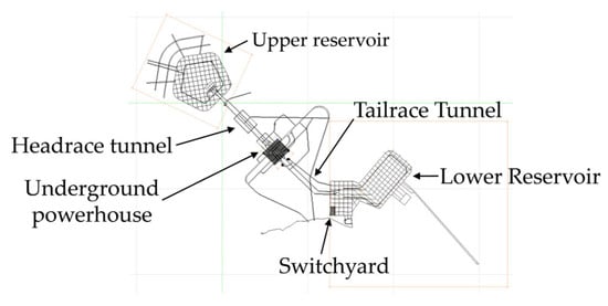
Figure 1.
Grounding Grid Model of the Pumped Storage Power Station.

Table 1.
Soil Subdivision Model of the Pumped Storage Power Station.
3.2. Seepage Field Simulation Model in COMSOL
In the finite element simulation software, multiphase transport in porous media is used to simulate the gas–water two-phase flow within the rock matrix. The Porous Media Flow module provides tools for modeling multiphase flow in porous media, where the number of phases can be set as two. The physical properties of the porous medium can be specified to simulate capillary action, water transport, or other transport phenomena. In this study, the Multiphase Transport in Porous Media module was employed to simulate large-scale seepage processes in rock media.
The VG-M model was selected for the porous medium. The seepage inlet was defined as a circular fully saturated water boundary, while infinite element domains were applied around the soil and at the ground surface. A water-phase outflow boundary was imposed at the outer edge of the infinite element domain, and the initial soil water content was set to a very low initial value. The fundamental parameters of the rock model are listed in Table 2.
Table 2.
Fundamental Parameters of the Rock Model.
The humidification (seepage-induced) effect of the pipeline grounding grid through seepage holes is influenced by factors such as aperture size and spacing. Figure 2 illustrates the distribution of the seepage field at the humidification boundary under the action of seepage holes with a diameter of 5 cm and a spacing of 5 m in a 50 m × 50 m area. As shown in the figure, the seepage effect is most pronounced in the vicinity of the seepage holes, while the influence of the seepage field gradually weakens with increasing distance from the holes. Moreover, since the overall size of the grounding grid is much larger than the aperture and spacing of the seepage holes, and the holes are arranged uniformly, the seepage effect of a 100 m × 200 m pipeline grounding grid can be reasonably used to characterize the large-scale seepage field, as shown in Figure 3.
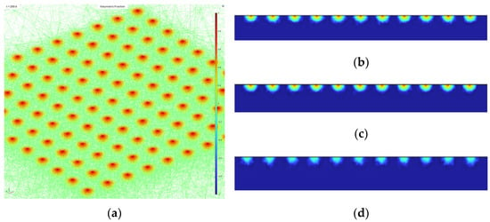
Figure 2.
Seepage Boundary with 5 cm Diameter and 5 m Spacing Holes in a 50 m × 50 m Domain. (a) 3D seepage field distribution at 200 d; (b) Seepage field distribution on the central cross-section at 200 d; (c) Seepage field distribution on the boundary cross-section at 200 d; (d) Seepage field distribution on the cross-section 1 m outside the humidified boundary at 200 d.
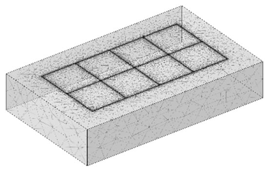
Figure 3.
Simulation Model of the Seepage Field in the Reservoir Bottom Bedrock.
4. Discussion
4.1. Influence of Infiltration Holes on Water Phase Transport
According to the simulation results, the upward migration component of the water phase can be reasonably neglected, which allows simplification of the boundary conditions at the upper surface in the seepage field model. Figure 4 illustrates the selection of the coordinate system plane. Figure 5 and Figure 6 illustrate the seepage effect of a 100 m × 200 m pipeline grounding grid, where the red regions represent regions with higher water content and the green regions represent the solid phase. The water phase within the bedrock exhibits an ellipsoidal distribution characterized by a thinner shape at both ends and a thicker middle section, indicating that gravity has a dominant influence on water migration. Correspondingly, the closer the location is to the infiltration holes in either the horizontal or vertical direction, the higher the water content.
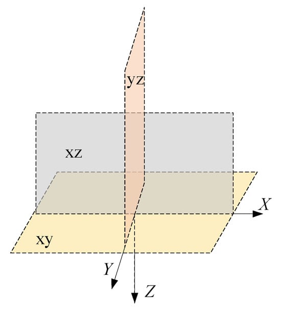
Figure 4.
Coordinate system plane.
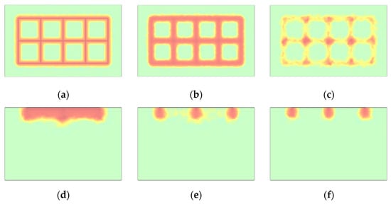
Figure 5.
The Distribution of Water Content within the Bedrock Medium after Six Months (with the Irrigation Boundary and the Center of the Bedrock as the Origin). (a) XY cross-section at 0 m; (b) XY cross-section at 8 m; (c) XY cross-section at 16 m; (d) YZ cross-section at 0 m; (e) YZ cross-section at 10 m; (f) YZ cross-section at 25 m.
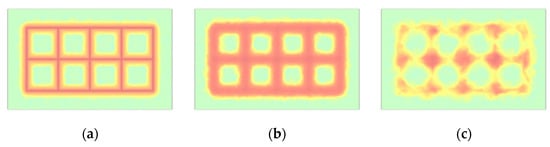
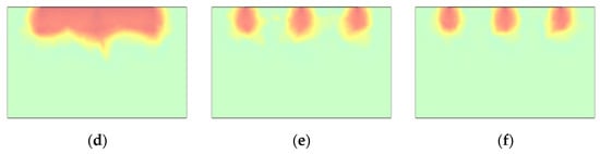
Figure 6.
Water Content Distribution within the Bedrock Medium after One Year. (a) XY cross-section at 0 m; (b) XY cross-section at 12 m; (c) XY cross-section at 24 m; (d) YZ cross-section at 0 m; (e) YZ cross-section at 10 m; (f) YZ cross-section at 25 m.
The multi-year moisture distribution and corresponding grounding resistance were obtained directly from COMSOL 6.0 simulations, which compute the seepage field at specific time points such as 0.5, 1, and 2 years. The resulting moisture contents were converted to bedrock resistivity distributions, which were then used in CDEGS to calculate grounding resistance for the same time points.
For internal validation, the seepage field around a single pipeline hole was examined to ensure physically reasonable water migration patterns, including downward flow and ellipsoidal wetting zones. Furthermore, the grounding resistance obtained from COMSOL 6.0 derived resistivity fields was compared with the equivalent layered soil model derived in CDEGS, confirming consistency between detailed seepage simulations and the grounding analysis. This indicates that the multi-year predictions are physically plausible and reliable.
4.2. Equivalent Method for Bedrock Resistivity Modeling
The resistivity–water content curve was incorporated into the model to obtain the bedrock resistivity distribution under the influence of the seepage field, as shown in Figure 7. Due to the presence of numerous unsaturated regions within the bedrock, directly discretizing the bedrock resistivity for calculation would complicate subsequent resistivity equivalence. Taking green sandstone as an example, the resistivity variation under different water contents can be divided into two stages, as illustrated in Figure 7. When the resistivity decreases to approximately 500 Ω·m, the resistivity reduction rate becomes significantly lower. Therefore, the bedrock resistivity is divided into two intervals. In Figure 8, the green regions correspond to equivalent resistivities below 500 Ω·m, while the remaining areas have resistivities above 500 Ω·m. For the subsequent equivalent calculation of geotechnical resistivity, the resistivity of the green regions is taken as 500 Ω·m, and that of the other regions is assigned as 38,000 Ω·m.
Figure 7.
Relationship Between the Resistivity ρ of Green Sandstone and Water Content θ.
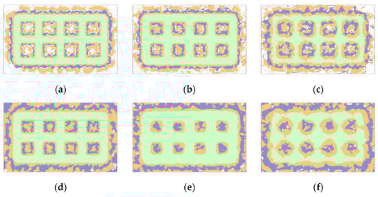
Figure 8.
Bedrock Resistivity Distribution (Green Area Resistivity Set to 500 Ω·m). (a) After 0.5 years at a depth of 5 m; (b) After 0.5 years at a depth of 7 m; (c) After 0.5 years at a depth of 15 m; (d) After 1 years at a depth of 0 m; (e) After 1 years at a depth of 14 m; (f) After 1 years at a depth of 23 m.
Based on the numerical results shown in Figure 7, the relationship between bedrock resistivity and water content exhibits a clear two-stage characteristic. A rapid decrease in resistivity is observed at low water contents, whereas further increases in water content result in only marginal resistivity reduction once the resistivity drops to approximately 500 Ω·m. This behavior indicates that the electrical resistivity of the bedrock approaches a lower bound under saturated conditions. Accordingly, a simplified equivalent resistivity model was adopted, where the resistivity of fully saturated bedrock was set to 500 Ω·m, and that of unsaturated (dry) bedrock was set to 38,000 Ω·m.
Using the moisture distribution around a single seepage hole shown in Figure 9, the affected rock volume was equivalently represented by an effective resistivity ρ1. For multiple seepage holes, the combined influence of individual seepage zones was further represented by an equivalent resistivity ρ2 and an equivalent thickness L. Using an equivalence approach [23], the ellipsoidal saturated zone is approximated as a rectangular region. Subsequently, the soil is discretized into blocks in CDEGS for simulation of the grounding impedance. Based on the principle of equal grounding impedance, the large-scale discrete saturated low-resistivity soil blocks are further equivalent to a layered soil model, forming a modified resistivity layer suitable for grounding analysis.
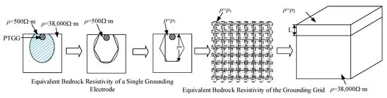
Figure 9.
Flowchart of the equivalent method for bedrock resistivity.
Through this staged and equivalence-based mapping procedure, the spatial water content distribution induced by seepage was effectively translated into a resistivity distribution, allowing the influence of controlled seepage on grounding performance to be quantitatively evaluated.
4.3. Effect of Seepage Hole Spacing on the Resistance Reduction in Pipeline-Type Grounding Grids
Based on the above equivalence method, seepage hole spacings of 1 m, 5 m, and 10 m were considered to construct the equivalent bedrock resistivity models, as summarized in Table 3. The corresponding grounding resistance calculation results are presented in Table 4.
Table 3.
Equivalent Model of Bedrock Low-Resistance Zones under Different Drip Hole Spacing Designs.
Table 4.
Calculated grounding resistance of the grounding system for different well-spacing design schemes.
As shown in Table 3, as the seepage hole spacing increases, the extent of the equivalent low-resistivity zone in the reservoir bedrock is significantly reduced, leading to a smaller overall decrease in bedrock resistivity. Consequently, the grounding system’s resistance reduction performance is weakened. When the drip hole spacing increases from 1 m to 10 m, significant differences in the first-year resistance reduction in the pipeline-type grounding grid are observed. This is because a higher density of seepage holes promotes earlier overlap of individual seepage zones, thereby forming a continuous low-resistivity region (approximately 500 Ω·m) within the bedrock. Under the 1 m spacing scheme, the bedrock moisture content in the first year is higher, resulting in a lower matric potential compared with the 10 m spacing design. As a result, during the second year, the incremental increase in bedrock moisture content under the 1 m spacing scheme becomes slower, and the corresponding rate of grounding resistance reduction decreases, eventually approaching a stable state.
Overall, the resistance reduction performance of the pipeline-type grounding grid decreases as the seepage hole spacing increases; however, the differences in resistance reduction gradually diminish with prolonged seepage duration. The trends in grounding resistance changes under the three drip hole spacing designs in Table 4 confirm this conclusion.
4.4. Effect of Seepage Hole Diameter on the Resistance Reduction Performance of Pipeline-Type Grounding Grids
A single seepage hole flow model was constructed within the porous medium, with hole diameters of 10 cm and 20 cm. The moisture content distribution along the axis directly below the seepage hole is shown in Figure 10. Comparison of the two cases indicates that, under a single-hole boundary condition, larger hole diameters result in faster downward infiltration of the wetting front. For the 20 cm hole, after 360 days of irrigation, the wetting front reached a depth of 8 m, and a distinct unsaturated zone remained within the bedrock beneath the seepage boundary.
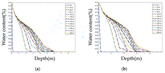
Figure 10.
Single-Hole Seepage Flow Distribution for Different Hole Diameters. (a) 10 cm Diameter Seepage Hole; (b) 20 cm Diameter Seepage Hole.
The thickness of the unsaturated zone within the bedrock also varies with hole diameter. After 360 days of seepage, the 20 cm hole produced a semi-ellipsoidal region with moisture content above 12%, having a minor axis of 0.5 m and a major axis of 0.8 m. In contrast, the 10 cm hole resulted in a smaller semi-ellipsoidal region with a minor axis of 0.2 m and a major axis of 0.35 m. In the single-hole seepage model, larger diameters facilitate faster water-phase movement, and the distribution pattern of the water phase remains consistent with the ellipsoidal characteristics described in Section 4.2.
Taking a spacing of 1 m, the groundwater saturation distribution in the bedrock was compared for seepage holes with diameters of 5 cm, 10 cm, and 20 cm. The corresponding equivalent bedrock resistivity models and grounding system resistances are listed in Table 5 and Table 6, respectively.
Table 5.
Equivalent Model of Bedrock Low-Resistance Zones for Different Hole Diameter Designs.
Table 6.
Calculated Grounding Resistance of the Grounding System for Different Hole Diameter Designs.
As shown in the tables, the differences in grounding resistance reduction among the pipeline-type grounding grids with different hole diameters are relatively small. This is because, relative to the large-scale rock–soil seepage field, the centimeter-scale hole diameters are negligible when compared with the tens-of-meters characteristic dimensions of the rock mass. When the spacing of the seepage holes is the same, the water-phase distribution retains a similar ellipsoidal pattern across different hole diameters, resulting in comparable equivalent low-resistivity regions at the base of the reservoir.
Although differences in the downward migration depth of the wetting front exist for the same seepage duration, Table 5 indicates that within six months, the wetting front under 5 cm and 10 cm holes does not exceed 10 m, causing a slightly larger difference in grounding resistance reduction during this period. However, after 1–2 years, the wetting front reaches depths beyond 10 m for all hole diameters, and the grounding resistance reduction effect becomes similar, gradually converging over time. Therefore, when the seepage hole spacing is fixed, the hole diameter exerts only a limited influence on the resistance reduction performance of the grounding grid.
4.5. Comparison with Conventional Grounding Resistance Reduction Methods
In conventional grounding design, grounding resistance reduction is commonly achieved through measures such as extending the grounding grid area, installing deep vertical electrodes, applying ground enhancement materials, using conductive concrete, or connecting the grounding system to naturally low-resistivity zones. Under ordinary soil conditions, these approaches can effectively improve current dissipation.
However, in reservoir-based pumped storage power stations with impermeable basin linings, the applicability of these methods is significantly constrained. The impermeable lining blocks current dissipation into the reservoir water and inhibits downward moisture migration into the underlying bedrock, which therefore remains dry and highly resistive. Consequently, extending the grounding grid beneath the lining or installing deep electrodes often results in marginal resistance reduction. Moreover, the long-term stability and environmental compatibility of chemical enhancement materials and conductive concrete are difficult to guarantee in large-scale hydraulic environments. A comparison of different grounding resistance reduction methods under impermeable basin conditions is presented in Table 7.
Table 7.
Comparison of Grounding Resistance Reduction Methods Under Impermeable Basin Conditions.
The PTGG proposed in this study is specifically designed for such impermeable basin conditions. Rather than relying solely on geometric expansion or material enhancement, the PTGG introduces controlled seepage beneath the impermeable lining, actively modifying the moisture state and resistivity of the bedrock within the primary current-dissipation region. In this sense, the PTGG serves as a targeted and complementary resistance reduction method for pumped storage power stations where conventional measures are insufficient.
4.6. Safety Considerations for Implementation in Water Environments
The proposed PTGG is designed as an integral component of the grounding system and does not carry operating current under normal conditions. Its primary function is to provide controlled seepage to modify the moisture state and resistivity of the underlying bedrock. Therefore, the introduction of water does not inherently increase electrical hazards during normal operation of the power station.
From an electrical safety perspective, the PTGG operates under the same grounding principles as conventional grounding grids. The grounding resistance, touch voltage, and step voltage must still satisfy the requirements specified in existing grounding design standards for hydropower and pumped storage power stations. The PTGG does not alter these safety criteria but enhances grounding performance by reducing bedrock resistivity.
During construction and maintenance, the seepage function of the PTGG can be fully isolated by shut-off valves, allowing the pipelines to remain in a dry or depressurized state. Standard safety procedures for working in wet environments, including electrical isolation, equipotential bonding, and controlled drainage, can be applied. In addition, the seepage process is characterized by low flow velocity and localized infiltration beneath the impermeable lining, which avoids the formation of exposed conductive water paths.
Overall, by combining controlled seepage operation, electrical isolation during maintenance, and compliance with existing grounding safety standards, the PTGG can be safely implemented in reservoir-based pumped storage power stations without introducing additional risks to personnel or equipment.
5. Conclusions
The present study addresses the issue of grounding grid performance degradation in pumped storage power stations caused by the use of insulating materials as the reservoir’s impermeable layer. A metal pipeline-type grounding grid with seepage holes, installed beneath the reservoir, is proposed. By developing a model for the pipeline-type grounding grid and analyzing its resistance reduction performance, the following conclusions are drawn:
(1) The pipeline-type grounding grid with seepage holes can reduce the soil resistivity beneath the reservoir’s impermeable layer, thereby lowering the grounding impedance. This approach can serve as an effective resistance reduction method in high-resistivity rock areas where conventional measures are insufficient.
(2) The large-scale soil model under the influence of seepage holes can be equivalently simplified into a layered soil model, with a saturated upper layer and a dry lower layer, facilitating grounding calculations.
(3) The resistance reduction effect of the pipeline-type grounding grid decreases as the spacing between seepage holes increases; however, the difference in reduction performance diminishes over time as seepage progresses.
(4) When the spacing of seepage holes is consistent, the hole diameter has negligible impact on the resistance reduction effect and can be disregarded.
(5) In practical design, the pipeline-type grounding grid must ensure both current dispersion and operational safety of the pumped storage power station grounding system during a controlled humidification process, while minimizing water consumption.
Author Contributions
W.D.: Conceptualization, Funding acquisition, Supervision; F.W.: Writing—review & editing, Formal analysis, Visualization; Y.L.: Writing—original draft, Methodology; W.W.: Conceptualization, Project administration; K.Z.: Conceptualization, Project administration; H.L.: Project administration, Supervision, Validation. All authors have read and agreed to the published version of the manuscript.
Funding
This research was funded by China Yangtze Power Co., Ltd. (4223020063) (Z422302057).
Data Availability Statement
The data that support the findings of this study are available from the corresponding author upon reasonable request.
Conflicts of Interest
Authors Wanqin Ding, Wendong Wang, and Kun Zhao were employed by the company China Yangtze Power Co., Ltd. The remaining authors declare that the research was conducted in the absence of any commercial or financial relationships that could be construed as a potential conflict of interest. The authors declare that this study received funding from China Yangtze Power Co., Ltd. The funder was not involved in the study design, collection, analysis, interpretation of data, the writing of this article, or the decision to submit it for publication.
Abbreviations
The following abbreviations are used in this manuscript:
| PTGG | Pipeline-Type Grounding Grid |
| VG | Van Genuchten |
References
- China Power Construction Group Co., Ltd. The first pumped storage power plant in Guangdong, Hong Kong and Macao Greater Bay Area to start construction in the “14th Five-Year Plan”. Pump Technol. 2022, 5, 57. [Google Scholar]
- Lu, Z.; Zhang, S.; Zhang, Z. Construction and operation status quo and development thinking of jointly operated pumped storage power station. Hydropower Pumped Storage 2022, 8, 103–108+115. [Google Scholar]
- Zhai, J.; Zhang, Y.; Zhang, Y. Leakage detection analysis of reinforced concrete basin in the upper reservoir of Shiliang Pumped Storage Power Station. Dam. Saf. 2022, 1, 27–31. [Google Scholar]
- Miao, K.; Bai, Z.; Huang, Y.; Huang, Y.; Su, Y. Research on Seepage Control of Jurong Pumped Storage Hydroelectric Power Station. Water 2022, 14, 141. [Google Scholar] [CrossRef]
- Ma, F.; Li, J.; Li, D.; Zuo, L.; Huang, J.; Fu, X. Research on seepage control technology of pumped storage power station reservoir basin. Water Conserv. Hydropower Technol. 2020, 51, 122–129. [Google Scholar]
- NB/T 35050-2023; Technical Specification for Earthing Design of Hydropower Plants. China Water & Power Press: Beijing, China, 2024.
- Elmashtoly, M.H.; Anis, H.I.; Emam, A. Mitigating Hazardous Potentials Near Pipelines Using Passive Grounding Grids. IEEE Access 2021, 9, 121957–121963. [Google Scholar] [CrossRef]
- Perng, J.-W.; Kuo, Y.-C.; Lu, S. Grounding System Cost Analysis Using Optimization Algorithms. Energies 2020, 11, 3484. [Google Scholar] [CrossRef]
- Li, Y.; Wang, F.; Teng, Y.; Cai, H.; Hu, S.; Wen, X.; Lan, L.; Liao, D.; Lu, H. Study on threshold value of gas generation current density of DC deep well grounding electrode. CSEE J. Power Energy Syst. (Early Access) 2025, 1–7. [Google Scholar]
- Muhammad, U.; Ahmad, N.N.; Nor, N.M.; Aman, F. Effect of Enhancement Material on the Performance of Ground Electrodes Under Impulse Conditions. IEEE Access 2025, 13, 106296–106310. [Google Scholar] [CrossRef]
- Daadaa, M.; Brettschneider, S.; Volat, C.; Simard, G. Numerical Investigation of the Use of Electrically Conductive Concrete-Encased Electrodes as Potential Replacement for Substation Grounding Systems. Energies 2023, 16, 4410. [Google Scholar] [CrossRef]
- Dou, B.; Liu, R.; Tu, Y.; Zhang, B. A Method for Calculating Grounding Resistance of Reinforced Concrete Foundation Grounding Systems. Energies 2022, 15, 4607. [Google Scholar] [CrossRef]
- Aiello, G.; Alfonzetti, S.; Rizzo, S.A.; Salerno, N. Thin Conductor Modelling Combined with a Hybrid Numerical Method to Evaluate the Transferred Potential from Isolated Grounding System. Energies 2019, 12, 1210. [Google Scholar] [CrossRef]
- Chen, S.; Shen, W.; Cao, W.; Miao, H.; Du, S.; Fan, Y. Research on Measures of Grounding Resistance Reduction for Substation Based on CDEGS. In Proceedings of the 2022 9th International Conference on Monitoring and Diagnosis, Kitakyushu, Japan, 13–18 November 2022; IEEE: New York, NY, USA, 2022; pp. 722–726. [Google Scholar]
- Li, R.; Zhai, H.; Jiang, C.; Zhu, W.; Li, X.; Wang, Z.; Wang, Y. A review of laboratory hydraulic fracturing experiments on shales. Geoenergy Sci. Eng. 2025, 254, 214028. [Google Scholar] [CrossRef]
- Van Genuchten, M.T. A closed-form equation for predicting the hydraulic conductivity of unsaturated soils. Soil Sci. Soc. Am. J. 1980, 44, 892–898. [Google Scholar] [CrossRef]
- Mualem, Y. A new model for predicting the hydraulic conductivity of unsaturated porous media. Water Resour. Res. 1976, 12, 513–522. [Google Scholar] [CrossRef]
- Standnes, D.C.; Ebeltoft, E.; Haugen, A.; Kristoffersen, A. Using the total chemical potential to generalize the capillary pressure concept and therefrom derive a governing equation for two-phase flow in porous media. Int. J. Multiph. Flow 2024, 181, 105024. [Google Scholar] [CrossRef]
- Chen, H.; Wang, J.; Luo, L.; Otto, S.; Davis, J.; Kuhlman, K.L.; Wu, Y. Electrical Resistivity Changes During Heating Experiments Unravel Heterogeneous Thermal-Hydrological-Mechanical Processes in Salt Formations. Geophys. Res. Lett. 2024, 51, 2024GL109836. [Google Scholar] [CrossRef]
- Yuan, J.; Li, Z. Complex mirror method for solving point source electric field problems in multilayer media. J. Tsinghua Univ. (Nat. Sci. Ed.) 1999, 5, 52–54. [Google Scholar]
- Pan, Z.; Li, J.; Liu, H.; Li, Z.; Zhang, L.; Wen, X. Multi-precision and multi-resolution calculation of layered soil grounding Green’s function. Chin. J. Electr. Eng. 2019, 39, 4451–4459. [Google Scholar]
- Pan, Z.; Zhang, L.; Tan, B.; Mei, G.; Wen, X. Simulation analysis of high voltage DC transmission inlet current distribution in AC grid. Power Syst. Autom. 2011, 35, 110–115. [Google Scholar]
- Li, Z.; Wu, G.; Fu, L.; Ren, X.; Cao, X. Simplified calculation of grounding resistance of soil-modeled ground network with double-layer structure. High Volt. Technol. 2008, 1, 45–48. [Google Scholar]


Disclaimer/Publisher’s Note: The statements, opinions and data contained in all publications are solely those of the individual author(s) and contributor(s) and not of MDPI and/or the editor(s). MDPI and/or the editor(s) disclaim responsibility for any injury to people or property resulting from any ideas, methods, instructions or products referred to in the content. |
© 2026 by the authors. Licensee MDPI, Basel, Switzerland. This article is an open access article distributed under the terms and conditions of the Creative Commons Attribution (CC BY) license.