Abstract
In the operation mode arrangement of bulk power systems, unreasonable reactive power injection data at nodes tend to result in power flow calculation non-convergence. Owing to the extremely high dimension of the variable space and the heterogeneous impacts of different variables on power flow convergence, it is imperative to accurately identify the key variables inducing non-convergence and provide physical justifications. For this purpose, this paper proposes a data-driven key variable identification and adjustment method: firstly, based on the blocking cut-set theory and the characteristic that the active unbalanced power ΔP of intermediate power flow exhibits opposite signs at the sending and receiving ends of the cut-set, a blocking cut-set identification method leveraging the characteristics of the active unbalanced power of intermediate power flow is developed; secondly, relying on the feature that the reactive unbalanced power ΔQ of intermediate power flow is less than zero, a key variable identification method based on the characteristics of the reactive unbalanced power of intermediate power flow is presented; finally, a key variable adjustment method grounded in the numerical value of ΔQ is proposed. The validity of the proposed approach was validated via simulated computations using both the IEEE 39 bus system and a practical bulk power system.
1. Introduction
Alongside the steady rise in renewable energy penetration levels and the increasing intricacy of system topologies, the operational modes of bulk power systems have grown progressively more diverse [1]. Against this backdrop, the phenomenon of power flow calculation non-convergence occurs frequently during the operation mode arrangement of bulk power systems, which has seriously restricted the efficiency of operation mode formulation. Typically, the active power injection data of nodes are determined based on historical data and expert experience; thus, it is generally recognized in engineering that the non-convergence of power flow calculation is primarily attributed to the unreasonable setting of reactive power injection data at certain nodes [2]. However, bulk power systems feature an extremely high-dimensional variable space, and different variables exert distinct impacts on power flow convergence. Failure to accurately identify the key variables triggering power flow non-convergence will lead to a reduction in the success rate and efficiency of convergence adjustment. Currently, power grid operators mostly rely on experience for key variable identification, which not only results in low identification accuracy but also lacks a clear physical basis [3]. Therefore, there is an urgent need for a method that can rapidly and precisely identify the key variables causing power flow non-convergence while providing a specific and unambiguous physical basis, thereby offering effective support for the power flow convergence adjustment of bulk power systems.
Existing relevant studies are mainly carried out from three perspectives: model-driven, knowledge-driven, and data-driven.
Model-driven methods identify key variables through the construction and solution of analytical models, offering prominent advantages such as significant dimensionality reduction and the provision of a solid physical basis. Optimization models were constructed and solved in References [4,5] to obtain the reactive power relaxation of nodes, based on which key variables were identified. The output reduction method was adopted in References [6,7,8] to recognize weak nodes or channels within the system, followed by the calculation of the sensitivity of each adjustment variable with respect to these weak nodes or channels. Key variables were then determined according to the computed sensitivity. An impedance ratio index was proposed in Reference [9] to identify voltage-weak regions, thereby enabling the determination of key variables. A virtual DC reactive power network model was established in Reference [10], and a local reactive power balance index was utilized for key variable identification. In Reference [11], PQ nodes were converted into PV nodes, the reactive power deficit index was calculated, and key variables were identified based on this index.
Knowledge-driven methods identify key variables through logical reasoning based on existing knowledge or experience, directly avoiding blind searches in high-dimensional spaces and providing experience-based physical foundations. Knowledge graphs were constructed from power flow adjustment experience in References [12,13,14], and logical reasoning was performed based on the embedded rules to identify key variables.
However, as the scale of the system continues to expand, the complexity related to model construction and solution analysis, together with the difficulty in knowledge base establishment and reasoning processes, rises remarkably; this significantly constrains their practical application in bulk power systems.
Data-driven methods do not require the construction of models or knowledge bases; instead, key variables are identified by directly mining and analyzing data insights. Based on deep reinforcement learning, a mapping relationship from system states to power flow adjustment actions was established in References [15,16,17,18,19,20] through the interactive learning between agents and the environment to identify key variables. However, with the expansion of system scale, they face the problems of an excessively high action space dimension and a lack of specificity in variable identification.
It is noteworthy that the iterative process of power flow calculation itself generates intermediate data rich in physical information. By mining and analyzing these iterative, intermediate data, key variables can be identified after eliminating a large number of irrelevant variables, and specific and clear physical bases can be provided. For instance, References [21,22] selected key variables based on the magnitude of iterative errors. Reference [23] utilized intermediate power flow data to calculate line transmission margins for identifying congested channels and determined key variables according to the type of congestion. Reference [24] constructed a susceptance deviation index to identify key variables based on the reactive unbalanced power and bus voltage magnitudes in intermediate power flow data. Existing methods have two limitations: first, they only focus on the numerical characteristics of iterative errors and fail to identify the physical structures that cause power flow non-convergence, resulting in a lack of specificity in variable identification; second, they only utilize intermediate power flow data to calculate relevant indicators, neglecting the errors between intermediate power flow data and given injection data. The root cause of the aforementioned limitations of existing methods lies in the fact that they stay merely at the level of numerical analysis of local nodes. They neither deeply explore the physical implications and spatial distribution characteristics of indicators nor conduct analyses from the perspective of system-wide power flow distribution.
In order to overcome the aforementioned limitations, this paper presents a data-driven approach for identifying and adjusting key variables, founded on the intermediate power flow data iteratively produced via the Newton–Raphson algorithm. The innovative aspects of this approach are outlined below:
- 1.
- A data-driven method is employed, with unbalanced power of intermediate power flow as the entry point. This approach effectively addresses the problems of insufficient specificity in variable identification and the ambiguous physical basis associated with existing data-driven methods, while avoiding the complexities of modeling and solution in model-driven methods, as well as the challenges in knowledge base construction for knowledge-driven methods.
- 2.
- Based on the blocking cut-set theory and the characteristic that the active unbalanced power ΔP of intermediate power flow exhibits opposite signs at the sending and receiving ends of the cut-set, a blocking cut-set identification method is proposed. This method enables the accurate identification of blocking cut-sets that cause power flow convergence failure.
- 3.
- With the aim of eliminating cut-set blocking, a key variable identification method is proposed by leveraging the characteristic that the reactive unbalanced power ΔQ of intermediate power flow is less than zero. The method identifies key nodes requiring reactive power compensation from both ends of the cut-set and their adjacent nodes, establishes a set of key variables, and automatically generates adjustment schemes based on the magnitude of ΔQ.
Simulation verification results in the IEEE 39 bus system and a practical bulk power system demonstrate that the proposed method can rapidly and accurately identify the key variables affecting the power flow convergence of operation modes while providing corresponding physical bases. Ultimately, it achieves reactive power compensation, offering effective references for power grid operators to identify reactive power compensation nodes and implement power flow convergence adjustments.
2. Principle of Blocking Cut-Set and Key Variable Identification Based on Characteristics of Unbalanced Power of Intermediate Power Flow
2.1. Blocking Cut-Set Theory and Concepts of Intermediate Power Flow
Based on the research reported in References [22,23,24], the blocking cut-set theory can be stated as follows: Under a given operation mode of bulk power systems, improper setting of node injection data is prone to result in insufficient voltage support at the nodes at both ends of one or more transmission cut-sets, thereby reducing the transmission limit of these cut-sets. When the active power to be transmitted exceeds this limit, power blocking occurs in the cut-set, leading to an imbalance of active power between the sending and receiving end systems and thus causing the power flow calculation of the given operation mode to fail to converge. Therefore, during power flow adjustment, the blocking cut-sets inducing power flow non-convergence can first be identified, followed by an analysis of the nodes at both ends of these cut-sets and their adjacent nodes (i.e., nodes directly connected to the nodes at both ends). Key nodes requiring reactive power compensation are then recognized from these nodes, thereby determining and adjusting the key variables.
When power flow calculation fails to converge, there must exist an iteration result with the smallest error during the iteration process of the Newton–Raphson method (e.g., the m-th iteration result shown in Figure 1), and the corresponding node injection data are closest to the given values. Therefore, this iteration result is referred to as the “closest intermediate power flow”. The closest intermediate power flow is the iterative result with the minimum error between the calculated node injection data and the given injection data, so its power flow distribution is highly consistent with that of the given operation mode. Therefore, it is easier to achieve accurate identification of blocking cut-sets and key variables based on these data. Unless otherwise specified in the following context, “intermediate power flow” specifically denotes the “closest intermediate power flow”.
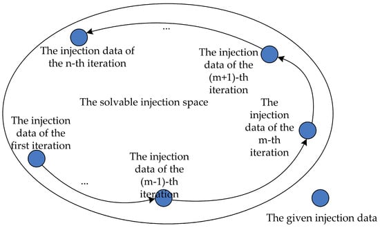
Figure 1.
Evolution diagram of injection data in iteration results.
Blocking cut-sets are recognized as the physical structure inducing power flow non-convergence, while intermediate power flows act as the key data carrier that contains key information on system adjustment. The correlative analysis between blocking cut-sets and intermediate power flows serves as the foundation for solving the key variable identification problem.
2.2. Definition of Unbalanced Power of Intermediate Power Flow
The result of the k-th iteration was designated as the closest intermediate power flow, and it was stipulated that the bus injected power is positive for inflow and negative for outflow. Accordingly, the following is derived:
where and are, respectively, denoted as the active and reactive unbalanced power of bus i; and represent the specified active and reactive injected power of bus i; and represent the active and reactive injected power of bus i in the closest intermediate power flow.
Node unbalanced power is formally defined as the discrepancy between prescribed injection data and the injection data derived from the closest intermediate power flow solution. An increased absolute value of this power quantity signifies a more pronounced difference between the two data sets at the corresponding node. Unless explicitly stated otherwise, the term “unbalanced power” employed in subsequent discussions specifically denotes “node unbalanced power.”
ΔP and ΔQ are observed between the intermediate power flow injection data and the given injection data, a phenomenon that essentially indicates the intermediate power flow resolves the issue of power flow non-convergence under the specified operation mode through generation scheduling adjustments and reactive power compensation measures. It is known from the blocking cut-set theory that when power flow calculation in bulk power systems fails to converge due to improper setting of node injection data, there must be at least one blocking cut-set in the system. To achieve convergence, the intermediate power flow needs to eliminate this blocking, thus requiring generation schedule adjustment and reactive power compensation. Among them, generation schedule adjustment is aimed at reducing the active power flowing through the blocking cut-set, while reactive power compensation is intended to improve the transmission limit of the cut-set. The synergistic effect of the two effectively eliminates the power blocking of the transmission cut-set and ultimately enables the convergence of the intermediate power flow. Based on this, the transmission cut-set (i.e., the blocking cut-set) for implementing generation schedule adjustment and the nodes for performing reactive power compensation can be located by exploring the information contained in ΔP and ΔQ, and the identification of key variables is achieved through their synergistic effect.
2.3. Characteristics of Active Unbalanced Power
2.3.1. Physical Meaning
In the intermediate power flow, if the active unbalanced power ΔP > 0, this indicates that the active power output of the corresponding bus is reduced or the active power demand is increased; if ΔP < 0, this signifies that the active power output of the bus is increased or the active power demand is decreased.
2.3.2. Spatial Distribution Characteristics
In intermediate power flow, unbalanced power is not uniformly distributed across the entire system but concentrated mainly in a small number of nodes. Taking the IEEE 9 bus system as a case study, non-convergent samples were constructed by increasing the load at Bus 7 and the active power output of the generator. The active unbalanced power under this condition (with a base value of 100 MVA) was marked on the topological diagram, and its spatial distribution characteristics are shown in Figure 2.
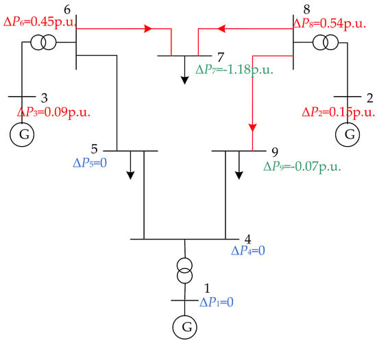
Figure 2.
Spatial distribution diagram of active unbalanced power of intermediate power flow.
For Line 8-7 illustrated in Figure 2, power blocking occurs. Along the transmission direction of its active power, the active unbalanced power ΔP8 at sending-end node 8 is positive (ΔP8 > 0), whereas the active unbalanced power ΔP7 at receiving-end node 7 is negative (ΔP7 < 0).
A positive ΔP8 at the sending end of Line 8-7 indicates that node 8 is required to reduce its active power output, while a negative ΔP7 at the receiving end implies that node 7 needs to lower its active power demand. In essence, the intermediate power flow reduces the active power flowing through the blocked line through the adjustment of generation schedules. Consequently, the buses subject to generation schedule adjustments are concentrated at both ends of the blocked line and their adjacent nodes.
It can be concluded that the spatial distribution characteristics of ΔP directly reflect the locations where generation schedule adjustments are implemented. The characteristic of opposite signs of ΔP at the sending and receiving ends serves as the core basis for identifying the blocking cut-set.
2.4. Characteristics of Reactive Unbalanced Power
2.4.1. Physical Meaning
In the intermediate power flow, if the reactive unbalanced power ΔQ > 0, this indicates that the reactive power demand of the bus is increased; if ΔQ < 0, this signifies that the reactive power demand of the bus is reduced, i.e., reactive power compensation has been implemented.
2.4.2. Spatial Distribution Characteristics
The spatial distribution of the reactive unbalanced power ΔQ is illustrated in Figure 3:
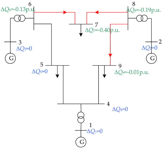
Figure 3.
Spatial distribution diagram of reactive unbalanced power of intermediate power flow.
When power blocking occurs on Line 8-7 as depicted in Figure 3, the reactive unbalanced power ΔQ at nodes 7 and 8 (situated at both ends of the blocking line) and their adjacent nodes 6 and 9 is typically negative.
A negative ΔQ corresponds to a reduction in the reactive power demand of the respective nodes. Essentially, the intermediate power flow increases the node voltage amplitude via reactive power compensation, thereby elevating the transmission limit of the blocking line. Consequently, reactive power compensation nodes are concentrated at both ends of the line and at their adjacent nodes.
From the above analysis, it can be deduced that the spatial distribution features of ΔQ mirror the direction of reactive power compensation, and nodes where ΔQ takes negative values correspond to the reactive power compensation nodes necessary for mitigating the blocking effect of the blocking cut-set.
3. A Key Variable Identification Method Based on the Unbalanced Power Characteristics of Intermediate Power Flow
3.1. A Blocking Cut-Set Identification Method Based on the Active Unbalanced Power Characteristics of Intermediate Power Flow
Intermediate power flow is mathematically characterized as iterative calculation results with errors exceeding the allowable range and is physically equivalent to convergent power flows achieved through reactive power compensation and generation schedule adjustment. The generation schedule adjustment implemented by the intermediate power flow is intended to reduce the active power flowing through the blocking cut-set, and this process generates active unbalanced power ΔP. Based on this, the identification of blocking cut-sets can be accomplished by analyzing the physical meaning and spatial distribution characteristics of ΔP. Specifically, the following inference is derived:
Under a given operation mode, for a transmission line experiencing power blocking, its sending-end bus generates positive active unbalanced power in the intermediate power flow, which serves to reduce its active power output; correspondingly, its receiving-end bus produces negative active unbalanced power to decrease its active power demand. Consequently, the buses situated at either end of the blocked line demonstrate the property of active unbalanced power with opposite polarities.
The proof process is as follows:
Let the line experiencing power blocking be denoted as Line i-j, with its maximum transmission power being Pmax. The specified injection data of nodes i and j are given by Equation (2):
where Pij and Pji are, respectively, defined as the active power transmitted through line i-j under the given operation mode; is defined as the total active power transmitted through lines connected to bus i under the specified operation mode, excluding the i-j transmission line; is defined as the total active power transmitted through lines connected to bus j under the specified operation mode, excluding the i-j transmission line.
In the intermediate power flow, the injection data of nodes i and j are shown in Equation (3):
where and are, respectively, denoted as the active power transmitted on line i-j in the intermediate power flow.
Given the condition that the non-convergence of power flow calculations is exclusively caused by power blocking on line i-j, with line losses disregarded, the following relationships hold:
Equations (2) and (3) were substituted into Equation (1), and the derived result can be obtained as follows:
In light of the above analysis, the inference is proven.
When the above inferences are extended to bulk power systems, it can be concluded that for a transmission cut-set with power blocking under a given operation mode, positive active unbalanced power is generated in the intermediate power flow by its sender-side system to reduce the active power output, while negative active unbalanced power is generated by the receiver-side system to lower the active power demand.
Based on the above analysis, a blocking cut-set identification method based on the active unbalanced power characteristics of intermediate power flow was proposed, with its procedure illustrated in Figure 4.
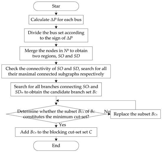
Figure 4.
Flow chart of the blocking cut-set identification method.
The topology of the system may be depicted as a graph , where N represents the set of nodes, and B stands for the set of branches. Based on the sign of ΔP at each node, N was divided into three pairwise disjoint subsets:
where i is designated as the node number; nodes satisfying ΔP > 0 are collectively designated as the set N+; nodes satisfying ΔP < 0 are collectively designated as the set N−; nodes satisfying ΔP = 0 are collectively designated as the set N0.
A node attribution mapping f: N0→{N+, N−} is introduced, such that for any , the following condition holds:
where j is defined as the node number, and Bij is designated as the branch between node i and node j.
Following mapping, the system nodes were merged into two complementary regions:
where SO refers to the region corresponding to active power output curtailment, and SD refers to the region corresponding to active power demand curtailment.
The sets of all maximal connected subgraphs of SO and SD are defined as and , respectively. The candidate branch set BC is defined as the set of all branches connecting SOl and SDm.
If a subset BCn of BC is the minimum cut-set between SO and SD in graph G, BCn is identified as a blocking cut-set in the system.
3.2. A Key Variable Identification Method Based on the Reactive Unbalanced Power Characteristics of Intermediate Power Flow
Reactive power compensation implemented by the intermediate power flow is intended to enhance the transmission limit of the transmission cut-set by increasing the voltage amplitude of nodes at both ends of the cut-set, and this process generates the reactive unbalanced power ΔQ. Based on this, combined with the identified blocking cut-sets, the identification of key variables can be achieved through an analysis of the physical meaning and spatial distribution characteristics of ΔQ. Specifically, the following inference is derived: for a line experiencing power blocking under a given operation mode, nodes at both ends of the line and their adjacent nodes typically produce negative reactive unbalanced power, which serves to increase the voltage amplitude of nodes at both ends of the line and thereby elevate the maximum transmission power of the line.
When the above inference is extended to bulk power systems, it can be concluded that, for a transmission cut-set with power blocking under a given operation mode, nodes at both ends of the cut-set and their adjacent nodes usually also generate negative reactive unbalanced power. Its function is to raise the voltage amplitude of nodes at both ends of the cut-set, thereby improving the maximum transmission power of the transmission cut-set. Thus, ΔQ < 0 can serve as an effective feature for identifying key variables.
Based on the aforementioned analysis, a key variable identification method grounded in the characteristics of the reactive unbalanced power of intermediate power flow is proposed.
Let BCn denote the identified blocking cut-set, and the node set D at both ends of the cut-set and the adjacent node set E are defined accordingly.
Thus, the key node set F is defined as follows:
The corresponding set of key variables is defined as Qcr:
4. A Key Variable Adjustment Method Based on Reactive Unbalanced Power of Intermediate Power Flow
After the identification of the key variable set, it is necessary to further determine the reactive power compensation quantity QC corresponding to each variable. It should be noted that the research focus of this paper lies in the identification of key variables; thus, only a brief discussion is provided regarding the determination of the reactive power compensation quantity.
The reason why the intermediate power flow can converge lies in the fact that power blocking in the transmission cut-sets—originally occurring under the given operation mode—is eliminated through reactive power compensation and generation schedule adjustments in the intermediate power flow. Therefore, relying exclusively on ∣ΔQ∣ for the compensation of key variables proves inadequate for guaranteeing power flow calculation convergence. Accordingly, the reactive power compensation quantity QC was proposed to consist of two components in this study:
- (1)
- Basic compensation component QC1: this was defined as the reactive power compensation implemented by the intermediate power flow relative to the given operation mode, i.e., QC1 = ∣ΔQ∣.
- (2)
- Equivalent compensation component QC2: this was defined as the additional reactive power compensation required after equivalently converting the impact of generation schedule adjustment on the blocking cut-set into the impact of reactive power compensation on the cut-set.
The specific calculation equation for the reactive power compensation quantity QC is given as follows:
Since the accurate analytical expression of QC2 is difficult to derive directly, it was set as a fixed value of QC2 = 0.20 p.u. It is explicitly noted that the value of QC2 simultaneously affects both the convergence speed and the total compensation quantity: if the value is too small, the convergence speed will be slow; if the value is too large, resource waste will be incurred. The value of QC2 is set to 0.20 p.u., which is determined by simulating the upper limit of the single-bank capacity of shunt capacitors. This value ensures the adjustment speed while avoiding the waste of reactive power compensation resources. It should be noted that the reasonable value of QC2 is closely related to the blocking degree of the blocking cut-set. The value of 0.20 p.u. is applicable to the operation scenarios configured in the case studies; however, when severe power blocking occurs in the cut-set, the value of QC2 needs to be appropriately increased to satisfy the convergence requirements.
Since a single adjustment is usually insufficient to re-converge the power flow, an iterative adjustment mechanism was established in this study. The iteration number was denoted as iter, with the maximum number of iterations set as itermax = 100; in each iterative adjustment, ΔQ was updated, and QC was recalculated until the power flow converged or iter = itermax.
The flow chart of the key variable identification and adjustment method is depicted in Figure 5.
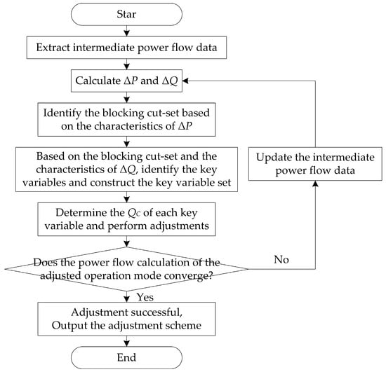
Figure 5.
Flow chart of critical variable identification and adjustment.
5. Case Study
5.1. IEEE 39-Bus System Case Study
Simulations were conducted using MATPOWER 6.0 within MATLAB R2023a, and the Newton–Raphson method was adopted as the power flow calculation method. Initially, the IEEE 39 bus system was selected as the simulation object, with the system base power set to 100 MVA.
To generate representative power flow non-convergent operation modes, this was achieved by constructing a heavy-load scenario with high-proportion renewable energy grid integration. First, on the basis of the original convergent power flow data pertaining to the system, random perturbations were imposed on the load values of each load node in Region 2 in accordance with the regional division of the original data, with the perturbation range constrained to 1.5–2.5 times the original load values. Subsequently, all thermal power units in Region 3 were replaced with renewable energy units, and node type conversion (i.e., adjustment from PV nodes to PQ nodes) was completed simultaneously. Random perturbations were also imposed on the output of the renewable energy units. Through the aforementioned steps, 2000 power flow calculation non-convergent operation modes were generated.
5.1.1. Test Results of Single Operation Mode
One of the operation modes was first selected for adjustment. After the intermediate power flow data were extracted, the power flow corresponding to the 14th iteration result was determined as the closest intermediate power flow based on the Emax index proposed in Reference [23]. Subsequently, the unbalanced power of each node was calculated in accordance with Equation (1). Based on the blocking cut-set identification method proposed earlier in this study, the identified blocking cut-sets are illustrated in Figure 6, and detailed information on each cut-set is provided in Table 1.
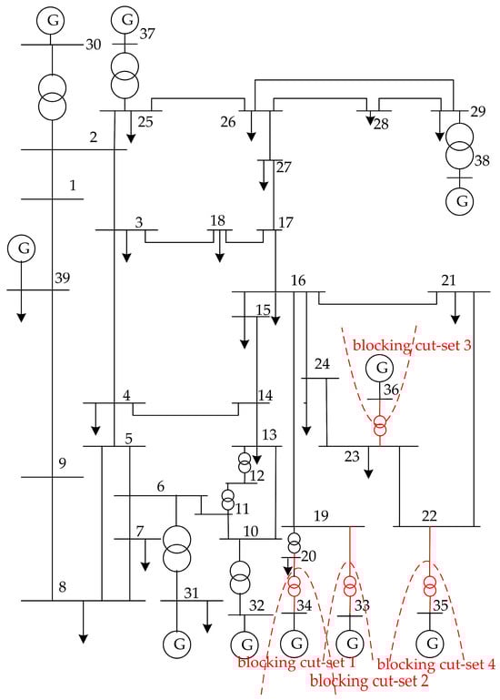
Figure 6.
Spatial distribution of blocking cut-sets in the IEEE 39 bus system.

Table 1.
Blocking cut-set information of the IEEE 39 bus system.
As indicated by the information of each blocking cut-set presented in Table 1, the absolute value of the active unbalanced power |ΔP| at both ends of blocking cut-set 1 was the largest; thus, it was prioritized for subsequent analysis.
To validate the efficacy of the method proposed in this study, a comparative assessment was performed across four distinct approaches, namely the method presented in this study, the method proposed in Reference [11], the method described in Reference [21], and the simplified variant of the proposed method based on non-blocking cut-sets. For the sake of consistency and fairness in comparison, the variable data adjustment process for all four methods was uniformly implemented using the adjustment strategy proposed herein. The results derived from the tests are presented in Table 2.
Table 2.
Test results for diverse methods for the IEEE 39 bus system based on a single operation mode.
The node conversion method proposed in Reference [11] identified key variables by converting PQ nodes into PV nodes, calculating the node reactive power deficit index, and subsequently leveraging this index. The approach presented in Reference [21] diagnosed the causes of power flow non-convergence through computing two indicators—voltage magnitude and the iterative decay ratio of phase angles—and correlating the magnitude relationships between these indicators. If the diagnosis result points to insufficient local reactive power support, key variables are identified based on the deviation of voltage magnitudes. The simplified method proposed in this study, which is grounded in non-blocking cut-sets, serves as the control group for the proposed method. These two methods exhibit a distinction solely in the type of cut-sets identified: the former recognizes non-blocking cut-sets, while the latter identifies blocking cut-sets.
Analysis combined with Table 2 reveals that the simplified method of this study, based on non-blocking cut-sets, failed after 100 iterative adjustments. This outcome stems from the fact that the blocking cut-sets responsible for power flow non-convergence were not identified by the method, which resulted in a lack of specificity in variable identification—equivalent to “blind compensation.” Consequently, the power blocking of cut-sets could not be effectively mitigated.
The number of key variables identified by the method proposed in Reference [11] was six more than that identified by the proposed method, with two of these variables located at both ends of the blocking cut-set (i.e., Q20 and Q35). Successful adjustment was achieved by both methods; however, the adjustment time consumed by the method in Reference [11] was 8.64 s longer than that of the proposed method. The reason for this lies in the fact that, although the reactive power deficit index adopted in Reference [11] can effectively identify “reactive power-deficient nodes”, this index only focuses on the reactive power demand of the nodes themselves and fails to consider the topological positional relationship between these “reactive power-deficient nodes” and the blocking cut-set. As a result, the identification results include nodes far from the blocking cut-set. Reactive power compensation implemented on such nodes can improve the local voltage level but cannot guarantee the elimination of power blocking in the cut-set, making adjustments to these nodes unnecessary. Additionally, the long calculation time required for the node recovery process collectively leads to the prolonged adjustment time of the method in Reference [11].
The number of key variables identified by the method proposed in Reference [21] was 19 more than that identified by the proposed method, and the adjustment failed. The reason is that key variables in Reference [21] were only identified through the numerical values of correction amounts of state variables. The blocking cut-sets that induce power flow non-convergence were not identified, nor was the topological positional relationship between variables and blocking cut-sets considered. This results in most of the identified variables being those “with large voltage magnitude deviations but irrelevant to eliminating cut-set blocking”. After 100 cyclic iterative adjustments, the power flow still failed to converge, and the adjustment was thus determined to be unsuccessful.
In contrast, the method proposed herein took the unbalanced power of intermediate power flow as the entry point. Not only were the numerical characteristics of this unbalanced power considered, but an in-depth analysis of its physical implications and spatial distribution characteristics was also conducted. Blocking cut-sets were accurately identified through the aforementioned characteristics, and key variables were subsequently recognized from both ends of the identified cut-sets. Notably, power flow convergence was successfully achieved by adjusting only two variables.
5.1.2. Test Results of Multiple Operation Modes
Similarly, two thousand non-convergent operation modes were utilized to conduct comparative tests on the proposed method, the method presented in Reference [11], the method reported in Reference [21], and the simplified variant of the proposed method based on non-blocking cut-sets (with the test results summarized in Table 3). Two evaluation indicators were adopted to assess the performance of each method, as follows:
Table 3.
Test results for diverse methods for the IEEE 39 bus system based on multiple operation modes.
- (1)
- Adjustment success rate: this is defined as the ratio of the number of operation modes that achieved power flow convergence after adjustment by the respective method to the total number of generated non-convergent operation modes.
- (2)
- Average adjustment time: this is defined as the average time required for each operation mode in the set of converged operation modes (post-adjustment) to transition from the initial non-convergent state to the power flow convergent state.
It can be observed from Table 3 that the adjustment success rate of the proposed method was 0.15%, 20.50%, and 12.98% higher than those of the method in Reference [11], the method in Reference [21], and the simplified variant of the proposed method based on non-blocking cut-sets, respectively. In terms of the average adjustment time, it was reduced by 27.73 s, 8.72 s, and 4.64 s compared with the aforementioned methods, respectively. It can thus be concluded that first identifying the blocking cut-sets that cause power flow non-convergence and then conducting key variable identification with the goal of eliminating cut-set blocking enhances the specificity of variable identification, thereby improving the success rate and efficiency of power flow adjustment. However, owing to the limited scale of the system, the performance improvement achieved by the proposed method failed to be fully exhibited.
5.2. Practical Bulk Power System Case Study
In order to confirm the efficacy of the proposed method within bulk power systems, a practical bulk power system was additionally employed as the simulation object. This system contains 2896 nodes, 4458 transmission lines (including transformers), and 352 generators (21 of which are renewable energy generators) and was divided into 71 regions. The system base power was set to 100 MVA.
Drawing on the initial convergent power flow data of the system, in accordance with the regional division of the original data, random perturbations were imposed on the load values of each load node in Regions 1–14, with the perturbation range constrained to 2.0–2.5 times the original load values. Meanwhile, the outputs of renewable energy generators were subjected to random perturbations. Through the aforementioned steps, 1000 non-convergent operation modes were generated to conduct comparative tests on the proposed method, the method in Reference [11], the method in Reference [21], and the simplified variant of the proposed method based on non-blocking cut-sets, with the test results presented in Table 4.
Table 4.
Test results for diverse methods for a practical bulk power system.
It can be observed from Table 4 that the adjustment success rate of the proposed method was 39.10 percentage points and 29.70 percentage points higher than those of the method in Reference [11] and the method in Reference [21], respectively. In terms of the average adjustment time, it was reduced by 177.96 s and 199.62 s compared to the two aforementioned methods, respectively. Among these, the adjustment success rate of the simplified variant of the proposed method based on non-blocking cut-sets was zero. The results demonstrate that in bulk power systems, the proposed method exhibits significant advantages both in terms of adjustment success rate and average adjustment time. In comparison to conventional methods, the presented method is grounded in the unbalanced power of intermediate power flow and is less affected by the adverse impacts brought about by the expansion of system scale. This method can offer effective support to the adjustment of power flow convergence for operation modes in bulk power systems.
6. Conclusions
Aiming at the problems with identifying the key variables and ambiguous physical basis when power flow calculation fails to achieve convergence in the operation mode of bulk power systems, a method for identifying and adjusting key variables based on the characteristics of the unbalanced power of intermediate power flow is proposed and verified. Its main innovations are as follows: taking the unbalanced power of intermediate power flow as the entry point, combined with the blocking cut-set theory, blocking cut-sets are accurately identified through the characteristic that the active unbalanced power ΔP exhibits opposite signs at the sending and receiving ends; key variables are then identified from the nodes at both ends of the cut-set and their adjacent nodes by leveraging the characteristic that the reactive unbalanced power ΔQ is less than zero; finally, adjustment schemes are generated based on the numerical value of ΔQ. This method not only avoids the limitations of model-driven methods (such as complex modeling and solution processes) and knowledge-driven methods (such as challenges in knowledge base construction) but also addresses the problems of the insufficient specificity in variable identification and ambiguous physical basis existing in current data-driven methods. It can quickly guide power grid operators to identify nodes requiring reactive power compensation and provide corresponding reactive power compensation schemes, greatly improving the efficiency of operation mode arrangement and thus possessing significant engineering application value.
It should be noted that the proposed method relies on the iterative intermediate data generated by the Newton–Raphson method. When there is an excessive deviation between these data and the given injection data of the operation mode, the accuracy of blocking cut-set identification will decrease, thereby affecting the precision of key variable identification. Meanwhile, the equivalent compensation component in the reactive power compensation quantity is adopted as a fixed value and has not been adaptively determined. Future research will focus on the following two aspects: first, exploring data analysis methods under the condition of excessive deviation of intermediate power flow data; second, conducting research on the adaptive adjustment method of key variables to realize the dynamic adjustment of QC2 value based on the blocking degree of the blocking cut-set. The blocking degree of the cut-set is characterized by the absolute value of the active power imbalance ΔP at both ends of the blocking cut-set, so as to further improve the adjustment efficiency and formulate scientific and reasonable adjustment schemes.
Author Contributions
Conceptualization, Y.Z.; methodology, Y.Z. and Y.F.; validation, Y.F.; writing—original draft, Y.Z. and Y.F.; writing—review and editing, Y.Z. and Y.F. All authors have read and agreed to the published version of the manuscript.
Funding
This research received no external funding.
Data Availability Statement
The original contributions presented in this study are included in the article. Further inquiries can be directed to the corresponding author.
Acknowledgments
Sincere gratitude is extended to my supervisor for the meticulous guidance and selfless assistance provided throughout the entire research process. Furthermore, heartfelt thanks are expressed to the anonymous reviewers for their professional review comments and valuable revision suggestions, which have played a pivotal role in enhancing the overall quality and academic rigor of this manuscript. Moreover, sincere appreciation is conveyed to the editorial board of the journal for the efficient organization and robust support rendered to ensure the rigorous presentation of the academic findings herein. Finally, high respect is paid to the academic peers in the related fields for their invaluable contributions to the advancement of this research area.
Conflicts of Interest
The authors declare no conflicts of interest.
References
- Das, T.; Roy, R.; Mandal, K.K. Impact of the penetration of distributed generation on optimal reactive power dispatch. Prot. Control Mod. Power Syst. 2020, 5, 332–357. [Google Scholar] [CrossRef]
- Chen, H. Research on Reactive Power Adjustment Method of Planning Power Flow Based on Minimizing Power Flow. Master’s Thesis, North China Electric Power University, Beijing, China, 2019. [Google Scholar]
- Jin, H.; Song, J. Convergence adjustment method of similar power flow based on voltage stability. Jilin Electr. Power 2022, 50, 19–24. [Google Scholar]
- Yan, Z.; Fan, X.; Zhao, W.; Xu, X.; Fan, J.; Wang, Y. Improving the convergence of power flow calculation by a self-adaptive Levenberg-Marquardt method. Proc. CSEE 2015, 35, 1909–1918. [Google Scholar]
- Zeng, H.; Guo, Q.; Zhou, Y.; Sun, H.; Liu, M.; Yang, Y. Reactive power adjustment method of non-convergent power flow for power system operation mode calculation. Power Syst. Prot. Control 2022, 50, 1–12. [Google Scholar]
- Li, M.; Chen, J.; Chen, H.; Duan, X. Load flow regulation for unsolvable cases in a power system. Autom. Electr. Power Syst. 2006, 30, 11–15. [Google Scholar]
- Hong, F. Research on Power Flow Automatic Adjustment Methods in Power System. Doctoral Dissertation, Huazhong University of Science and Technology, Wuhan, China, 2011. [Google Scholar]
- Wang, T.; Tang, Y. An unsolvable power flow adjustment method for weak power grid based on transmission channel positioning and deep reinforcement learning. Electr. Power Syst. Res. 2022, 210, 108050. [Google Scholar] [CrossRef]
- Li, J. Research and Implementation of Automatic Power Flow Adjustment Technology. Master’s Thesis, North China Electric Power University, Beijing, China, 2022. [Google Scholar]
- Zhang, S.; Zhang, D.; Huang, Y.; Li, W.; Chen, X.; Tang, Y. Research on automatic power flow convergence adjustment method based on modified dc power flow algorithm. Power Syst. Technol. 2021, 45, 86–97. [Google Scholar]
- Li, Z.; Han, Y.; Su, Y.; Sun, X.; Huang, H.; Chen, J. A convergence adjustment method of power flow based on node type switching. Autom. Electr. Power Syst. 2015, 39, 188–193. [Google Scholar]
- Wen, J.; Chen, X.; He, F.; Yang, Y.; Liu, M.; Xie, D. An artificial intelligence adjustment method of large-scale power flow based on knowledge-driven. In Proceedings of the 2021 China International Conference on Electricity Distribution, Shanghai, China, 6–9 April 2021; pp. 441–445. [Google Scholar]
- Wen, J.; Chen, X.; Zhao, M.; Lu, S.; Li, F.; Xu, X. Artificial intelligent adjustment method of power flow convergence for large-scale power grid based on knowledge graph. In Proceedings of the 12th International Conference on Renewable Power Generation, Shanghai, China, 14–15 October 2023; pp. 615–620. [Google Scholar]
- Liu, H.; Wen, J.; Chen, X.; Huang, H.; Wang, T.; Wang, H.; Huang, Y.; Tang, Y.; Yang, D. Knowledge modeling method for simulation analysis of large-scale power system and their application in automation adjustment of power flow driven by knowledge. Proc. CSEE 2023, 43, 1843–1855. Available online: https://link.cnki.net/doi/10.13334/j.0258-8013.pcsee.220719 (accessed on 22 January 2026).
- Xu, H.; Yu, Z.; Zheng, Q.; Hou, J.; Wei, Y. Improved deep reinforcement learning based convergence adjustment method for power flow calculation. In Proceedings of the 16th IET International Conference on AC and DC Power Transmission, Online, 2–3 July 2020; pp. 1898–1903. [Google Scholar] [CrossRef]
- Hu, W.; Mi, N.; Wu, S.; Zhang, H.; Hu, Z.; Zhang, L. Intelligent adjustment for power system operation mode based on deep reinforcement learning. iEnergy 2024, 3, 252–260. [Google Scholar] [CrossRef]
- Yan, F. Research on Ill Conditioned Power Flow Automatic Adjustment Strategy Based on Deep Reinforcement Learning. Master’s Thesis, North China Electric Power University, Beijing, China, 2021. [Google Scholar]
- Xu, H. Deep Reinforcement Learning Based Auxiliary Computing Method for Power System Operation State. Master’s Thesis, China Electric Power Research Institute, Beijing, China, 2020. [Google Scholar]
- Liu, J. Research on Intelligent Adjustment Algorithm of Power Grid Operational Planning Based on Deep Reinforcement Learning. Master’s Thesis, Sichuan University, Chengdu, China, 2021. Available online: https://link.cnki.net/doi/10.27342/d.cnki.gscdu.2021.003578 (accessed on 22 January 2026).
- Wang, T.; Tang, Y.; Guo, Q.; Huang, Y.; Chen, X.; Huang, H. Automatic adjustment method of power flow calculation convergence for large-scale power grid based on knowledge experience and deep reinforcement learning. Proc. CSEE 2020, 40, 2396–2406. [Google Scholar]
- Peng, H.; Li, F.; Yuan, H.; Bao, H. Power flow calculation and condition diagnosis for operation mode adjustment of large-scale power systems. Autom. Electr. Power Syst. 2018, 42, 136–142+159. [Google Scholar]
- An, J.; Song, J.; Ge, W. Convergence identification and adjustment method of power flow calculation for large-scale power system. Electr. Power Autom. Equip. 2020, 40, 103–109. [Google Scholar]
- Mu, G.; Zhou, Y.; Yang, M.; Chen, J. A diagnosis method of power flow convergence failure for bulk power systems based on intermediate iteration data. Energies 2023, 16, 3540. [Google Scholar] [CrossRef]
- Qi, M.; An, J.; Li, X. Identification and adjustment method of non-convergence key nodes in power flow calculation based on iterative injection of reactive power and voltage. Jilin Electr. Power 2025, 53, 14–18. Available online: https://link.cnki.net/doi/10.16109/j.cnki.jldl.2025.02.008 (accessed on 22 January 2026).
Disclaimer/Publisher’s Note: The statements, opinions and data contained in all publications are solely those of the individual author(s) and contributor(s) and not of MDPI and/or the editor(s). MDPI and/or the editor(s) disclaim responsibility for any injury to people or property resulting from any ideas, methods, instructions or products referred to in the content. |
© 2026 by the authors. Licensee MDPI, Basel, Switzerland. This article is an open access article distributed under the terms and conditions of the Creative Commons Attribution (CC BY) license.