Abstract
In flexible AC/DC microgrids, a variety of non-traditional power equipment are in operation, such as AC/DC interlinking converters. Moreover, due to the influence of interlinking converters, short-circuit fault characteristics in microgrids are much different from those in traditional distribution networks, which makes existing protection methods have poor adaptability. This paper introduces an active power variable-based differential protection method, which is suitable for various non-traditional power equipment. While in normal operation or during an external fault state, internal active power losses are rather minimum, resulting in nearly zero power difference between equipment terminals. However, during an internal fault state, the active power difference between terminals becomes extremely large, which can be adopted as protection criteria. The selectivity and rapidity are verified by simulation cases, and the aforementioned method is applicable to various non-traditional equipment, such as single-phase AC/DC converters, three-phase AC/DC converters, etc.
1. Introduction
A flexible AC/DC hybrid microgrid will use large amounts of adjustable resources on more buses and over wider areas compared to traditional microgrids. It will not only achieve optimal coordination among these internal sources, loads, and storage but also support the superior-level distribution grid in better operation. It is also one of the key techniques of future smart distribution grids, and the advantages include friendly integration of new energy power sources, reduction in transmission and transformation losses, improvement on load supply performance, and enhancement to power quality, which represent the trend of distribution grids [1,2,3].
A typical topology of a flexible AC/DC hybrid microgrid is shown in Figure 1, which mainly consists of an AC sub-microgrid, a DC sub-microgrid, and an interlinking converter (ILC). In this case, AC and DC sub-grids are integrated, combining the advantages of both AC and DC microgrids: firstly, it may eliminate unnecessary intermediate AC/DC power conversion, thereby improving total efficiency; secondly, the energy from different sub-grids serve as backup to each other, enhancing the reliability of the hybrid microgrid. Therefore, it will play a key role in the development of future active grids [4,5,6,7].
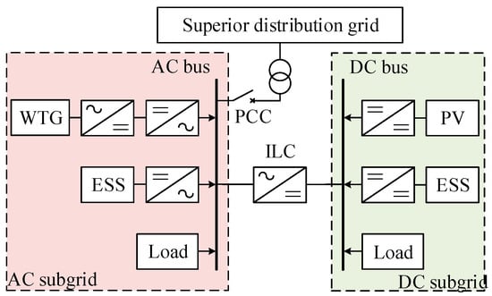
Figure 1.
Topology of flexible AC/DC hybrid microgrid.
However, while improving flexibility and resilience, the fault characteristics of the system also tend to become more complex. After a short circuit fault occurs in a flexible AC/DC distribution microgrid, its fault characteristics are significantly different from traditional distribution networks due to the rapid control of power electronic converters, which poses a serious challenge to existing protection schemes and has obvious adaptability issues [8,9]. Due to the current-limitation control of relevant power electronic-based equipment, characteristics of short-circuit current are not prominent, leading the amplitude to not reach the preset value of traditional current protection. Even high-performance traditional differential current protection may suffer from issues such as reduced sensitivity. Nonlinear characteristic may cause coupling interference between different power electronic-based equipment, leading to nonlinear voltage changes and affecting the accuracy of low-voltage protection actions. The integration of distributed power sources will lead to bidirectional power flow, causing malfunctions in directional protection module. Additionally, the coexistence of AC and DC equipment in a flexible AC/DC hybrid microgrid presents challenges with non-universal protection strategies [10,11,12]. In summary, despite these advantages of hybrid microgrid, the existing protection solutions for the flexible AC/DC microgrid are no longer suitable for the impact of a high proportion of distributed power sources, so it is very urgent to develop new relay protection schemes.
For DC microgrids, a method for diagnosing DC circuit faults using convolutional neural networks to extract signal features is proposed in [13]; convolutional neural networks and long short-term memory networks to troubleshoot faults in DC-DC converters within the DC grid is adopted in [14]; and fault detection in overhead flexible DC grids using artificial neural networks is implemented in [15]. For AC microgrids, [16] introduces a solid-state short-circuit current blocker based on an LC series resonant circuit, which offers advantages such as a simple structure, fast response, and strong overcurrent capability of equipment; ref. [17] proposes a detection criterion based on the small half-wave characteristics of short-circuit currents; and ref. [18] introduces voltage correction factors and gradient indices to enhance the sensitivity of anti-time-limit overcurrent protection. Currently, research on the protection of flexible AC/DC microgrid is rather limited, especially the overall solutions, including current protection, adaptive protection, distance protection, and intelligent algorithm protection [19,20], while some references such as [21] propose a new adaptive AC overvoltage protection scheme for AC/DC hybrid systems. There is still a lack of a universal protection principle that can uniformly deal with various non-traditional fault characteristics and is not limited by active and passive components for the new type of microgrid with mixed AC/DC and different component characteristics.
To cope with various fault scenarios during actual operation of a hybrid system and to enhance the existing protection methods, this paper proposes a differential protection method based on active power variable that is suitable for non-traditional power equipment. The rapid control function of switching devices is considered, while the electrical quantities of non-traditional fault characteristics is avoided. So, in addition to being applicable to flexible AC/DC microgrids, this protection method is also widely applicable to traditional AC and DC power grids. The advantages include versatility in AC and DC equipment, single or three-phase AC systems, and both active and passive equipment, being suitable for traditional single AC or single DC power grids, being unaffected by the internal characteristics of the equipment, being compatible with both fast and backup protection without the need for additional power direction elements; and not requiring multiple protection principles based on different equipment, thus simplifying the protection configuration.
2. Instantaneous Injection Power Characteristics
This section will first briefly describe the principle of traditional current differential protection and then introduce the principle of power differential protection in detail.
Traditional differential protection is a primary method used in AC power grids to protect critical equipment, such as transformers, buses, and generators. Its core principle involves comparing the vector sum of currents at each end of the protected device in real time. During normal operation, the inflow and outflow currents are equal, resulting in a vector sum close to zero. If an internal short circuit occurs, the current difference will significantly increase, triggering the protection device to quickly disconnect the faulty circuit or fault equipment. The advantages of this protection method include rapid response, high sensitivity, and strong reliability. It can effectively distinguish between internal equipment faults and external fault or abnormal circumstances, preventing mistake trips. Additionally, it always uses technologies like optical fiber communication to overcome the impact of long-line capacitive currents, ensuring precise protection.
The traditional current differential protection is usually a two-terminal electrical quantity protection, and the protected area is just the range between bus bars on both sides of the equipment. The protection principle is shown in Figure 2. If the protected equipment is in normal circumstances or a fault occurs at point k1 outside the protected area, there is
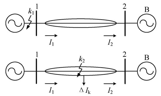
Figure 2.
Principle diagram of traditional current differential protection.
If fault occurs at point k2 in the protection area, then there is
However, electrical power is selected as differential protection criterion in this paper, primarily because it more directly reflects abnormal circumstances in energy transmission. Differential power is determined by both voltage and current. Compared to only differential current, differential power is more sensitive to high-impedance faults within equipment, such as light turn-to-turn short circuits in coil. These faults may cause weak current rise but significant power losses, leading to a larger power difference to normal state. Additionally, differential power can effectively suppress false differential currents caused by oscillations in power grids or in current transformer saturation, thereby enhancing the selectivity and reliability of protection trips in complex operating conditions.
Similarly, power differential protection can be achieved by comparing only active power differences between the input and output terminals of the been protected equipment in real time. During normal operation, the equipment’s active power is nearly balanced, resulting in minimal power difference; however, if an internal fault occurs, the power difference will significantly increase, possibly triggering the protection device to quickly isolate the fault by breaker. This protection method is particularly suitable for flexible AC/DC microgrids with high impedance faults or low-load conditions, effectively complementing current differential protection. It also offers advantages in conventional AC grid oscillations and interference from current transformer saturation.
Power differential protection is two-terminal electrical quantity protection, and the protected area is just the range between the bus bars on both sides of the element. The protection principle is shown in Figure 3. If the protected element is normal or the fault occurs at point k1 outside the protected area, then there is
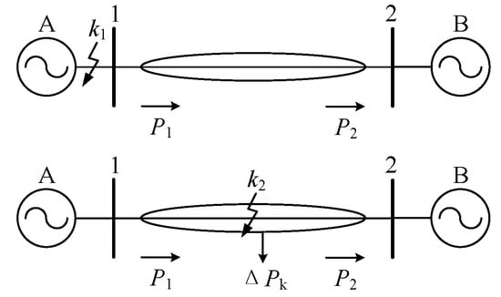
Figure 3.
Schematic diagram of power differential protection principle.
If the fault occurs at point k2 in the protection area, then there is
Power differential protection can be used as the primary protection in specific scenarios, as it can directly detect abnormal changes in energy transmission and quickly isolate faults. In complex systems, it can be configured in conjunction with current differential protection to form multiple primary protections or complement each other. In rare cases, it can serve as a backup protection to enhance redundancy. The specific configuration should be determined based on the type of equipment, fault characteristics, and system protection strategies.
For AC systems, the zero-sequence current generated by an unbalanced ground fault can lead to inaccurate power values. Therefore, this paper focuses on the positive sequence AC power derived from positive sequence voltage and current. The following section will analyze the actual power difference characteristics of the flexible AC/DC microgrid equipment under normal conditions (including out-of-zone faults) and in-zone faults separately.
2.1. Normal (Out-of-Zone Fault) Condition
When equipment are operating normally or in the event of external faults, ideally, the steady-state value of the power difference ΔP between the two terminals should approach zero. However, in actual grid operations, when equipment are either normal or in the event of external faults, the power on both terminals is not balanced. The main factors causing the deviation from zero include internal characteristics of the equipment, such as power losses and transformer excitation surges; power electronic equipment introducing non-sinusoidal voltage and current, particularly PWM control leading to unequal power factors, power fluctuations, and harmonics; different or asynchronous control strategies on AC and DC sides, such as in multi-level interconnected converters; voltage fluctuations or distortions on AC and DC sides; and the dynamic response of the converter system, such as during system switching or startup.
Specifically, when the flexible AC/DC microgrid equipment is operating normally or in the event of a fault outside the zone, the power difference ΔP between the two terminals of the component is a certain value due to internal characteristics and other factors. ΔP = P1 − P2 = ΔP * (t) is a time-varying variable, and its overall value is relatively rather small compared to the case of a fault within the zone. The time-varying characteristics of ΔP * (t) differ among different equipment. Then, DC lines, transformers, and interconnected converters will be use as examples to illustrate their ΔP * (t).
In the steady state of a DC line, ΔP* (t) changes very little and can be approximated as constant, that is, it is independent of time t, and due to power loss and other reasons, ΔP* (t) eventually tends to a certain value, that is, ΔP* (t) = KL (KL is a certain value).
When a transformer is energized under no-load conditions, the resulting inrush current is essentially a sudden increase in excitation current due to core saturation. This energy is primarily used to establish the magnetic field, making the primary-side power predominantly reactive, with only a minimal active component (mainly from active losses on the primary side, such as winding resistance). When the secondary side is no-load, the current is nearly zero, so the power difference is approximately equal to the primary-side excitation power, i.e., ΔP ≈ 0, ΔQ ≈ U × I inrush current × sinθ (where θ is the phase difference between voltage and inrush current, close to 90°). The active power difference on both sides differs significantly from that during a short-circuit fault. Additionally, the inrush current contains a large amount of harmonics, which further reduces the effective value of the actual active power difference. Therefore, the active power difference on both terminals can serve as a basis for differential protection to distinguish faults from inrush currents. The specific function expression of the inrush current process ΔP* (t) can be fitted using multiple discrete data points. In steady state, ΔP* (t) changes very little and can be considered constant, independent of time t. Due to power losses and other factors, ΔP* (t) eventually stabilizes at a certain value, i.e., ΔP* (t) = KT (KT is a constant value).
In steady state, the change in ΔP* (t) is very small and can be approximated as constant, that is, it is independent of time t, and due to power loss and other reasons, ΔP* (t) eventually tends to a certain value, that is, ΔP* (t) = KVSC (KVSC is a certain value).
Considering that a flexible AC/DC distribution microgrid involves a variety of equipment such as a new energy power supply, it is necessary to comprehensively study its various characteristics and constantly improve the protection method to ensure that the system can be safely integrated and operated.
2.2. Fault Conditions in the Zone
Different from the normal circumstances and out-of-zone faults when ΔP = P1 − P2 = ΔP* (t), when a fault occurs in the element zone, due to the sharp increase in current and the surge in active power loss, etc., the power difference between the two sides ΔP = P1 − P2 = ΔPk is very large. The specific value can usually be obtained through a short circuit test.
In this case, the set values ΔPset for each equipment can be determined based on the values of ΔP* (t) and ΔPk. When setting the equipment set values ΔPset, it is important to avoid exceeding the absolute value of ΔP* (t) to prevent false trips, while ensuring that the set values are not lower than the absolute value of ΔPk to prevent missed trips. Therefore, the set values ΔPset should be selected based on specific scenarios, ensuring that |ΔP* (t)|max < ΔPset < |ΔPk|, to ensure both correct operation and reliability of the protection system.
3. Instantaneous Power Differential Protection Strategy
The previous section determined the setting values based on the power difference characteristics of both sides under normal conditions, external faults, and internal faults of the flexible AC/DC microgrid equipment. This information can be used to found a protection criterion to determine whether to activate the protection. The goal is to ensure that the protection does not activate during normal circumstances or external faults but activates during internal faults, thereby ensuring the reliability, selectivity, and sensitivity required for relay protection devices.
3.1. Protection Action Criteria
After setting the set value ΔPset of a certain element, for the absolute value |ΔP| = |P1 − P2| of the measured power difference between the two sides ΔP = P1 − P2, if
it indicates a normal circumstance or out-of-zone fault, and the protection does not operate if
indicates a fault in the zone and protection action.
To illustrate power differential protection, let us take an interconnected converter as an example. Theoretically, there are two main methods for calculating three-phase power: the direct method and the indirect method. The direct method involves calculating the total power of the three-phase circuit by summing the products of the voltage and current for each phase. The indirect method calculates the total power of the three-phase circuit by measuring the power factor and apparent power. In this section, we will use the direct method as an example. Let the set values for the interconnected converter be ΔPset and VSC; the three-phase voltages and currents on the AC side be ua, ub, uc, ia, ib, and ic; and the three-phase voltages and currents on the DC side be ud, id. The AC power P1 can be calculated as uaia + ubib + ucic, and the DC power P2 as udid. If
it indicates a normal or out-of-zone fault, and the protection does not operate if
it indicates the fault in the protection area and the protection action.
3.2. Protection Steps
The flowchart of power differential protection is shown in Figure 4.
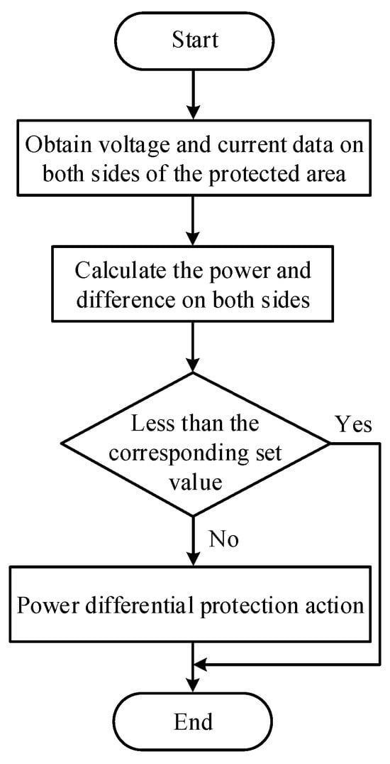
Figure 4.
Power differential protection flowchart.
Typically, voltage and current transformers are used to convert the high-voltage-side voltage and current into secondary signals according to the ratio, which are then utilized by protection devices. Within the system, the power on both sides and their differences are calculated and compared with the corresponding secondary set values to determine if the protection should be activated. In a fault event, the communication and control system is used to transmit protection information and implement fault isolation, involving communication protocols, data transmission reliability, and the operation of control equipment.
For AC systems, the three-phase voltage and current are directly measured to calculate power; for DC systems, a voltage divider and a DC current transformer are used to measure DC voltage and current, and DC power is calculated; for interconnection converter interfaces in AC/DC hybrid systems, measurement points are required on both the AC and DC sides of the interconnection converter.
Furthermore, high-frequency harmonics or transient noise can affect measurement accuracy, necessitating the addition of low-pass filters or digital filtering algorithms on the sensor side or in protective devices. To mitigate the risk of data loss, redundant communication design and data transmission mechanisms can enhance reliability. Ground asymmetry faults can cause zero-sequence component interference, requiring the use of sequence component separation algorithms to extract positive-sequence power.
4. Case Simulation and Analysis
In this section, a DC line, a transformer, and an interconnection converter are adopted as examples to explain the protection method.
4.1. Case Settings
In the case of isolated operation, the flexible AC/DC microgrid has limited system capacity and lacks support from the public power grid. This paper focuses on the relatively unstable isolated state. Using the MATLAB R2023a/Simulink platform, a simulation model of the flexible AC/DC microgrid topology shown in Figure 5 is established, as illustrated in Figure 6. The model simulates the power difference characteristics on both sides of the DC line, transformer, and interconnection converter to verify the correctness and practicality of the proposed differential protection method.
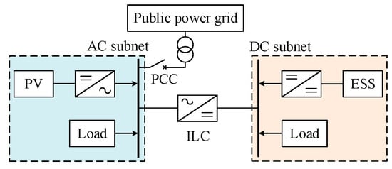
Figure 5.
Flexible AC/DC distribution microgrid simulation topology.
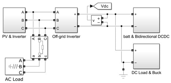
Figure 6.
Flexible AC/DC distribution microgrid simulation model.
In this example, the AC microgrid includes a photovoltaic system and AC loads. The photovoltaic cells are connected in parallel to the 380 V AC bus through a three-phase inverter, while the AC loads are directly connected in parallel to the AC bus. The DC microgrid includes an energy storage system and DC loads. The battery is connected in parallel to the DC bus through a bidirectional DC/DC converter, and the DC load is connected in parallel to the DC bus through a Buck circuit. The AC bus and the DC bus are interconnected via an interconnection converter.
The simulation parameters and control strategies of flexible AC/DC distribution microgrid are shown in Table 1 and Table 2, respectively. The peak voltage of photovoltaic is 359 V and the peak current is 15A.

Table 1.
Simulation parameters of flexible AC/DC microgrid.
Table 2.
Flexible AC/DC microgrid control strategy.
According to the result, it is shown that the frequency of the flexible AC/DC microgrid remains at about 50 Hz during the process of grid connection and island operation.
The power direction of the interconnection converter is defined as flowing from the DC bus to the AC bus, meaning the inverter state is positive, and negative otherwise. When setting 1 s, the AC load is disconnected, as illustrated in Figure 7, Figure 8 and Figure 9. At this point, energy storage switches from discharge to charge, and the interconnection converter transitions from inverter to rectifier mode.
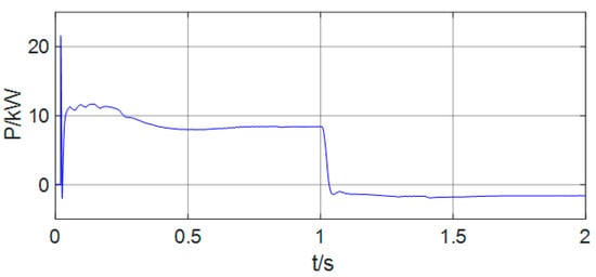
Figure 7.
Curves of battery power.
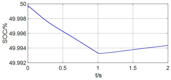
Figure 8.
Curves of battery SOC.
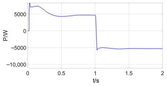
Figure 9.
Active power of interconnected converters.
It is shown that the energy storage system and the interconnection converter can be automatically switched in different working states, which proves the correctness of the model.
As for AC faults, a phase A ground fault is taken for example, positive sequence AC power is measured, and the fault time is set from 1 s to 1.4 s. The following sections simulate various operating conditions of DC lines, transformers, and interconnected converters to detail the protection method proposed in this paper. Then, both positive and negative represent direction, and the set values are all positive.
4.2. DC Line Power Differential Protection
The schematic diagram of instantaneous power of the DC line is shown in Figure 10, which simulates normal circumstances, out-of-zone fault, and in-zone fault, respectively.
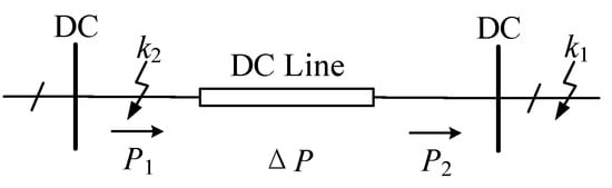
Figure 10.
Schematic diagram of instantaneous power of DC line.
4.2.1. Normal Circumstances
As shown in Figure 11, due to power loss and other reasons in the DC line, under normal circumstances, after a transient process of 0.5 s, the power difference on both sides of the DC line tends to stabilize at a value of 109 W.
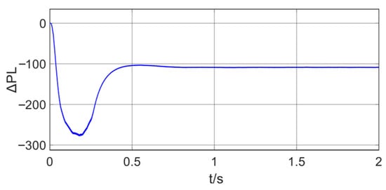
Figure 11.
Power difference on both sides of the DC line (normal).
4.2.2. Out-Zone Faults
As shown in Figure 12, when the fault occurs outside the zone, that is, the fault occurs at point k1, the power difference on both sides of the DC line is the same as normal.
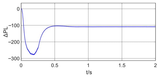
Figure 12.
Power difference on both sides of the DC line (out-of-zone fault).
4.2.3. In-Zone Faults
As shown in Figure 13, when the fault occurs in the zone, that is, the fault occurs at point k2, the power difference on both sides of the DC line increases sharply to 4731 W; 1.4 s at the initial moment of the fault, that is, at 1 s. After the fault is removed, the system gradually recovers to a stable state.
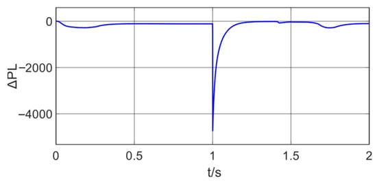
Figure 13.
Power difference on both sides of the DC line (in-zone fault).
As shown in Figure 11, Figure 12 and Figure 13, the power difference on both sides of the DC line is negative by 109 W under normal conditions and during external faults. During internal faults, the instantaneous peak power difference on both sides is negative by 4731 W. If only the protection of the DC line is considered, given that the power differences on both sides are negative, it is unnecessary to install a power direction element. Instead, setting the threshold value ΔPset between 109 W and 4731 W is sufficient.
4.3. Transformer Power Differential Protection
The schematic diagram of transformer instantaneous power is shown in Figure 14, which simulates normal circumstances, out-of-zone fault, and in-zone faults, respectively.
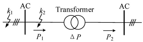
Figure 14.
Schematic diagram of transformer instantaneous power.
4.3.1. Normal Circumstances
As shown in Figure 15, the maximum power difference between the two sides of the transformer reaches 29 W; due to the internal power loss and other reasons, under normal circumstances, after 1 s, the power difference between the two sides of the transformer tends to stabilize at 21 W.
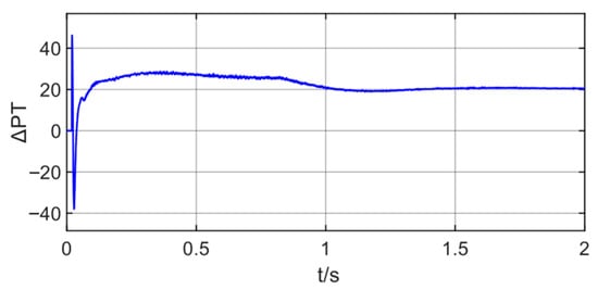
Figure 15.
Power difference on both sides of the transformer (normal).
4.3.2. Out-of-Zone Faults
As shown in Figure 16, when the fault occurs outside the area, that is, the fault occurs at point k1, the power difference on both sides of the transformer is the same as the normal situation.
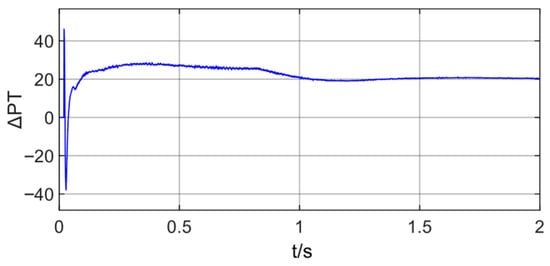
Figure 16.
Power difference on both sides of the transformer (out-of-zone fault).
4.3.3. In-Zone Faults
As shown in Figure 17, when the fault occurs in the zone, that is, the fault occurs at point k2, the power difference between the two sides of the transformer increases sharply during the fault process, and the spike peak reaches 7841 W; 1.4 s. After the fault is removed, the system gradually recovers to a stable state.
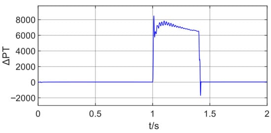
Figure 17.
Power difference on both sides of the transformer (in-zone fault).
As shown in all Figure 16, Figure 17 and Figure 18, the maximum power difference on both terminals of the transformer is positive at 29 W under normal and out-of-zone fault conditions. In the case of a zone fault, the maximum power difference on both sides is positive at 7841 W. For transformer protection, given that the power differences on both sides are positive, it is unnecessary to install a power direction element. Instead, setting the threshold ΔPset between 29 W and 7841 W is sufficient.
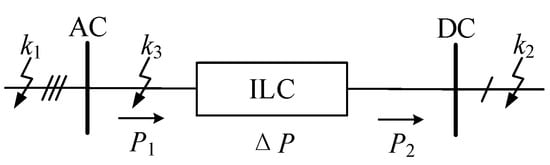
Figure 18.
Schematic diagram of instantaneous power of interconnected converters.
4.4. Power Differential Protection of Interconnected Converters
The interconnection converter serves as the core interface device linking the AC and DC subnets. Its protection failure directly threatens the AC/DC energy interaction channel, affecting the system’s topological flexibility and multi-source coordination capabilities. The power diagram is illustrated in Figure 18, simulating normal conditions, out-of-zone (AC-side and DC-side) faults, and in-zone faults.
4.4.1. In-Zone Faults
As shown in Figure 19, due to the power loss inside the interconnection converter and other reasons, under normal circumstances, after a transient process of 0.5 s, the power difference between the two sides of the interconnection converter tends to stabilize at 62 W.
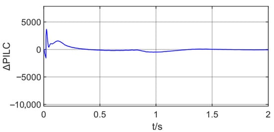
Figure 19.
Power difference between the two sides of the interconnection converter (normal).
4.4.2. Out-of-Zone Communication-Side Fault
As shown in Figure 20, when the AC side outside the zone fails, that is, the k1 point fails, the power difference between the two sides of the interconnection converter increases sharply during the fault process, and the spike peak reaches 4576 W; 1.4 s. After the fault is removed, the system gradually recovers to a stable state.
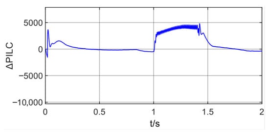
Figure 20.
Power difference between the two sides of the interconnection converter (out-of-zone/AC-side fault).
4.4.3. DC-Side Fault Outside the Zone
As shown in Figure 21, when the DC side outside the zone fails, that is, the k2 point fails, the power difference between the two sides of the interconnection converter increases sharply to 4653 W; 1.4 s at the initial moment of the failure, that is, 1 s. After the fault is removed, the system gradually recovers to a stable state.
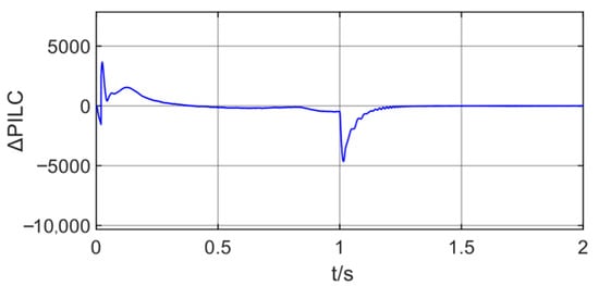
Figure 21.
Power difference between the two sides of the interconnection converter (out-of-zone/DC-side fault).
4.4.4. DC-Side Fault Outside the Zone
As shown in Figure 22, when the fault occurs in the zone, that is, the fault occurs at point k3, the power difference between the two sides of the interconnection converter increases sharply during the fault process, and the spike peak reaches 8515 W; 1.4 s. After the fault is removed, the system gradually recovers to a stable state.
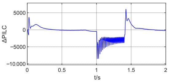
Figure 22.
Power difference between the two sides of the interconnection converter (in-zone fault).
As shown in Figure 19, Figure 20, Figure 21 and Figure 22, under normal conditions, the power difference between the two sides of the interconnected converter is negative, at 62 W. In the case of an external AC-side fault, the maximum power difference is positive, at 4576 W. For an external DC-side fault, the maximum power difference is negative, at 4653 W. During internal faults, the maximum power difference is also negative, at 8515 W. For protection of the interconnected converter, a positive power difference indicates an external AC-side fault, while a negative power difference indicates a normal condition, an external DC-side fault, or an internal fault. It is not possible to distinguish internal faults based on the power direction alone. However, considering that the absolute maximum power difference between the two sides is 4653 W for both normal and external (AC-side/DC-side) faults, which is less than the 8515 W for internal faults, it is unnecessary to install a power direction element. Instead, setting the threshold ΔPset, with ILC between 4653 W and 8515 W, is sufficient.
All three equipment, DC line, transformer and interconnection converter, have been analyzed before, and the conclusions for other equipment are similar.
5. Conclusions
This article proposes a universal differential protection method based on active power difference to address the protection adaptation challenges of flexible AC microgrids. The core principle is to capture the power balance characteristics on both sides of the protected component during internal faults. Simulation analysis confirms that this method can effectively distinguish the normal operation of components, out-of-zone faults, and in-zone fault states, demonstrating excellent universality and reliability. It provides a concise and effective protection approach for modern distribution networks that include AC/DC converters and high proportion power electronic equipment. However, this study still has certain limitations. For example, simulation verification mainly focuses on typical short-circuit faults under islanded operating conditions, and its adaptability to more complex working conditions such as grid connected operation and high impedance faults needs further testing. Meanwhile, the protection performance depends to some extent on the accuracy of data measurement and the real-time communication. Subsequent research can focus on several key directions: firstly, to explore in depth the performance optimization strategies of this method in dealing with complex scenarios such as high impedance faults; second, to study how to improve the robustness of protection under non-ideal conditions such as communication limitations.
Author Contributions
Conceptualization, M.C.; methodology, Y.X.; software, C.W.; validation, C.W. and X.Z.; writing—original draft preparation, D.Z. and Q.C.; writing—review and editing, Y.X. and Q.C.; project administration, D.Z. All authors have read and agreed to the published version of the manuscript.
Funding
This article is supported by the Key Project of National Natural Science Foundation of China (51837004).
Data Availability Statement
Data are contained within this article.
Conflicts of Interest
Authors Yigong Xie, Chen Wu, Min Cheng and Dan Zhang were employed by the company Yunnan Power Grid Electric Power Dispatching and Control Center. Author Xiao Zhang was employed by the company Nanjing Nari-Relays Engineering Technology Company. The remaining authors declare that the research was conducted in the absence of any commercial or financial relationships that could be construed as a potential conflict of interest.
References
- Ganjian-Aboukheili, M.; Shahabi, M.; Shafiee, Q.; Guerrero, J.M. Seamless transition of microgrids operation from grid-connected to islanded mode. IEEE Trans. Smart Grid 2020, 11, 2106–2114. [Google Scholar] [CrossRef]
- Li, X.; Gao, J.; You, S.; Zheng, Y.; Zhang, Y.; Du, Q.; Xie, M.; Qin, Y. Optimal design and techno economic analysis of renewable-based multi-carrier energy systems for industries: A case study of a food factory in China. Energy 2022, 244, 123174. [Google Scholar] [CrossRef]
- Yuan, M.; Zhou, Z.; Cai, X.; Sun, C.; Gu, W. Service composition model and method in cloud manufacturing. Robot. Comput.-Integr. Manuf. 2020, 61, 101840. [Google Scholar] [CrossRef]
- Sahoo, S.K.; Sinha, A.K.; Kishore, N.K. Control techniques in AC, DC, and hybrid AC-DC microgrid: A review. IEEE J. Emerg. Sel. Top. Power Electron. 2018, 6, 738–759. [Google Scholar] [CrossRef]
- Sun, K.; Wang, X.; Li, Y.W.; Nejabatkhah, F.; Mei, Y.; Lu, X. Parallel operation of bidirectional interfacing converters in a hybrid AC-DC microgrid under unbalanced grid voltage conditions. IEEE Trans. Power Electron. 2017, 32, 1872–1884. [Google Scholar] [CrossRef]
- Blackburn, L.J.; Domin, J.T. Protective Relaying. In Taylor and Francis; CRC Press: Boca Raton, FL, USA, 2015. [Google Scholar]
- Zhang, L.; Ruan, X.B.; Ren, X.Y. Second-harmonic current reduction and dynamic performance improvement in the two-stage inverters: An output impedance perspective. IEEE Trans. Ind. Electron. 2014, 62, 394–404. [Google Scholar] [CrossRef]
- Loh, P.C.; Li, D.; Chai, Y.K.; Blaabjerg, F. Autonomous control of interlinking converter with energy storage in hybrid AC/DC microgrid. IEEE Trans. Ind. Appl. 2013, 49, 1374–1382. [Google Scholar] [CrossRef]
- Shen, X.; Tan, D.; Shuai, Z.; Luo, A. Control Techniques for Bidirectional Interlinking Converters in Hybrid Microgrids: Leveraging the advantages of both ac and dc. IEEE Power Electron. Mag. 2019, 6, 39–47. [Google Scholar] [CrossRef]
- El-Naily, N.; Saad, S.M.; Mohamed, F.A. Novel approach for optimum coordination of overcurrent relays to enhance microgrid earth fault protection scheme. Sustain. Cities Soc. 2020, 54, 102006. [Google Scholar] [CrossRef]
- Naik, J.; Dhar, S.; Dash, P.K. Effective fault diagnosis and distance calculation for photovoltaic-based DC microgrid using adaptive EWT and kernel random vector functional link network. IET Gener. Transm. Distrib. 2020, 14, 690–703. [Google Scholar] [CrossRef]
- Wang, L.; Li, M.; Deng, X. Research on modelling and simulation of converters for electromagnetic transient simulation in photovoltaic power generation system. IET Gener. Transm. Distrib. 2019, 13, 4558–4565. [Google Scholar] [CrossRef]
- Yang, H.; Meng, C.; Wang, C. Data-driven feature extraction for analog circuit fault diagnosis using 1-D convolutional neural network. IEEE Access 2020, 8, 18305–18315. [Google Scholar] [CrossRef]
- Jiang, Y.; Xia, L.; Zhang, J. A Fault Feature Extraction Method for DC-DC Converters Based on Automatic Hyperparameter-Optimized 1-D Convolution and Long Short-Term Memory Neural Networks. IEEE J. Emerg. Sel. Top. Power Electron. 2021, 10, 4703–4714. [Google Scholar] [CrossRef]
- Jung, J.J.; Cui, S.; Lee, J.H.; Sul, S.K. A new topology of multilevel VSC converter for a hybrid HVDC transmission system. IEEE Trans. Power Electron. 2017, 32, 4199–4209. [Google Scholar] [CrossRef]
- Qi, M. Analysis of Fault Characteristics and Protection Technology of Low-Voltage DC Microgrid; Chongqing University: Chongqing, China, 2018. [Google Scholar]
- Liu, W.; Xiong, X.; Yang, H.; Feng, K.; Liu, F. Combined optimization of SSCB snubber and freewheeling path for surgeless and quick bus fault interruption in low-voltage DC microgrid. In Proceedings of the 2016 IEEE Energy Conversion Congress and Exposition (ECCE), Milwaukee, WI, USA, 18–22 September 2016; IEEE: New York, NY, USA, 2017; pp. 1–5. [Google Scholar]
- Ustun, T.S.; Ozansoy, C.; Zayegh, A. A microgrid protection system with central protection unit and extensive communication. In Proceedings of the 2011 10th International Conference on Environment and Electrical Engineering, Rome, Italy, 8–11 May 2011; pp. 1–4. [Google Scholar]
- Shamsoddini, M.; Vahidi, B.; Razani, R.; Mohamed, Y.A.-R.I. A novel protection scheme for low voltage DC microgrid using inductance estimation. Int. J. Electr. Power Energy Syst. 2020, 120, 105992. [Google Scholar] [CrossRef]
- Ghadiri, S.M.E.; Mazlumi, K. Adaptive protection scheme for microgrids based on SOM clustering technique. Appl. Soft Comput. J. 2020, 88, 106062. [Google Scholar] [CrossRef]
- Ge, J.; Shuai, Z.; Zhao, H.; Shen, Z.J. Generalized power and current control for three-phase four-wire converter under unbalanced grid conditions. In Proceedings of the IECON 2019—45th Annual Conference of the IEEE Industrial Electronics Society, Lisbon, Portugal, 14–17 October 2019; pp. 3900–3905. [Google Scholar]
Disclaimer/Publisher’s Note: The statements, opinions and data contained in all publications are solely those of the individual author(s) and contributor(s) and not of MDPI and/or the editor(s). MDPI and/or the editor(s) disclaim responsibility for any injury to people or property resulting from any ideas, methods, instructions or products referred to in the content. |
© 2026 by the authors. Licensee MDPI, Basel, Switzerland. This article is an open access article distributed under the terms and conditions of the Creative Commons Attribution (CC BY) license.