Abstract
Floating offshore wind turbines (FOWTs) are essential for meeting global renewable energy goals, yet their viability depends strongly on platform motion in harsh marine environments and the resulting influence on structural loading and the levelized cost of energy. This study examines the dynamic response of a 15 MW semi-submersible FOWT based on the IEA-15-240-RWT developed by NREL. The baseline UMaine VolturnUS-S platform is evaluated alongside two newly proposed variants, KSNU-1 15 MW and KSNU-2 15 MW, each equipped with distinct heave-plate configurations designed to enhance hydrodynamic damping while maintaining equal surface area for fair comparison. Hydrodynamic coefficients are obtained through potential-flow analysis using Ansys Aqwa, and fully coupled aero-hydro-servo-elastic simulations are conducted with OpenFAST. The performance of all platforms is assessed under two design load cases (DLCs): the fatigue limit state (FLS) and the ultimate limit state (ULS). The results show that both KSNU platforms achieve slight reductions in surge, sway, and heave motions, with KSNU-2 providing the most consistent improvement in vertical and horizontal stability. Rotational responses increase modestly but remain within acceptable limits. Overall, the KSNU-2 design demonstrates improved motion control without compromising energy output, offering a promising configuration for large-scale floating wind applications.
1. Introduction
With the growing global demand for clean and sustainable energy, offshore wind power has become a vital element in the global energy transition. In particular, deep-sea offshore areas offer stronger and more stable wind resources than onshore sites. However, conventional fixed-bottom wind turbines face considerable challenges in deep-water deployment due to installation and maintenance constraints. Therefore, ultra-large capacity floating offshore wind turbines (FOWTs) have gained considerable attention for their suitability in deep-sea environments and are viewed as a highly promising solution for the future expansion of offshore wind power.
The development of ultra-large capacity turbines has accelerated the deployment of FOWTs by improving power generation efficiency and reducing the levelized cost of energy (LCOE). These high-capacity systems increase energy output per unit while enabling more optimized wind farm layouts that enhance overall energy utilization. However, as turbine size continues to grow, new challenges emerge in maintaining dynamic stability and structural safety, particularly under complex marine conditions where wind, wave, and current interactions are highly coupled.
Despite these technological advancements, several barriers still hinder the large-scale commercialization of FOWT technology. These challenges extend across the floating offshore wind farm (FOWF) lifecycle, including installation, operation, maintenance, and decommissioning. Installation cost and complexity remain among the most significant issues, considering the global ambition to reach 270 GW of FOWF capacity by 2050, as illustrated in Figure 1 [1]. Meeting this target would require deploying more than seven hundred 15 MW turbines each year. To achieve such a vision, effective site planning, comprehensive assessment of both physical and human resources, and sustained research and development aimed at improving installation efficiency are essential.
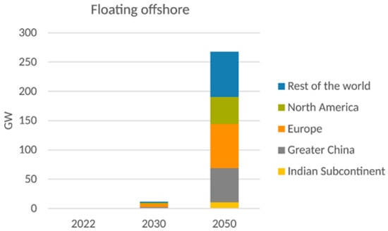
Figure 1.
World installed and expected FOW capacity by region [1].
Addressing these challenges has become a central focus of ongoing research, with many studies dedicated to improving the design and performance of floating offshore wind systems. Recent research efforts have concentrated on platform design and hydrodynamic response to enhance the overall performance and reliability of FOWTs. Liu et al. [2] performed full-scale CFD simulations to predict turbine performance, demonstrating the importance of time discretization strategies in balancing numerical accuracy and computational efficiency. Rinker et al. [3] emphasized the necessity of capturing coupled aerodynamic, hydrodynamic, and structural interactions in high-fidelity simulations. Xu et al. [4] investigated the effects of wind shear, turbulence intensity, and coherence using coupled aero-hydro-servo-elastic simulations, revealing that turbulence intensity has the most significant influence on platform motion and structural loading. de Oliveira et al. [5] utilized AQWA and OpenFAST to analyze second-order hydrodynamic loads on a 15 MW turbine, while Meng et al. [6] compared the aeroelastic responses of the IEA Wind 15 MW reference turbine between OpenFAST and HAWC2, noting consistency in aerodynamic-dominant loads and discrepancies in asymmetric responses.
Building upon these simulation-based investigations, further studies have examined wake interaction and scaling effects to better represent full-scale turbine behavior. Bazher et al. [7] employed STAR-CCM+ to combine CFD simulations with experimental data, validating the influence of scaling on wake characteristics despite the rigid-body assumption. Haider et al. [8] reviewed the application of CFD in FOWT design and performance evaluation, emphasizing the importance of coupled aero-hydro-elastic modeling, particularly for large-diameter rotors. Papi and Bianchini [9] compared the performance of 5 MW and 15 MW turbines, finding that larger platforms can improve stability but may also amplify certain extreme loads as a result of platform motion.
In addition to aerodynamic and wake interaction studies, the mooring system has received significant attention for its influence on overall FOWT dynamics. Mei and Xiong [10] examined how mooring parameters affect platform motion and proposed cost-effective optimization strategies. Liang et al. [11] developed an OpenFOAM-based tool for simulating fluid–structure interaction (FSI) in FOWTs, providing three-dimensional quantitative data for aerodynamic, hydrodynamic, and mooring feedback effects. Chen et al. [12] designed a mooring system suitable for the South China Sea by coupling the IEA 15 MW turbine with the UMaine VolturnUS-S platform and conducted hydrodynamic and time-domain mooring tension analyses using Ansys Aqwa. Eliassen and Bachynski [13] assessed platform motion and mooring fatigue under varying environmental conditions. Lu [14] applied CFD simulations with dynamic overset mesh in STAR-CCM+ to validate the hydrodynamic and aerodynamic responses of a semi-submersible FOWT system.
Beyond mooring considerations, structural optimization of the support platform has become a focal point in improving FOWT motion behavior and stability. One of the key challenges in FOWT development is the mitigation of platform dynamic responses and maintaining operational stability under harsh marine conditions. Optimizing platform geometry has proven to be an effective approach to enhance overall performance. In particular, heave plates have shown strong capability in suppressing platform motion by increasing hydrodynamic damping. Pan et al. [15] introduced a semi-submersible foundation featuring a specially designed heave plate that significantly improved heave-motion suppression and platform stability. Medina-Manuel et al. [16] conducted forced-oscillation and free-decay tests to determine hydrodynamic coefficients of columns equipped with solid heave plates, providing valuable reference data for full-scale simulations. Mello et al. [17] examined the effects of large-skirted heave plates and validated viscous damping predictions through experimental comparisons, offering insights for future hull optimization.
Following extensive research on heave plate applications, subsequent studies have explored variations in damping structures to further improve motion performance. Wang et al. [18] evaluated the performance of inner and outer buoyancy plates on a 10 MW OO-Star platform, while Seo et al. [19] designed two damping-plate-equipped platforms based on the 5 MW OC5 configuration. Their findings confirmed that motion suppression was enhanced by vortex-induced viscous damping effects. However, despite considerable advances in platform design and motion control, a comprehensive understanding of how different heave plate configurations influence the hydrodynamic performance and stability of ultra-large FOWTs under varying sea states remains limited.
To address this gap, the present study focuses on evaluating the dynamic response of a 15 MW semi-submersible FOWT based on the IEA 15 MW reference turbine (IEA-15-240-RWT). The baseline UMaine VolturnUS-S platform [20] is compared with two newly proposed semi-submersible variants, KSNU 15 MW-1 and KSNU 15 MW-2, each incorporating distinct heave-plate configurations aimed at enhancing motion damping and hydrodynamic stability. The primary objective is to identify suitable heave-plate geometries and to compare their influence on the global motion and power performance of the semi-submersible configurations. Potential-flow hydrodynamics are first computed using Ansys AQWA and then imported into OpenFAST, where fully coupled aero hydro servo elastic simulations are carried out using a numerical model that is based on linear potential flow complemented by additional viscous damping in the HydroDyn module. In this study, collinear wind and wave conditions are assumed to create a clear and controlled loading environment, providing a consistent basis for comparing the different heave plate configurations and establishing a reference case that can be extended in future work to more complex metocean conditions. Within this framework, two design load cases (DLCs), namely the fatigue limit state (FLS) and ultimate limit state (ULS), are considered to evaluate structural dynamics and quantify the influence of heave-plate geometry on the overall dynamic behavior. The results are benchmarked against the baseline platform to assess improvements in motion performance, hydrodynamic response, and operational stability, offering practical guidance for future FOWT platform optimization. In addition, the adopted numerical framework is intended as a less expensive computational method that still covers all key aspects for the analysis, providing a practical way to identify appropriate shapes of structural appendages such as heave plates.
2. Properties of the 15 MW Semi-Submersible FOWT Platform
2.1. Structural and Mooring Properties of the Reference Platform
The UMaine VolturnUS-S semi-submersible platform serves as the reference model in this study. This turbine represents a generic steel adaptation of the patented concrete floating technology developed by the University of Maine (UMaine) in collaboration with the U.S. Department of Energy [20]. As shown in Figure 2, the semi-submersible platform consists of a central main column supporting the tower and three offset columns connected to the main column by pontoons and cross-braces. Table 1 and Table 2 summarize the principal characteristics of the prototype wind turbine, while more detailed specifications can be found in the NREL report [20]. The following section describes the numerical modeling framework and simulation setup employed to evaluate the hydrodynamic and dynamic performance of the proposed platforms.
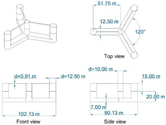
Figure 2.
Detailed dimensions of the semi-submersible foundation [21].

Table 1.
UMaine VolturnUS-S reference platform properties [20].
Table 2.
Mooring system properties [20].
The mooring system design for the UMaine VolturnUS-S platform adopts a catenary configuration consisting of three chain lines, each 850 m in length. Each mooring line is attached to one of the three offset columns of the platform at a depth of 14 m below the still water line (SWL). As illustrated in Figure 3, the lines extend radially to anchors positioned in the roll plane at 120° intervals, located at a water depth of 200 m and a radial distance of 837.6 m from the tower centerline. The mooring lines are made of studless R3-grade chains with a nominal diameter of 185 mm. Drag and added-mass coefficients for the mooring system, summarized in Table 2, were selected according to DNVGL-RP-C205 (Environmental Conditions and Environmental Loads) [22] and DNVGL-OS-E301 (Position Mooring) [23].
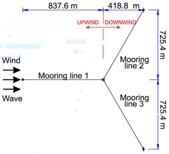
Figure 3.
Plan view showing the details of mooring configuration [24].
2.2. Heave Plate Concept Design
In order to see how heave plates affect the dynamic behavior of a semi-submersible floating wind turbine, two designs named KSNU-1 15 MW and KSNU-2 15 MW are proposed. Both models share the same thickness and total surface area to ensure a fair comparison. The thickness follows the 0.5 m recommendation suggested by Wang et al. [18], and the width is determined using the proportion proposed by Seo et al. [19]. The shape of the lower damping plate varies according to the geometry of the lower part of the platform and is attached to the column base, following the design concept of Park et al. [25]. The arrangement follows Seo et al. [19] by applying the diameter ratio of the column and the damping plate at 1:1.74, and this ratio is adopted consistently in the present design. Inspired by the platform configuration investigated by Mello et al. [17], two heave-plate layouts are considered: one with a conventional solid plate and another in which the upper and lower surfaces of the auxiliary structure are removed to enhance vortex-induced viscous effects. Based on this ratio, the plate width of KSNU-1 15 MW is first defined, from which its total surface area of about 1672 m2 is calculated. This area then serves as the reference to keeping KSNU-2 15 MW equal in total surface coverage. The dimensions of each triangular plate in KSNU-2 15 MW are later obtained by back-calculating from that value.
The configurations of KSNU-1 15 MW and KSNU-2 15 MW draw inspiration from the SHLB platform introduced by Meng et al. [6]. The heave plate is a single, flat, rounded-triangular plate that links the three circular column bases, forming a smooth three-lobed shape around the platform. Their research showed that the SHLB concept provided strong damping of heave motion. Building on this idea, the modified KSNU platforms in this study apply the same design logic to the UMaine VolturnUS-S reference model.
The KSNU-1 15 MW platform, shown in Figure 4, features a continuous heave plate installed around the base of the floating wind turbine structure. The plate extends uniformly along the entire perimeter of the platform with a constant width of 4.625 m. In contrast, the KSNU-2 15 MW configuration, shown in Figure 5, incorporates heave plates within the triangular regions formed between each pair of offset columns and the central main column. Each triangular plate is an isosceles shape with an apex angle of 120° and equal side lengths of 35.88 m.
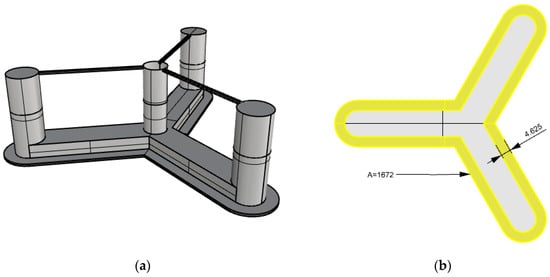
Figure 4.
KSNU-1 15 MW platform: (a) Three-dimensional model; (b) Heave plate geometry.
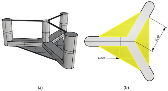
Figure 5.
KSNU-2 15 MW platform: (a) Three-dimensional model; (b) Heave plate geometry.
The hydrodynamic effects of heave plates are central to their performance in mitigating the vertical dynamic response of floating platforms. In the KSNU-1 15 MW design, the continuous flat-plate layout provides a uniform distribution of hydrodynamic forces along the entire perimeter of the platform base. This configuration is expected to enhance the added-mass effect and viscous damping by increasing the effective surface area exposed to fluid motion, thereby improving energy dissipation from wave-induced motions. The continuous geometry also promotes consistent flow separation and reattachment patterns, contributing to more stable vertical damping characteristics.
In contrast, the KSNU-2 15 MW design, characterized by its triangular plate geometry, introduces distinct hydrodynamic behavior due to its localized placement between the offset columns. The triangular plates, arranged at 120-degree intervals, utilize the directional flow patterns between the pontoons to induce additional vortex shedding and complex wake interactions. This configuration is anticipated to provide greater damping in specific loading directions, particularly under oblique wave conditions, while also improving lateral stability. The concentration of hydrodynamic forces at discrete locations may result in variations in added-mass and damping coefficients compared with the KSNU-1 15 MW configuration, offering a balanced combination of stability, dynamic response control, and structural efficiency.
By comparing these two configurations, this study seeks to quantify the trade-offs between continuous and segmented heave-plate designs, providing insight into their respective advantages for optimizing platform stability and minimizing motion amplitudes in dynamic offshore environments.
3. Numerical Simulation Framework
Numerous aero-hydro-elastic simulation programs are widely used for the numerical analysis of floating offshore wind turbines (FOWTs). Prominent examples include Bladed, HAWC2, OpenFAST, and OrcaFlex. These tools incorporate modules that enable analysis across several key domains: aerodynamic performance (aero), hydrodynamic interactions with waves and currents (hydro), control systems (servo), and structural dynamics (elastic) [17].
In this study, the dynamic response characteristics of the FOWT are modeled using OpenFAST, an open-source wind turbine simulation tool developed by the National Renewable Energy Laboratory (NREL) [26]. OpenFAST originated from FAST v8 [27], which was transitioned into an open-source framework by NREL researchers in 2017 to better support collaboration among research institutions, industry, and academia. The program provides a well-structured software framework and transparent documentation, enabling reliable simulation of coupled aerodynamic, hydrodynamic, control, and structural interactions.
The present study employs OpenFAST version 4.1.2. The software is organized into a modular framework in which each module represents a specific physical process. AeroDyn handles aerodynamic forces, HydroDyn models hydrodynamic loading, ServoDyn simulates the control system behavior, and ElastoDyn captures structural dynamics. This framework allows the numerical coupling of aerodynamic, hydrodynamic, and structural responses under prescribed control strategies, enabling accurate simulation of the turbine’s overall motion and load characteristics.
3.1. Hydrodynamic Frequency Domain Analysis Using Ansys Aqwa
To accurately represent the hydrodynamic characteristics of the semi-submersible platform in OpenFAST, the potential flow hydrodynamic properties of the platform geometry were computed using the commercial boundary-element-method-based solver Ansys Aqwa [28]. The resulting data, including hydrostatic stiffness and frequency-dependent hydrodynamic coefficients such as added mass, radiation damping, and wave excitation forces, were used as inputs for the hydrodynamic module (HydroDyn) in OpenFAST. The analysis was based on linear potential flow theory, assuming inviscid, irrotational, and incompressible flow conditions.
As shown in Equation (1), the motion of a floating body is governed by equations of motion the inertial terms (M + A): structural mass (M) and frequency-dependent added-mass (A(ω)), radiation damping (Brad(ω)), viscous damping (Bvisc), hydrostatic and mooring restoring stiffnesses (Chydro + Cmoor), and wave-induced external force (Fext). In this process, the hydrodynamic load is derived through potential flow theory, and Fext is defined as the sum of the diffraction force and the Froude–Krylov force.
A total of 60 wave frequencies were analyzed, starting from 0.05 rad/s and extending to 3.0 rad/s, divided into 59 uniform intervals of 0.05 rad/s. The wetted surface of the platform was discretized into hydrodynamic panels, enabling evaluation of the frequency response across all six degrees of freedom (6DOF). The resulting data were then exported in a format compatible with HydroDyn’s potential-flow configuration (PotMod = 1), allowing direct coupling within the OpenFAST framework.
3.1.1. Grid Distribution Setup for the Potential-Flow Model
A grid convergence study was conducted to verify numerical accuracy and assess the sensitivity of the hydrodynamic coefficients to mesh refinement. Several mesh densities are tested by varying the number of panels along the platform’s hull and pontoon surfaces. The convergence criterion is based on the response amplitude operators (RAOs) that are critical for semi-submersible (which is heave, roll, and pitch). The error percentage of the heave, roll, and pitch RAO at the wave frequency of ≈0.85 rad/s are compared within all mesh configurations and shown in Figure 6 and Table 3. As a result, a medium-fine mesh is selected, with the error closest to the fine mesh, ensuring fidelity without excessive computational cost. The medium-fine mesh configuration is used in all analysis of potential flow models.
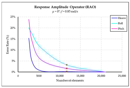
Figure 6.
Variation in error rate of heave, roll, and pitch RAOs with respect to the number of elements.
Table 3.
Grid convergence study results.
3.1.2. Validation of the Potential-Flow Model
Validation of the potential-flow model is conducted by comparing the Ansys Aqwa-generated results with reference GitHub datasets for the UMaine VolturnUS-S. The hydrostatic stiffness and frequency-dependent added mass and damping coefficients are verified to ensure physical consistency. The comparison of the Ansys Aqwa generated re-sult and the WAMIT are shown in Table 4, Figure 7 and Figure 8. The validated model provides confidence in the use of Aqwa-generated hydrodynamic data within OpenFAST simula-tions for realistic dynamic response prediction.
Table 4.
Hydrostatic stiffness evaluated by Ansys Aqwa with error rate.
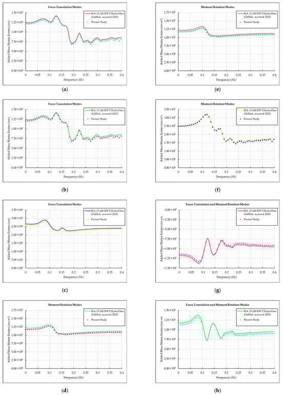
Figure 7.
Comparison of the added mass in frequency between the technical report and present study; (a) Surge; (b) Sway; (c) Heave; (d) Roll; (e) Pitch; (f) Yaw; (g) Surge-Pitch; (h) Sway-Roll.
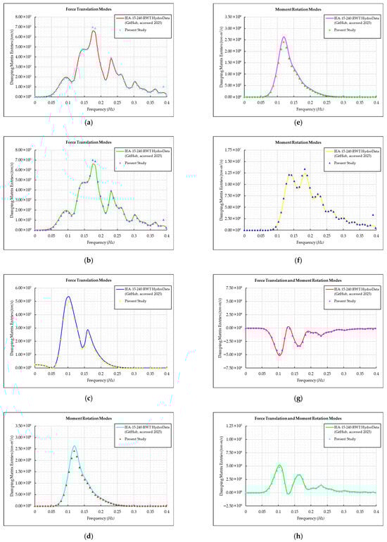
Figure 8.
Comparison of the damping coefficient in frequency between the technical report and present study; (a) Surge; (b) Sway; (c) Heave; (d) Roll; (e) Pitch; (f) Yaw; (g) Surge-Pitch; (h) Sway-Roll.
3.1.3. Representation of Viscous Damping in the Hydrodynamic Model
The HydroDyn module of OpenFAST represents viscous contributions through linear and quadratic Morison type drag terms that act on the submerged members based on the instantaneous relative motion between the structure and the surrounding water [29]. These drag forces provide an effective engineering description of flow separation, form drag, and energy dissipation at larger motion amplitudes. At the system level, these Morison type contributions can be interpreted as an additional viscous damping matrix (Bvisc) that supplements the radiation damping Brad(ω) and increases the overall energy dissipation in surge, sway, heave, roll, pitch, and yaw [30].
In this study, the same modelling approach is adopted, and viscous effects are represented through this additional damping matrix, and the Morison type drag terms implemented in HydroDyn. This combined strategy, in which potential flow hydrodynamics are augmented by additional viscous damping and quadratic drag, is consistent with the modelling approach used for the UMaine VolturnUS S reference semi-submersible in OpenFAST, where potential flow loads are complemented by an additional viscous damping contribution that is calibrated for the platform geometry [20].
3.2. Set-Up for Aero-Hydro-Servo-Elastic Coupled Simulation Using OpenFAST
Aero-hydro-servo-elastic simulation tools such as OpenFAST are widely used for evaluating the dynamic performance of floating offshore wind turbines (FOWTs) due to their modular structure and ability to integrate aerodynamic, hydrodynamic, control, and structural subsystems within a unified framework. OpenFAST is recognized as a mid-fidelity modeling tool capable of providing reliable predictions of turbine responses under a wide range of operating and environmental conditions [31]. This flexibility makes it particularly suitable for simulating DLCs defined by international certification standards.
In this study, a subset of IEC 61400-1 (2020) [32] design load cases was selected to evaluate the performance of the reference semi-submersible FOWT under representative normal and extreme operating scenarios. The simulations were conducted with co-aligned wind and wave directions (0° heading), following the DLC configurations as depicted in the NREL technical report by Allen et al. (2020) [20]. The environmental conditions adopted for the numerical analysis are representative of the U.S. East Coast, particularly the Gulf of Maine, as characterized by the metocean datasets of Stewart et al. (2015) [33] and Viselli et al. (2015) [34]. The specific parameters employed for each simulation case are summarized in Table 5.
Table 5.
DLC conditions and environmental parameters considered in the coupled simulations.
4. Result and Discussion
4.1. Dynamic Response (6 DOFs Motion) Result
The aero-hydro-servo-elastic coupled simulation results for the KSNU 1 15 MW and KSNU 2 15 MW platforms are compared with the UMaine VolturnUS S across all six DOFs. Surge, sway, heave, roll, pitch, and yaw responses are presented in Figure 9, Figure 10, Figure 11, Figure 12, Figure 13 and Figure 14. Figure 9a, Figure 10a, Figure 11a, Figure 12a, Figure 13a and Figure 14a show the time-domain responses under the normal condition (FLS), while Figure 9b, Figure 10b, Figure 11b, Figure 12b, Figure 13b and Figure 14b show the corresponding responses under the extreme condition (ULS). The comparisons of maximum magnitude, mean displacement, and standard deviation for each motion component are summarized in Figure 9c, Figure 10c, Figure 11c, Figure 12c, Figure 13c and Figure 14c, Figure 9d, Figure 10d, Figure 11d, Figure 12d, Figure 13d and Figure 14d, and Figure 9e, Figure 10e, Figure 11e, Figure 12e, Figure 13e and Figure 14e, respectively.
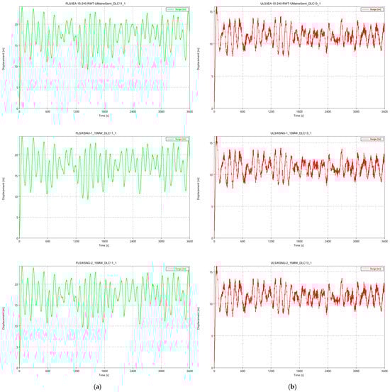
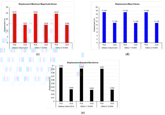
Figure 9.
OpenFAST coupled simulation results for surge motion; (a) Time history under FLS; (b) Time history under ULS, (c) Comparison of maximum displacement values; (d) Comparison of mean displacement values; (e) Comparison of displacement standard deviations for the UMaine VolturnUS-S, KSNU-1 15 MW, and KSNU-2 15 MW platforms.
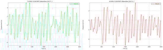
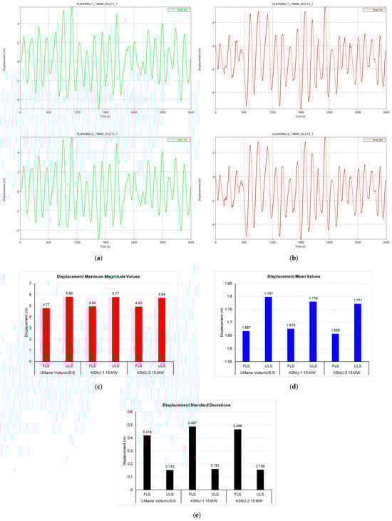
Figure 10.
OpenFAST coupled simulation results for sway motion; (a) Time history under FLS; (b) Time history under ULS, (c) Comparison of maximum displacement values; (d) Comparison of mean displacement values; (e) Comparison of displacement standard deviations for the UMaine VolturnUS-S, KSNU-1 15 MW, and KSNU-2 15 MW platforms.
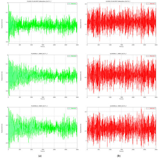
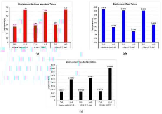
Figure 11.
OpenFAST coupled simulation results for heave motion; (a) Time history under FLS; (b) Time history under ULS, (c) Comparison of maximum displacement values; (d) Comparison of mean displacement values; (e) Comparison of displacement standard deviations for the UMaine VolturnUS-S, KSNU-1 15 MW, and KSNU-2 15 MW platforms.
Figure 12.
OpenFAST coupled simulation results for roll motion; (a) Time history under FLS; (b) Time history under ULS, (c) Comparison of maximum displacement values; (d) Comparison of mean displacement values; (e) Comparison of displacement standard deviations for the UMaine VolturnUS-S, KSNU-1 15 MW, and KSNU-2 15 MW platforms.
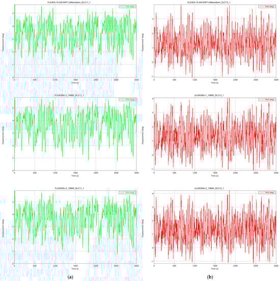
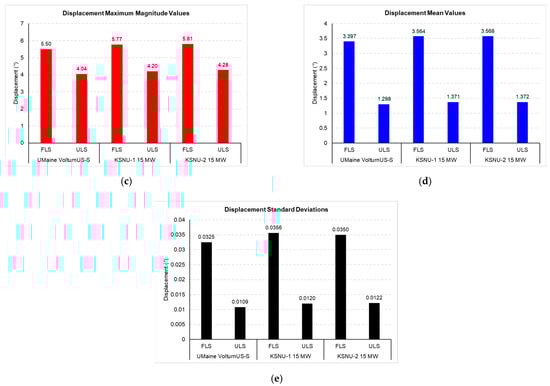
Figure 13.
OpenFAST coupled simulation results for pitch motion; (a) Time history under FLS; (b) Time history under ULS, (c) Comparison of maximum displacement values; (d) Comparison of mean displacement values; (e) Comparison of displacement standard deviations for the UMaine VolturnUS-S, KSNU-1 15 MW, and KSNU-2 15 MW platforms.
Figure 14.
OpenFAST coupled simulation results for yaw motion; (a) Time history under FLS; (b) Time history under ULS, (c) Comparison of maximum displacement values; (d) Comparison of mean displacement values; (e) Comparison of displacement standard deviations for the UMaine VolturnUS-S, KSNU-1 15 MW, and KSNU-2 15 MW platforms.
In terms of surge motion, the KSNU-2 platform demonstrates the strongest overall performance. It records the lowest surge amplitudes, with 17.11 m under FLS and 11.13 m under ULS, which corresponds to an improvement of about 0.3% relative to the UMaine VolturnUS-S baseline. This outcome reflects slightly higher stiffness and improved horizontal stability, largely due to the modified heave-plate configuration that increases hydrodynamic resistance to horizontal displacement. A similar trend appears in sway, where KSNU-2 exhibits 1.66 m under FLS and 1.77 m under ULS, roughly 0.6% lower than the UMaine VolturnUS-S platform. This indicates that the symmetrical plate geometry contributes to enhanced lateral damping and reduces cross-coupled motion effects.
For heave motion, all platforms show similar vertical responses of roughly 0.46 m under FLS. KSNU-2 achieves a slightly lower value, approximately 0.7% smaller than the UMaine VolturnUS-S platform, reflecting a modest improvement in added-mass damping. Under ULS conditions, heave motions decrease by about 10% for all platforms, demonstrating that the heave-plate structures effectively suppress vertical resonance and preserve adequate hydrostatic restoring capability in extreme seas. Taken together, the improvements in surge, sway, and heave remain within one percent, confirming that the KSNU designs enhance hydrodynamic damping while maintaining the overall stiffness characteristics of the baseline configuration.
For rotational motions, both KSNU-1 and KSNU-2 exhibit slightly larger roll and pitch amplitudes compared with the UMaine VolturnUS-S platform. Roll increases from 0.51 degrees to approximately 0.54–0.55 degrees, an increase of about 8%. Pitch motion rises by roughly 5%, from 3.40 degrees to 3.56–3.57 degrees under FLS. These modest increases indicate a slight reduction in rotational stiffness stemming from changes in buoyancy distribution and submerged geometry associated with the heave-plate modifications. Neverthless, the observed rotational responses remain within acceptable and controllable limits. Yaw motion remains nearly unchanged for all platforms, with values near 1.4 degrees under FLS and 3.0 degrees under ULS, demonstrating that directional control and yaw stability are not significantly influenced by the design changes.
4.2. Power Generation Result
The power production of the KSNU-1 15 MW and KSNU-2 15 MW platforms in comparison with the UMaine VolturnUS-S, obtained from the aero hydro servo elastic coupled simulation, is presented in Figure 15. Figure 15a illustrates the time history of generated power under the normal condition (FLS), while Figure 15b presents the corresponding time history under the extreme condition (ULS). The comparisons of maximum magnitude, mean power, and standard deviation are summarized in Figure 15c, Figure 15d, and Figure 15e, respectively.
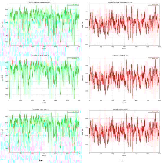
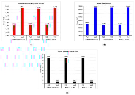
Figure 15.
OpenFAST coupled simulation results for generated power; (a) Time history under FLS; (b) Time his-tory under ULS, (c) Comparison of maximum displacement values; (d) Comparison of mean displacement values; (e) Comparison of displacement standard deviations for the UMaine VolturnUS-S, KSNU-1 15 MW, and KSNU-2 15 MW platforms.
The results show that all platforms produce nearly identical power output. Under normal operating conditions (FLS), the mean generated power is approximately 14.5 MW, and the differences between KSNU-1 15 MW, KSNU-2 15 MW, and the UMaine VolturnUS-S platform remain below 0.15%, which lies well within typical numerical uncertainty. The standard deviation of the generated power is also consistent across all configurations, indicating stable controller behavior and uniform distribution of aerodynamic and generator loads. Under extreme conditions (ULS), the mean power rises to about 15 MW, representing an increase of roughly 3% compared with FLS due to the higher wind speed and resulting thrust. The maximum power output for all platforms converges near 15 MW, further confirming that the structural modifications have no adverse impact on generator performance.
5. Conclusions
In this study, the reference wind turbine selected is the IEA-15-240-RWT developed by NREL. The work focuses on assessing the dynamic response of a 15 MW semi-submersible system equipped with different heave-plate configurations, with performance evaluated under both normal operating conditions (FLS) and extreme storm conditions (ULS) within a framework restricted to collinear wind and wave conditions and a limited set of IEC design load cases. The hydrodynamic loads are modelled using a potential flow approach complemented by additional viscous damping in the HydroDyn module of OpenFAST, which provides an approximate engineering representation of viscous effects. The baseline UMaine VolturnUS S platform is compared with two newly proposed variants, KSNU-1 15 MW and KSNU-2 15 MW, each incorporating a unique heave-plate design intended to enhance motion damping and hydrodynamic stability.
The results show that the KSNU platforms deliver measurable improvements in platform behavior while preserving power production. Translational motions remain nearly identical among the three platforms, with differences below 1% under both normal and extreme load conditions. KSNU-2 15 MW consistently exhibits the smallest surge, sway, and heave amplitudes, including reductions of 0.3% in surge and 0.6% in sway relative to the UMaine VolturnUS-S baseline, along with the lowest heave response and minimal vertical-motion variability.Rotational motions are modestly higher for KSNU-1 15 MW and KSNU-2 15 MW, increasing by about 5–8%, yet they remain well controlled and show no signs of instability. Yaw behavior shows no meaningful deviation, indicating that directional performance is governed mainly by the turbine controller. Peak responses follow the same pattern: translational extremes differ by less than 1%, while rotational extremes increase slightly but remain within acceptable limits.
Power production is essentially unchanged across all platforms, with mean values of 14.5 MW under normal conditions and convergence near 15 MW under extreme winds; differences between platforms stay below 0.15%. Overall, the integration of heave plates improves hydrodynamic damping, reduces motion variability, and maintains full energy capture, with the KSNU-2 configuration offering the most balanced and effective performance across the evaluated conditions.
Although the present study focuses on collinear wind and wave conditions and a limited set of design load cases to enable a first comparative assessment of the proposed heave plate configurations, several extensions are planned as part of ongoing and future work. Future studies will expand the set of IEC design load cases and extend the analysis to multi directional and misaligned sea states to provide a more robust assessment of platform performance. A more detailed mechanistic understanding of the observed changes in rotational motions will be sought through systematic sensitivity studies on heave plate geometry, hydrostatic properties, and the center of buoyancy, together with a refined treatment of viscous effects and vortex induced excitation. In addition, higher fidelity CFD simulations and targeted wave tank or field measurements are planned to supply further data for calibration and validation of the numerical model, thereby increasing the overall credibility of the results.
Author Contributions
Conceptualization, D.S. and J.O.; methodology, S.A.B. and D.S.; software, S.A.B. and H.C.; validation, S.A.B. and D.S.; formal analysis, S.A.B. and D.S.; investigation, S.A.B. and H.C.; resources, S.A.B., D.S. and J.O.; data curation, H.C. and J.N.; writing—original draft preparation, S.A.B., H.C., J.N. and J.O.; writing—review and editing, S.A.B., H.C. and D.S.; visualization, S.A.B.; supervision, D.S.; project administration, J.N. and D.S.; funding acquisition, J.N. and D.S. All authors have read and agreed to the published version of the manuscript.
Funding
This research was supported by Korea Institute of Energy Technology Evaluation and Planning (KETEP) grant funded by the Korea Government (MOTIE) of the Republic of Korea (20224000000040) and partly supported by Korea Institute of Energy Technology Evaluation and Planning (KETEP) grant funded by the Korea Government (MOTIE) of the Republic of Korea (20224000000220).
Data Availability Statement
The original contributions presented in the study are included in the article, further inquiries can be directed to the corresponding author/s.
Conflicts of Interest
The authors declare no conflicts of interest. The funders had no role in the design of the study; in the collection, analyses, or interpretation of data; in the writing of the manuscript; or in the decision to publish the results.
Abbreviations
| FOWT | Floating offshore wind turbine |
| LCOE | Levelized cost of energy |
| CFD | Computational fluid dynamics |
| DLC | Design load case |
| FLS | Fatigue limit state |
| ULS | Ultimate limit state |
| SWL | Still water line |
| M | Mass |
| A | Added mass |
| Brad | Radiation damping |
| Bvisc | Viscous damping |
| Chydro | Hydrostatic stiffness |
| Cmoor | Mooring restoring stiffness |
| Fext | Wave-induced external force |
| DOF | Degree of freedom |
| RAO | Response amplitude operator |
References
- Hong, S.; McMorland, J.; Zhang, H.; Collu, M.; Halse, K.H. Floating offshore wind farm installation, challenges and opportunities: A comprehensive survey. Ocean Eng. 2024, 304, 117793. [Google Scholar] [CrossRef]
- Liu, Y.; Xiao, Q.; Incecik, A.; Peyrard, C.; Wan, D. Establishing a fully coupled CFD analysis tool for floating offshore wind turbines. Renew. Energy 2017, 112, 280–301. [Google Scholar] [CrossRef]
- Rinker, J.; Gaertner, E.; Zahle, F.; Skrzypiński, W.; Abbas, N.; Bredmose, H.; Barter, G.; Dykes, K. Comparison of loads from HAWC2 and OpenFAST for the IEA Wind 15 MW Reference Wind Turbine. J. Phys. Conf. Ser. 2020, 1618, 052052. [Google Scholar] [CrossRef]
- Xu, S.; Xue, Y.; Zhao, W.; Wan, D. A review of high-fidelity computational fluid dynamics for floating offshore wind turbines. J. Mar. Sci. Eng. 2022, 10, 1357. [Google Scholar] [CrossRef]
- de Oliveira, M.; da Silva, L.S.P.; Puraca, R.; Carmo, B. CFD investigation of the IEA offshore 15 MW reference wind turbine performance in full scale: A temporal discretization analysis. In Proceedings of the ASME 42nd International Conference on Ocean, Offshore and Arctic Engineering (OMAE 2023), Melbourne, Australia, 11–16 June 2023. Paper No. OMAE2023-105084. [Google Scholar]
- Meng, H.; Liu, Y.; Tian, D.; Long, K.; Su, Y.; Li, B.; Sun, K. A novel conceptual design of a semi-submersible foundation for a 15 MW floating wind turbine. Ocean Eng. 2024, 294, 116726. [Google Scholar] [CrossRef]
- Bazher, S.A.; Park, J.; Oh, J.; Seo, D. Numerical investigation of wake characteristics for scaled 20 kW wind turbine models with various size factors. Energies 2024, 17, 4528. [Google Scholar] [CrossRef]
- Haider, R.; Li, X.; Shi, W.; Lin, Z.; Xiao, Q.; Zhao, H. Review of computational fluid dynamics in the design of floating offshore wind turbines. Energies 2024, 17, 4269. [Google Scholar] [CrossRef]
- Papi, F.; Bianchini, A. Technical challenges in floating offshore wind turbine upscaling: A critical analysis based on the NREL 5 MW and IEA 15 MW reference turbines. Renew. Sustain. Energy Rev. 2022, 162, 112489. [Google Scholar] [CrossRef]
- Mei, X.; Xiong, M. Effects of second-order hydrodynamics on the dynamic responses and fatigue damage of a 15 MW floating offshore wind turbine. J. Mar. Sci. Eng. 2021, 9, 1232. [Google Scholar] [CrossRef]
- Liang, L.; Liu, Y.; Yuan, Z.; Yan, G. Dynamic and structural performances of offshore floating wind turbines in turbulent wind flow. Ocean. Eng. 2019, 179, 92–103. [Google Scholar]
- Chen, M.; Jiang, J.; Zhang, W.; Li, C.B.; Zhou, H.; Jiang, Y.; Sun, X. Study on mooring design of 15 MW floating wind turbines in the South China Sea. J. Mar. Sci. Eng. 2024, 12, 33. [Google Scholar] [CrossRef]
- Eliassen, L.; Bachynski, E.E. The effect of turbulence model on the response of a large floating wind turbine. In Proceedings of the ASME 36th International Conference on Ocean, Offshore and Arctic Engineering (OMAE 2017), Trondheim, Norway, 25–30 June 2017. [Google Scholar]
- Lu, Z. CFD Analysis of Aerodynamic and Hydrodynamic Performance of the Floating Wind Turbine System Using Overset Grids. Master’s Thesis, Harbin Institute of Technology, Harbin, China, 2021. [Google Scholar]
- Pan, Q.; Mahfouz, M.Y.; Lemmer, F. Assessment of mooring configurations for the IEA 15 MW floating offshore wind turbine. J. Phys. Conf. Ser. 2021, 2018, 012030. [Google Scholar] [CrossRef]
- Medina-Manuel, A.; Botia-Vera, E.; Saettone, S.; Calderon-Sanchez, J.; Bulian, G.; Souto-Iglesias, A. Hydrodynamic coefficients from forced and decay heave motion tests of a scaled model of a floating wind turbine column equipped with a heave plate. Ocean Eng. 2022, 252, 110985. [Google Scholar] [CrossRef]
- Mello, P.C.; Malta, E.B.; da Silva, R.O.P.; Candido, M.H.O.; do Carmo, L.H.S.; Alberto, I.F.; Franzini, G.R.; Simos, A.N.; Suzuki, H.; Gonçalves, R.T. Influence of heave plates on the dynamics of a floating offshore wind turbine in waves. J. Mar. Sci. Technol. 2021, 26, 190–200. [Google Scholar] [CrossRef]
- Wang, H.; Yang, Y.; Guo, Y.; Lian, J. Influence of heave plate on the dynamic response of a 10 MW semisubmersible floating platform. J. Mar. Sci. Eng. 2024, 12, 2156. [Google Scholar] [CrossRef]
- Seo, D.-W.; Ahn, J.; Oh, J. Study on the shape of appendage for the reduction of motion of floating wind turbine platforms. J. Korean Soc. Mar. Environ. Saf. 2022, 28, 1201–1208. [Google Scholar] [CrossRef]
- Allen, C.; Viselli, A.; Dagher, H.; Goupee, A.; Gaertner, E.; Abbas, N.; Hall, M.; Barter, G. Definition of the UMaine VolturnUS-S Reference Platform Developed for the IEA Wind 15-Megawatt Offshore Reference Wind Turbine; NREL/TP-5000-76773; National Renewable Energy Laboratory: Golden, CO, USA, 2020. [Google Scholar]
- Liu, S.; Chuang, Z.; Wang, K.; Li, X.; Chang, X.; Hou, L. Structural parametric optimization of the VolturnUS-S semi-submersible foundation for a 15 MW floating offshore wind turbine. J. Mar. Sci. Eng. 2022, 10, 1181. [Google Scholar] [CrossRef]
- DNV GL. DNVGL-RP-C205: Environmental Conditions and Environmental Loads; Det Norske Veritas Germanischer Lloyd: Oslo, Norway, 2010. [Google Scholar]
- DNV GL. DNVGL-OS-E301: Position Mooring; Det Norske Veritas Germanischer Lloyd: Oslo, Norway, 2015. [Google Scholar]
- Niranjan, R.; Ramisetti, S.B. Insights from detailed numerical investigation of 15 MW offshore semi-submersible wind turbine using aero-hydro-servo-elastic code. Ocean Eng. 2022, 251, 111024. [Google Scholar] [CrossRef]
- Park, S.; Kim, K.-H.; Hong, K. Conceptual design of motion reduction device for floating wave-offshore wind hybrid power generation platform. J. Ocean Eng. Technol. 2018, 32, 9–20. [Google Scholar] [CrossRef]
- Otter, A.; Murphy, J.; Pakrashi, V.; Robertson, A.; Desmond, C. A review of modelling techniques for floating offshore wind turbines. Wind Energy 2022, 25, 831–857. [Google Scholar] [CrossRef]
- National Renewable Energy Laboratory (NREL). OpenFAST|Wind Research. Available online: https://www.nrel.gov/wind/nwtc/openfast (accessed on 6 October 2025).
- ANSYS Inc. Aqwa Theory Manual, Release 2025 R2; ANSYS Inc.: Canonsburg, PA, USA, 2025. [Google Scholar]
- OpenFAST Wave Stretching. HydroDyn User’s Guide and Theory Manual—OpenFAST Wave Stretching Documentation. Available online: https://openfast-wave-stretching.readthedocs.io/en/f-wave_stretching/source/user/hydrodyn/ (accessed on 2 December 2025).
- Jonkman, J.M.; Matha, D. Dynamics of offshore floating wind turbines—Analysis of three concepts. Wind Energy 2011, 14, 557–569. [Google Scholar] [CrossRef]
- Gao, Y.; Chen, Y.; Wang, L. Development of an aero-elastic-servo-hydro-mooring coupling framework for FOWT system. Appl. Ocean Res. 2025, 161, 104676. [Google Scholar] [CrossRef]
- International Electrotechnical Commission (IEC). IEC 61400-1: Wind Energy Generation Systems—Part 1: Design Requirements; IEC: Geneva, Switzerland, 2020. [Google Scholar]
- Stewart, G.M.; Robertson, A.; Jonkman, J.; Lackner, M.A. The creation of a comprehensive metocean data set for offshore wind turbine simulations. Wind Energy 2015, 18, 1151–1159. [Google Scholar] [CrossRef]
- Viselli, A.G.; Forristall, G.Z.; Pearce, B.R.; Dagher, H.J. Estimation of extreme wave and wind design parameters for offshore wind turbines in the Gulf of Maine using a POT method. Ocean Eng. 2015, 104, 649–658. [Google Scholar] [CrossRef]
Disclaimer/Publisher’s Note: The statements, opinions and data contained in all publications are solely those of the individual author(s) and contributor(s) and not of MDPI and/or the editor(s). MDPI and/or the editor(s) disclaim responsibility for any injury to people or property resulting from any ideas, methods, instructions or products referred to in the content. |
© 2025 by the authors. Licensee MDPI, Basel, Switzerland. This article is an open access article distributed under the terms and conditions of the Creative Commons Attribution (CC BY) license.